Guide to Virtual Private Networks via the Internet between WMO Information System Centres - WMO-No. 1116 - World Meteorological Organization
←
→
Page content transcription
If your browser does not render page correctly, please read the page content below
Guide to Virtual Private
Networks via the Internet
between WMO Information
System Centres

WMO-No. 1116
WMO-No. 1116

© World Meteorological Organization, 2016

The right of publication in print, electronic and any other form and in any language is reserved by WMO. Short extracts
from WMO publications may be reproduced without authorization, provided that the complete source is clearly
indicated. Editorial correspondence and requests to publish, reproduce or translate this publication in part or in whole
should be addressed to:

Chair, Publications Board
World Meteorological Organization (WMO)
7 bis, avenue de la Paix                                           Tel.: +41 (0) 22 730 84 03
P.O. Box 2300                                                      Fax: +41 (0) 22 730 80 40
CH-1211 Geneva 2, Switzerland                                      E-mail: publications@wmo.int

ISBN 978-92-63-11116-6

NOTE

The designations employed in WMO publications and the presentation of material in this publication do not imply the expression of
any opinion whatsoever on the part of the Secretariat of WMO concerning the legal status of any country, territory, city or area, or of
its authorities, or concerning the delimitation of its frontiers or boundaries.

Opinions expressed in WMO publications are those of the authors and do not necessarily reflect those of WMO. The mention of
specific companies or products does not imply that they are endorsed or recommended by WMO in preference to others of a similar
nature which are not mentioned or advertised.
WORLD METEOROLOGICAL ORGANIZATION
COMMISSION FOR BASIC SYSTEMS
OPAG ON INFORMATION SYSTEMS & SERVICES

Guide to Virtual Private Networks via the Internet between WMO
Information System Centres

CONTENTS
1       INTRODUCTION ..................................................................................................................................................... 6
2       WHAT IS A VIRTUAL PRIVATE NETWORK? ................................................................................................. 7
    2.1    DEFINITION ......................................................................................................................................................... 7
    2.2    TYPES OF VIRTUAL PRIVATE NETWORKS .......................................................................................................... 8
      2.2.1 Link-Layer solutions ................................................................................................................................... 8
            2.2.1.1         Asynchronous Transfer Mode and Frame Relay .................................................................................................... 8
            2.2.1.2         Multiprotocol Label Switching ............................................................................................................................... 9
            2.2.1.3         Virtual Private Local Area Network Service .......................................................................................................... 9
            2.2.1.4         Layer 2 Tunnelling Protocol and Point-to-Point Tunnelling Protocol ................................................................... 9
        2.2.2       Transport and application layers ............................................................................................................ 10
            2.2.2.1         Secure Socket Layer and Transport Layer Security ............................................................................................. 10
            2.2.2.2         Secure Shell .......................................................................................................................................................... 11
        2.2.3       So, why Internet Protocol Security? ...................................................................................................... 11
3       WHAT IS INTERNET PROTOCOL SECURITY? ............................................................................................ 12
    3.1         INTERNET PROTOCOL SECURITY ARCHITECTURE ........................................................................................... 12
    3.2         INTERNET PROTOCOL SECURITY SERVICES AND MODES ............................................................................... 13
    3.3         SECURITY ASSOCIATIONS ................................................................................................................................ 15
    3.4         AUTHENTICATION HEADERS ............................................................................................................................ 15
    3.5         ENCAPSULATING SECURITY PAYLOAD ............................................................................................................ 16
    3.6         INTERNET KEY EXCHANGE ............................................................................................................................... 16
    3.7         CONCLUSION .................................................................................................................................................... 17
4       INTERNET PROTOCOL SECURITY AND THE GLOBAL TELECOMMUNICATION SYSTEM ......... 18
    4.1    CRYPTOGRAPHY AND THE LAW ........................................................................................................................ 18
    4.2    QUICK VIEW OF THE GLOBAL TELECOMMUNICATION SYSTEM........................................................................ 18
      4.2.1 Physical layers .......................................................................................................................................... 18
      4.2.2 Upper layers .............................................................................................................................................. 19
    4.3    INTERNET .......................................................................................................................................................... 19
    4.4    SUGGESTED APPROACH................................................................................................................................... 19
    4.5    SOLUTION SUPPLIERS ...................................................................................................................................... 20
    4.6    NETWORK ARCHITECTURE ............................................................................................................................... 20
    4.7    IMPLEMENTATION SCENARIOS .......................................................................................................................... 21
    4.8    MULTICAST OVER INTERNET PROTOCOL SECURITY VIRTUAL PRIVATE NETWORKS ..................................... 21
    4.9    DYNAMIC MULTIPOINT VIRTUAL PRIVATE NETWORK SOLUTIONS................................................................... 22
    4.10 OPENVPN SOLUTIONS ..................................................................................................................................... 23
5       OPERATOR SOLUTIONS .................................................................................................................................... 26
    5.1         STAR, PARTIALLY MESHED AND FULLY MESHED NETWORKS ........................................................................... 26
    5.2         BRIEF INTRODUCTION TO MULTIPROTOCOL LABEL SWITCHING ..................................................................... 27
    5.3         INTERNET PROTOCOL SECURITY VIRTUAL PRIVATE NETWORKS OVER THE INTERNET ................................ 27
    5.4         CONCLUSION .................................................................................................................................................... 27
APPENDIX 1 EXAMPLE: CISCO-BASED CONFIGURATION ............................................................................. 30
APPENDIX 2 EXAMPLE: CISCO DYNAMIC MULTIPOINT VIRTUAL PRIVATE NETWORK
CONFIGURATION ......................................................................................................................................................... 39
APPENDIX 3 EXAMPLE: CONFIGURATION FOR AN OPENVPN-BASED SOLUTION ................................ 44
GLOSSARY AND IMPORTANT SECURITY-RELATED TERMS......................................................................... 51 BIBLIOGRAPHY ............................................................................................................................................................ 60
1 INTRODUCTION
After describing various concepts related to Virtual Private Networks (VPNs) and Internet Protocol Security
(IPSec), this publication presents a potential methodology for introducing a technical solution to the Global
Telecommunication System (GTS) component of the World Meteorological Organization (WMO) Information
System (WIS) and shows why these tools can enhance communication capabilities among WMO Members
for operational traffic exchanges. The title has been updated to highlight that the guidance is also applicable
for use on non-GTS links between WIS Centres as well as on the GTS.

Chapter 2 introduces the concept of a VPN and presents various technical alternatives to IPSec. As IPSec is
the most appropriate protocol for secure network-to-network communication, this publication will then focus
on this solution.

Chapter 3 briefly describes what IPSec is, because it is not a simple solution to understand. It covers many
technical aspects, allows various types of algorithms and is better described as a framework rather than a
protocol.

Chapter 4 focuses on the application of IPSec to GTS. A selection of protocols is proposed. It shows what
benefits WMO Members could expect from the use of IPSec.

Chapter 5 shows the technical evolution of Internet Protocol (IP) services from operators. Evolving from
Frame Relay, now deprecated, to IP solutions, operators offer VPN solutions that are either Multiprotocol
Label Switching (MPLS) based or IPSec based.

The appendices give complete configuration examples of routers from Cisco Systems, Inc., with the
protocols selected in chapter 3. These are followed by a glossary of terms related to VPNs and a
bibliography on IPSec.
2 WHAT IS A VIRTUAL PRIVATE NETWORK?

2.1 Definition

The definition below comes from What is a VPN? (Ferguson and Huston, 1998):

   Perhaps the simplest method of attempting to arrive at a simple definition for a VPN is to look at each word in the acronym
   individually, and then subsequently tie each of them together in a simple, common sense, and meaningful fashion.

   Let’s start by examining the word “network.” This is perhaps the least difficult term for us to define and understand, since the
   commonly accepted definition is fairly uncontroversial and generally accepted throughout the industry. A network consists of any
   number of devices which can communicate through some arbitrary method. Devices of this nature include computers, printers,
   routers, and so forth, and may reside in geographically diverse locations. The methods in which they may communicate are
   numerous, since there are countless electronic signalling specifications, and data-link, transport, and application layer protocols.
   For the purposes of simplicity, let’s just agree that a “network” is a collection of devices that can communicate in some fashion,
   and can successfully transmit and receive data amongst themselves.

   The term “private” is fairly straightforward, and is intricately related to the concept of “virtualization” insofar as a VPN is
   concerned, as we’ll discuss in a moment. In the simplest of definitions, “private” means that communications between two (or
   more) devices is, in some fashion, secret – that the devices which are not participating in the “private” nature of communications
   are not privy to the communicated content, and that they are indeed completely unaware of the private relationship altogether.
   Accordingly, data privacy and security (data integrity) are also important aspects of a VPN which need to be taken into
   consideration when considering any particular VPN implementation.

   Another means of expressing this definition of “private” is through its antonym, “public.” A “public” facility is one which is openly
   accessible, and is managed within the terms and constraints of a common public resource, often via a public administrative
   entity. By contrast, a “private” facility is one where access is restricted to a defined set of entities, and third parties cannot gain
   access. Typically, the private resource is managed by the entities that have exclusive right of access. Examples of this type of
   private network can be found in any organizational network which is not connected to the Internet, or to any other external
   organizational network, for that matter.

With this definition, the current GTS is a private network:

   These networks are private due to the fact that there is no external connectivity, and thus no external network communications.

   Another important aspect of “privacy” in a VPN is through its technical definition. For example, privacy in an addressing and
   routing system means that the addressing used within a VPN community of interest is separate and discrete from that of the
   underlying shared network, and from that of other VPN communities. The same holds true for the routing system used within the
   VPN and that of the underlying shared network. The routing and addressing scheme within a VPN should, in general, be self-
   contained, but this scenario degenerates into a philosophical discussion of the context of the term “VPN.” Also, it is worthwhile
   to examine the differences between the “peer” and “overlay” models of constructing VPNs—both of which are discussed in more
   detail later under the heading ”Network-Layer VPNs.”

   “Virtual” is a concept that is slightly more complicated. The New Hacker’s Dictionary (formerly known as the Jargon File) defines
   virtual as:

   virtual /adj./ [via the technical term “virtual memory,” prob. from the term “virtual image” in optics] 1. Common alternative
   to{logical}; often used to refer to the artificial objects (like addressable virtual memory larger than physical memory) simulated by
   a computer system as a convenient way to manage access to shared resources. 2. Simulated; performing the functions of
   something that isn’t really there. An imaginative child’s doll may be a virtual playmate. Oppose {real}.

   Insofar as VPN’s are concerned, the definition given in 2. above is perhaps the most appropriate comparison for virtual
   networks. The “virtualization” aspect is one that is similar to what we briefly described above as “private,” however, the scenario
   is slightly modified – the private communication is now conducted across a network infrastructure that is shared by more than a
   single organization. Thus, the private resource is actually constructed by using the foundation of a logical partitioning of some
   underlying common shared resource, rather than by using a foundation of discrete and dedicated physical circuits and
   communications services. Accordingly, the “private” network has no corresponding “private” physical communications system.
   Instead, the “private” network is a virtual creation which has no physical counterpart. The virtual communications between two
   (or more) devices are due to the fact that the devices which are not participating in the virtual communications are not privy to
   the content of the data, and that they are also altogether unaware of the private relationship between the virtual peers. The
   shared network infrastructure could, for example, be the global Internet and the number of organizations or other users not
   participating in the virtual network may literally number into the thousands, hundreds of thousands, or even millions.

   A VPN can also said to be a discrete network –
        discrete \dis*crete"\, a. [L. discretus, p. p. of discernere. See Discreet.] 1. Separate; distinct; disjunct.
The discrete nature of VPN’s allow both privacy and virtualization. While VPN’s are not completely separate, per se, the
distinction is that they operate in a discrete fashion across a shared infrastructure, providing exclusive communications
environments which do not share any points of interconnection. The combination of these terms produces VPN – a private
network, where the privacy is introduced by some method of virtualization. A VPN could be built between two end-systems or
between two organizations, between several end-systems within a single organization or between multiple organizations across
the global Internet, between individual applications, or any combination of the above.
The common and somewhat formal characterization of the VPN, and perhaps the most straightforward and strict definition, is:
A VPN is a communications environment in which access is controlled to permit peer connections
only within a defined community of interest, and is constructed through some form of partitioning
of a common underlying communications medium, where this underlying communications medium
provides services to the network on a non-exclusive basis.
This definition introduces a concept, VPNs, that is not related to any technical implementation.
There are many technical implementations of VPNs.
2.2 Types of Virtual Private Networks
A simplified version of the Transmission Control Protocol (TCP)/IP layer model is
shown in Figure 1.
The technical implementation of a VPN is related to this model:
(a) On the link layer, one can find:
(i) Asynchronous Transfer Mode (ATM) and Frame Relay
connection;
(ii) MPLS;
(iii) Virtual Private Local Area Network (LAN) service;
(iv) Link-Layer Encryption (Layer 2 Tunnelling Protocol (L2TP) or
Point-to-Point Tunnelling Protocol (PPTP));
(b) On the network layer:
(i) IPSec;
(c) On the transport and application layer:
(i) Secure Socket Layer (SSL) is a protocol proposed by Netscape
mainly for Hypertext Transfer Protocol (http) traffic encryption; the
successor of SSL is Transport Layer Security (TLS);
(ii) TLS is a proposed standard by the Internet Engineering Task
Force (IETF) based on SSL;
(iii) Secure Shell (SSH).
Figure 1. Simplified version of the TCP/IP layer model
2.2.1 Link-Layer solutions
2.2.1.1 Asynchronous Transfer Mode and Frame Relay
Following the definition of a VPN given above, early data networks, such as ATM and Frame Relay
solutions, must be considered as VPNs. In this case, VPNs rely on the operator.2.2.1.2 Multiprotocol Label Switching
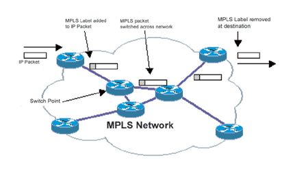
Nowadays, as IP is the base protocol, most of the provider solutions are based on MPLS, which is a protocol
originated by Cisco (the Tag Switching initiative), and which is now widely adopted.
In the traditional IP world, every router must route every packet on the network. Routing is rather complex
and slow. MPLS introduces (or uses) the concepts of tags. Packets are tagged at the entrance of the Wide
Area Network (WAN). Inside a WAN, packets are switched (not routed) based on the tag. Tags are removed
at the network exit.
This solution is now widely offered by operators.
2.2.1.3 Virtual Private Local Area Network Service
The Virtual Private LAN Service is a way of providing Ethernet-based multipoint-to-multipoint communication
over IP or MPLS networks. It allows geographically dispersed sites to share an Ethernet broadcast domain
by connecting sites through pseudo-wires, and the Virtual Private LAN allows any-to-any (multipoint)
connectivity.
2.2.1.4 Layer 2 Tunnelling Protocol and Point-to-Point Tunnelling Protocol
Two solutions that are mainly dedicated to remote access are L2TP and PPTP. In a normal situation, a
remote user who wants to connect to the Intranet uses a Point-to-Point Protocol (PPP) connection to a
remote-access server. In this case, the username and password (and also data) are transferred in plain text
and therefore might be sniffed by potential intruders. The encryption of traffic between peers is permitted by
L2TP and PPTP, leading to better security.
2.2.1.4.1 Point-to-Point Tunnelling Protocol
PPTP is a layer 2 protocol that encapsulates PPP frames in IP datagrams for transmission over an IP
internetwork, such as the Internet. PPTP can be used for remote-access and router-to-router VPN
connections. PPTP is documented in Request for Comments (RFC) 2637 (RFCs are available at
www.ietf.org/rfc.html).
PPTP uses a TCP connection for tunnel maintenance and a modified version of Generic Routing
Encapsulation (GRE) to encapsulate PPP frames for tunnelled data. The payloads of the encapsulated PPP
frames can be encrypted and/or compressed. Figure 2 shows the structure of a PPTP packet containing user
data.
Figure 2. Structure of a PPTP packet
2.2.1.4.2 Layer 2 Tunnelling Protocol
L2TP is a combination of PPTP and Layer 2 Forwarding (L2F), a technology proposed by Cisco. L2TP
represents the best features of PPTP and L2F, and encapsulates PPP frames to be sent over IP, X.25,
Frame Relay or ATM networks. When configured to use IP as its datagram transport, L2TP can be used as a
tunnelling protocol over the Internet. L2TP is documented in RFC 2661.Over IP networks, L2TP uses User Datagram Protocol (UDP) and a series of L2TP messages for tunnel
maintenance. It also uses UDP to send L2TP-encapsulated PPP frames as tunnelled data (see Figure 3).
The payloads of encapsulated PPP frames can be encrypted and/or compressed.
Figure 3. Structure of IP packet containing L2TP encapsulated PPP frame using UDP
In Windows operating system versions, starting from Windows 2000, IPSec Encapsulating Security Payload
(ESP) is used to encrypt the L2TP packet. This is known as L2TP/IPSec. The result after applying ESP is
shown in Figure 4.
Figure 4. IP packet containing information encrypted using L2TP/IPSec
2.2.2 Transport and application layers
Transport and application layers mainly cover host-based solutions.
2.2.2.1 Secure Socket Layer and Transport Layer Security
Netscape created the protocol SSL. In the TCP/IP layering model, it is on top of the TCP layer. Therefore, it
could be used for adding security (strong authentication and encryption) for all TCP-based applications
(telnet, File Transfer Protocol (FTP), etc.). SSL is no longer recommended for use, and all SSL versions
have deprecated by now. The recommended protocol is now TLS. Companies use this technology to provide
secure remote access to their internal infrastructure by using SSL/TLS VPNs with additional strong
authentication, often using either one-time password generators or X.509 certificates. The advantage is that
no VPN client software has to be installed on the client computers in advance. Instead, the VPN client
software is downloaded as ActiveX controls or Java applets just before the VPN connection is established.In addition to commercial SSL VPN solutions, there are also powerful public-domain VPN solutions such as
OpenVPN (Open Source VPN) and stunnel, which can be used free of charge.
Other implementations exist for these protocols, but the success story of SSL is Hypertext Transfer Protocol
Secure (HTTPS). It is used in e-commerce applications to allow secure information exchanges between
clients and servers. TLS is the IETF proposed standard and the successor of SSL and is also an IETF
standard.
2.2.2.2 Secure Shell
SSH is another application layer authentication and encryption protocol. SSH frequently asked questions
give the following definition of SSH:
Secure Shell is a program to log into another computer over a network, to execute commands in a remote machine, and to
move files from one machine to another. It provides strong authentication and secure communications over insecure channels.
It is intended as a replacement for telnet, rlogin, rsh and rdist.
For SSH2, there also is a replacement for FTP: sftp.
Therefore, the main use of SSH is within organizations. In theory, to manage security-based devices
(firewalls, etc.), or to gain root access on hosts, the network/system administrator should avoid connecting
remotely using telnet to the box. If telnet is used, it is very easy, with a sniffer, to capture and analyse the
packets to gain administrative access on the firewall/system. With direct access, no clear user/password will
be exchanged on LAN. However, network administrators are often lazy; SSH is the answer in this case!
Among other things, SSH includes an encrypted replacement tool for telnet.
SSH is becoming very popular for secure remote management and also for secure remote data transfer.
2.2.3 So, why Internet Protocol Security?
The Manual on the Global Telecommunication System (WMO-No. 386) presents two solutions to exchange
traffic between Message Switching Systems (MSS) using the IP protocol. One is based on FTP and the
other on sockets.
This manual does not cover the WAN infrastructure. The current GTS is a mix of leased lines, peer-to-peer
Frame Relay links, global Frame Relay services and MPLS networks (such as the Regional Meteorological
Data Communications Network (RMDCN) in WMO Region VI). For economic reasons, and with regards to
the overall high quality of the Internet service, it might be a good opportunity to study the potential use of the
Internet to complement GTS.
However, although it is reliable (but has no real Service Level Agreement (SLA)), the Internet is, by nature,
an insecure network. Documents within WMO (for example, WMO-No. 1115) show how National
Meteorological Centres (NMCs) should connect to the Internet (firewalls, etc.).
In order to allow a smooth introduction of the Internet to complement GTS, the following rules should apply:
– Permit the use of the current protocols (FTP and socket) on the Internet;
– Avoid any impact on MSS;
– Guarantee an acceptable level of trust for members.
The first two points mean that the proposed solution should be transparent to the application and the hosts.
Among the protocols described above, IPSec is the only one that is completely application independent.
To offer a minimum level of trust, authentication (who wants to talk to me) and encryption (no one except me
can understand the data) are both needed. IPSec offers these two services.3 WHAT IS INTERNET PROTOCOL SECURITY?
3.1 Internet Protocol Security architecture
From RFC 2401 (now replaced by RFC 4301; RFC 4301, partly replaced by RFC 6040; and RFC 7619):
IPSec is designed to provide interoperable high quality, cryptographically-based security for IPv4
and IPv6. The set of security services offered includes access control, connectionless integrity, data
origin authentication, protection against replays, confidentiality, and limited traffic flow
confidentiality. These services are provided at the IP layer offering protection for the IP and upper
layer protocols.
Specification of IPSec is rather complex. The overall architecture of the specification can be seen as a suite
of interacting protocols. The organization of the specifications is given in RFC 4301 (Figure 5):
Architecture
RFC 4301
ESP Protocol AH Protocol
RFC 4303 RFC 4302
Encryption Authentication
Algorithm Algorithm
DOI
Policy
RFC 5282
Key
Management
Figure 5. IPSec document overview
(a) Architecture covering the general concepts, security requirements, definitions and mechanisms defining
IPSec technology:
(i) Defines the capabilities that hosts and routers should provide;
(ii) For example, it is required that the hosts provide confidentiality using ESP, however, RFC 4301
does not specify the header format;
(iii) Describes the interaction between IPSec and the rest of TCP/IP;
(b) ESP and Authentication Header (AH):
(i) Define the protocol, the payload header format and the services they provide;
(ii) Define the packet processing rules;
(iii) Do not specify the cryptographic transforms that are used to provide these capabilities; this allows
the transforms to be changed if they become cryptographically insecure, without any change in the
base protocol;
(c) Encryption algorithm and authentication algorithm:(i) A set of documents that describes how various encryption algorithms are used in ESP or how
various authentication algorithms are used in AH and the authentication part of ESP;
(ii) Define the algorithm, the key sizes, the derivation of keys, transformation processes and any
algorithm-specific information;
(iii) The definitions have to be very specific in order to obtain interoperability;
(d) Key management describing the key management schemes:
(i) Keys are generated with Internet Key Exchange (IKE) in IPSec protocols;
(ii) The payload format of IKE is very generic, it can be used to negotiate keys in any protocol, and IKE
is also used for negotiating keys for other protocols outside IPSec;
(iii) Genericity is achieved by separating the parameters IKE negotiates from the protocol itself;
(e) Domain of Interpretation (DOI) contains values required for the other documents to relate to each other,
that is, identifiers for approved encryption and authentication algorithms, and operational parameters
such as key lifetime:
(i) The parameters negotiated by IKE are defined in DOI;
(f) Policy is an important component:
(i) It determines if two entities will be able to communicate with each other, and if so, which transforms
to use;
(ii) Policy representation deals with definition, storage and retrieval of policy;
(iii) Policy implementation addresses the application of policy for actual communication involving, for
example, the application of negotiated keys in the communication.
All the above documents are RFCs, and, as often occurs with RFCs, they can be difficult to understand!!
The following paragraphs introduce IPSec and some of its key points.
3.2 Internet Protocol Security services and modes
The IPSec framework has been built and defined in such a way to guarantee maximum independence
between different parts of the system (for example, the encryption algorithm and the authentication algorithm
are not linked to ESP and AH protocols). The goal of IPSec is to offer security through encryption, and it was
decided to split the solution into several parts. This led to a very powerful solution, and depending on the
goal one wants to reach, the good protocols may be chosen from among a large choice. However, it may
lead to some incompatibility.
It must also be noted that in the first design (the first set of RFCs was published in 1995), the ESP protocol
was not usable for authentication. In the second set (published in late 1998), the ESP protocol also offered
authentication solutions. The third set of RFCs related to IPSec, in 2005, confirmed this architecture.
When two systems want to exchange data using IPSec, they must first determine the services they want to
use from IPSec. The table below summarizes the services offered by ESP and AH.
IPSec services
ESP (encryption and
AH ESP (encryption only)
authentication)
Access control ➼ ➼ ➼
Connectionless integrity ➼ ➼
Data origin authentication ➼ ➼
Rejection of replayed
➼ ➼ ➼
packets
Confidentiality ➼ ➼
Limited traffic flow
➼ ➼
confidentialityThis is the first step, but not the last!
The next step is to decide if tunnel mode or transport mode should be used. Transport mode is mainly
designed for host-to-host communication where IPSec is embedded in the host operating system. In tunnel
mode, the hosts are not in charge of IPSec, and some boxes between the hosts carry out this job.
Figures 6 and 7 show the structures of the packets in the two modes.
Application Data Data created from upper layer
TCP Transport information is applied
Transport Data
Header for end-to end communication
IP TCP Network information is applied
Data
Header Header (Normal Network Layer Information)
IP TCP IPSec isolates IP Header
Data
Header Header from upper layer data
IP TCP
Network Data IPSec encrypts upper layer data
Header Header
IP ESP/ TCP ESP IPSec applies the security protocol
Data
Header AH Header TRL
IP ESP/ TCP ESP
Data The packet is reassembled
Header AH Header TRL
Figure 6. IPSec operations within transport mode
In transport mode, the real IP header of the packet is used along the way, and the IP addresses of the hosts
are used to route the packet. This means that if the packet is going on the Internet, IP addresses of both
hosts must be routable.Application Data Data created from upper layer
TCP Transport information is applied
Transport Data
Header for end-to end communication
IP TCP Network information is applied
Data
Header Header (Normal Network Layer Information)
IP TCP
Data IPSec encrypts datagram
Header Header
Network ESP/ IP TCP ESP IPSec applies the security
Data
AH Header Header TRL protocol
IP ESP/ IP TCP ESP IPSec build new
Data IP header
Header AH Header Header TRL
IP ESP/ IP TCP ESP
Data The packet is reassembled
Header AH Header Header TRL
Figure 7. IPSec operations within tunnel mode
In tunnel mode, the real IP addresses are embedded in the new IPSec packet. If the packet is routed over
the Internet, the new IP addresses must be routable.
3.3 Security Associations
Security Associations (SAs) in IPSec terminology form the basis for IPSec operations. SAs are contracts
between two entities determining the IPSec protocols used for securing the packets, the transforms, the keys
and their duration, plus many other things.
Before two entities are able to exchange packets using IPSec, they must first create SAs, which are always
one way (simplex). Therefore, if hosts A and B are communicating with IPSec, each host will have two SAs:
SAin and SAout. Parameters SAin for host A and SAout for host B will share the same cryptographic parameters.
Likewise, SAs are protocol specific. There is an SA for each protocol: ESP and AH. Each IPSec host
therefore has to keep a database (the Security Association Database (SADB)) to store all SAs; the Security
Parameter Index is a 32 bit element used to identify SA in SADB. SAs are managed (created and deleted)
either manually or with a protocol, and in this case, the protocol used is IKE. It is outside of the scope of this
publication to describe the exact and complete use of SAs, but it must be clear that SAs are the basis of the
IPSec framework.
In the framework presented above, SA is linked to policy and DOI. SAs are the links between concepts
(IPSec framework) and reality (how to really use all these things in data communication).
3.4 Authentication Headers
AHs provide data security and authentication of IP packets:
– Data integrity ensures that undetected modification to a packet content in transit is not possible;– Authentication features enable end systems or network devices to authenticate the user or the
application and filter traffic accordingly;
– Prevent address spoofing attacks;
– Protect against replay attacks.
The first three functions are guaranteed by an authentication hash function. A Message Authentication Code
function is an authentication process combined with a symmetrical key. To make it short, these functions
calculate a digest of the message, and then the digest is encrypted with a shared secret between the two
hosts.
A digest is the result of a fixed-length mathematical calculation. It has been proven that it is very unlikely to
recreate the digest if the original information was altered, as it would be too time-consuming.
Such techniques are used, for example, on public FTP servers. When publishing a file on a server, it is
useful to also put the digest of the file on the same server. The digest guarantees that the original file has not
been modified by anyone.
The most well-known digest calculation method is MD5. However, as it is also an insecure method, the use
of Secure Hash Algorithm (SHA)-256 is now recommended.
The required protocol for AH is Hashed Message Authentication Code (HMAC)-SHA-1, but HMAC-SHA-256
is recommended.
The last function in AH (anti-replay attack) is built with a mechanism of a sliding window. Each packet
receives a sequence number, and various techniques guarantee that the packet cannot be replayed without
notice.
3.5 Encapsulating Security Payload
ESP offers two services:
– Encryption: the data are encrypted with a predefined protocol between the two hosts;
– Authentication: see AH.
In the first release of RFCs regarding IPSec, AH was used for authentication and ESP for encryption only. It
has been shown by further study that encryption without authentication was not secure. As the old RFCs
allowed the use of ESP without AH, it was decided to add the capability to authenticate within ESP to the
new RFCs.
There is now some redundancy. It is possible to use AH to authenticate, and to use ESP to also authenticate
and encrypt. Bruce Schneier, a well-known cryptographic specialist, suggests using ESP for both, and to
forget about AH.
The authentication algorithms usable in ESP are:
– Triple Data Encryption Standard (3DES) in Cipher Block Chaining mode (this is a mandatory
protocol);
– Advanced Encryption Standard (AES) in Cipher Block Chaining mode;
– AES counter mode.
DES has been deprecated in the latest version of the protocol, and therefore must not be used.
AES is now the de facto standard and should be used for encryption.
3.6 Internet Key ExchangeIn order to talk to each other, peers must use SAs, which define the security parameters and authentication
keys to use. IKE is the protocol used to create and exchange SAs.
However, nothing is simple in IPSec theory. In fact, IKE covers three different protocols:
– Internet Security Association and Key Management protocol (ISAKMP);
– Oakley Key Determination Protocol;
– SKEME Versatile Secure Key Exchange Mechanism.
ISAKMP defines the language for negotiation. It defines the payload format, the mechanics of implementing
a key exchange and the negotiation of an SA. It does not define the key exchange algorithm, but rather the
message types in order to exchange keys.
Oakley and SKEME are two key exchange protocols usable under the ISAKMP umbrella in the IKE world.
In fact, ISAKMP, Oakley and SKEME were already developed protocols and IKE is the binding element
between all of these.
3.7 Conclusion
In this brief introduction to IPSec, it has been shown that:
– Two modes exist: tunnel and transport;
– Two protocols that are partially redundant are defined: ESP and AH;
– SAs are created and maintained by three different protocols;
– Authentication can be achieved through two possible algorithms;
– Encryption relies on 3DES or AES.
Other aspects that may also be relevant in IPSec have not been covered, but include:
– Diffie–Helmann protocol to exchange keys;
– X.509v3 certificates;
– Public Key Infrastructure (PKI).
In some aspects, VPN is a vague concept; IPSec, one of the VPN solutions, is not much clearer!
Therefore, despite the rather ugly face of the protocol, the various options and the risk of incompatibility,
IPSec is now widely implemented and available on many platforms, including, routers, dedicated boxes,
firewalls, hosts, etc.
In fact, in most cases, the solutions implemented only cover part of the possible options. It is therefore very
important to guarantee interoperability to share the same subset among peers.
In the following chapter, a possible scenario is suggested, taking into account the need for security, some
legal aspects and some interoperability issues.4 INTERNET PROTOCOL SECURITY AND THE
GLOBAL TELECOMMUNICATION SYSTEM
4.1 Cryptography and the law
In VPN and IPSec, cryptography is one of the key aspects for ensuring privacy of communication.
Governments in all countries still consider cryptography as some sort of weapon. It has often been explained
by different governments in the world that lawful activities perhaps need privacy, but the main use of
cryptography tools was for unlawful activities. Therefore, every country has defined rules about the use of
cryptography within the country.
Wikipedia describes the situation regarding cryptography in many countries
(https://en.wikipedia.org/wiki/Wassenaar_Arrangement):
The Wassenaar Arrangement on Export Controls for Conventional Arms and Dual-Use Goods and Technologies, commonly
known as the Wassenaar Arrangement, is a multilateral export control regime (MECR) with 41 participating states including
many former COMECON (Warsaw Pact) countries.
The Wassenaar Arrangement was established to contribute to regional and international security and stability by promoting
transparency and greater responsibility in transfers of conventional arms and dual-use goods and technologies, thus preventing
destabilizing accumulations. Participating States seek, through their national policies, to ensure that transfers of these items do
not contribute to the development or enhancement of military capabilities which undermine these goals, and are not diverted to
support such capabilities.
It is the successor to the Cold War-era Coordinating Committee for Multilateral Export Controls (COCOM), and was established
on 12 July 1996, in Wassenaar, the Netherlands, which is near The Hague. The Wassenaar Arrangement is considerably less
strict than COCOM, focusing primarily on the transparency of national export control regimes and not granting veto power to
individual members over organizational decisions. A Secretariat for administering the agreement is located in Vienna, Austria.
Like COCOM, however, it is not a treaty, and therefore is not legally binding.
Import or use of cryptographic solutions is controlled in a large number of countries.
Before any use of cryptographic solution, everyone and especially government
agencies such as National Meteorological Centres MUST verify if the solution they
want to use is legal in their country.
4.2 Quick view of the Global Telecommunication System
4.2.1 Physical layers
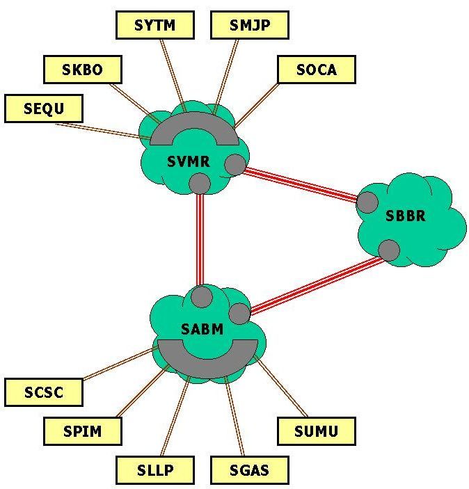
The current GTS is a mix of various technical solutions:
– Leased line;
– Frame Relay lines, where the leased line is replaced by a connection to a Frame Relay network,
but only two peers share the same Frame Relay network;
– An MPLS network such as RMDCN (as the WIS core network) is such a network;
– Connections using the Internet;
– Satellite communication channels.
The disadvantages of the first three solutions are similar:
– For (relatively) slow-speed lines, the price is high;– Both the leased line and the Private Virtual Channel (PVCs) in Frame Relay are point-to-point
links and therefore work well for point-to-point communication, but not for many-to-many nor
any-to-any communication.
MPLS with the any-to-any feature improves the situation, but the cost may still be an issue in some cases.
However, the current requirements in telecommunications become increasingly higher in terms of:
– Traffic;
– Global exchange.
With the growth of products and data, and with the WIS network, National Centres, Data Collection or
Production Centres and Global Information System Centres will want to exchange much more information.
The architecture based on the concentration through a hub site and costly slow-speed links is not suitable for
these new challenges.
4.2.2 Upper layers
At the application layer, for GTS data exchange, two protocols are usable on top of the IP layer: FTP and
sockets. Every new solution must be compatible with these standards.
4.3 Internet
Most GTS sites are now connected to the Internet. The Internet connection is in most cases:
– Usually reliable: The Internet Service Providers (ISPs) deliver the connections to the Internet.
They are operated just like other connecting lines and are therefore as reliable as the lines.
However, it must be noted that no end-to-end SLAs could be defined on the Internet.
– Powerful: The Internet connection is often a high-speed connection.
– Secure: The sites must be protected by security systems such as security gateways (firewalls),
malware filters, etc.
Therefore, the Internet is now a possible media to complement the current GTS private infrastructure, and it
is already used as the connection to GTS in many countries.
4.4 Suggested approach
As seen previously, the only real application and host-independent VPN solution is IPSec.
Therefore, for WMO use, IPSec is recommended as the VPN solution.
However, in order to guarantee interoperability between NMCs without redefining the protocols to use each
time, the following implementation solution is suggested:
– Tunnel mode: As IPSec will mostly be configured on routers, firewalls or dedicated boxes, and
taking into account that neither encryption nor authentication are mandatory on LAN, tunnel
mode is the most appropriate solution;
– AH should not be used, ESP should be used for authentication, and authentication should be
carried out with HMAC-SHA-256;
– Pre-shared secrets: Using the X.509v3 certificate is probably a more elegant solution, but in
practice, it is more difficult to implement in WMO situations.
If necessary, encryption using AES-256 should be used.
These recommendations mostly come from A Cryptographic Evaluation of IPsec (Ferguson and Schneier,
2003).4.5 Solution suppliers
With the subset of protocols defined above, each GTS site can choose any supplier for VPN equipment.
In addition to commercial products, there is also a wide range of open-source software offering IPSec-based
VPN functionality.
All IPSec implementations should be compatible. However, as seen previously, IPSec offers a large choice
of configuration parameters. The solution proposed in section 4.4 is included in the mandatory subset of
protocols described in RFCs. Therefore, any RFC-compliant solution should interoperate with any other.
However, in some cases, different IPSec end points do not interoperate. Before choosing a VPN box, sites
should check with their potential VPN neighbours if their respective solutions are compatible.
Over the last seven years, the European Centre for Medium-Range Weather Forecasts (ECMWF) and its
partners in Europe made many tests on IPSec. In 2007, ECMWF showed that interoperability is still an issue.
The tests involving Cisco, Nortel (with Checkpoint software) and Nokia (also with Checkpoint) were
successful. However, the hassle to configure multiple different devices convinced ECMWF and its partners
to agree on a common platform before large-scale implementation.
4.6 Network architecture
The placement of the VPN gateway in a security solution is of paramount importance. Improper placement of
the VPN gateway will affect the effectiveness of the solution. In this context, all the VPN gateways operate in
tunnel mode only. The following few scenarios of VPN gateway placement highlight this point. Emphasis is
placed on the Intranet infrastructure and the demilitarization zone (DMZ), which is typically meant for limited
authorized access. Servers that are put into DMZ include web servers and external mail servers.
Several different solutions are available, and two solutions are highlighted in the following:
– The simplest one is a firewall and a VPN gateway within the same box;
– The second one is a VPN gateway adjacent to the firewall.
It should be noted that this architecture must be coherent with the security policy of the site.
Figure 8. VPN gateway is implemented on the firewall
In Figure 8, a VPN gateway function is implemented on a firewall and the firewall connects to the Internet.
The flow of traffic is from the Internet to the firewall/VPN gateway directly. This will be a more cost-effective
solution as there is no need for a separate VPN gateway. Placing both the function firewall and VPN onto the
same box results in easier management. Note that this set-up is typically used for smaller VPN solutions.
The disadvantage of this solution is that the Central Processing Unit (CPU) utilization of the firewall/VPN
gateway will be very high, and adequate measures have to be taken to address this issue. In other words,this set-up introduces additional software components in the firewall and hence results in further
performance degradation. Another disadvantage of this solution is that it requires more services/ports to be
opened. As a result, the security implementation may suffer from additional security holes. In addition, the
more services that are running on a single (security) system, the higher the risk of being hacked. Finally, the
firewall poses a single point of failure for the VPN solution.
Figure 9. VPN gateway in a dedicated DMZ
In Figure 9, the VPN gateway is connected to a (dedicated) interface of the Internet firewall. The flow of
traffic into the Intranet will be through the firewall. However, the Internet traffic will arrive either:
– From the Internet via the firewall; or
– From the Internet directly to the external interface of the VPN gateway and then to the firewall.
The advantage of this set-up is that both types of clients (VPN and non-VPN) can be supported. All the
clients will be subject to the firewall policy.
The most advanced scenario introduces another firewall dedicated to control VPN traffic. From one box for
all the dedicated boxes, there are many different options, from the cheapest to the most expensive.
However, as a general statement, the best solution for one site is the solution that conforms with the security
policy and where the advantages and the disadvantages of the solutions are well understood.
4.7 Implementation scenarios
In order for two GTS sites to establish a VPN link, they must:
(a) Agree upon the protocols to be used (mode, authentication and/or encryption, Message Digest
Algorithm, site authentication);
(b) Define the pre-shared secret – this password must be defined and must be the same on both
sides;
(c) Confirm the VPN platforms to be used;
(d) Agree on IP addresses for the exchange of data over the link;
(e) Set up appropriate filter rules on the firewall, with the following rules:
(i) Allow UDP port 500 to be used for ISAKMP;
(ii) Allow UDP port 4500 (Network Address Translation (NAT) traversal);
(iii) Allow IP protocol number 50 (ESP protocol);
These are the basic rules for an IPSec connection;
(f) Implement the defined configuration;
(g) Test.
Once everything is running, the main risk is the potential failure of the virtual link created.
4.8 Multicast over Internet Protocol Security Virtual Private NetworksFor communication in future WIS systems, it could be an advantage to exchange certain sets of data using
multicast instead of unicast communication.
As the IPSec protocol is a PPP, and does not have point-to-multipoint capabilities by definition, sending
multicast traffic over an IPSec VPN with more than two sites will require the use of additional tunnels (GRE
or IP-in-IP) today.
An example of such a solution is the Dynamic Multipoint Virtual Private Network (DMVPN) solution from
Cisco, which is briefly described below.
4.9 Dynamic Multipoint Virtual Private Network solutions
A DMVPN is a proprietary Cisco Internetworking Operating System (IOS) solution for building IPSec and
GRE VPNs in a scalable way. It relies on two Cisco technologies: Next Hop Resolution Protocol (NHRP) and
multipoint GRE tunnel interfaces. A DMVPN does not alter the standards-based IPSec VPN tunnels, but it
does change their configuration.
A spoke router registers its real public IP interface address when it boots and a hub maintains an NHRP
database of all the spoke’s real public interface addresses. Subsequently, spoke routers query the NHRP
database for real addresses of destination spoke routers to dynamically build direct tunnels. The multipoint
GRE tunnel interface allows single GRE interfaces to support multiple IPSec tunnels.
In a typical hub-and-spoke IPSec design, all VPN traffic travels via the hub site, which acts as a gateway.
Therefore, the hub bandwidth and the CPU utilization limit the VPN size. In the DMVPN dynamic-mesh
approach, spoke-to-spoke tunnels can be dynamically built when required. This means that spoke routers
only need to support tunnels currently in use, and hub routers only support spoke–hub traffic and overflow
from spoke-to-spoke traffic.
In the context of GTS, a DMVPN-based infrastructure was deployed as a backup for RMDCN in a large-
scale operational pilot at the beginning of February 2010 for the following reasons:
– The RMDCN Customer Edge (CE) router is a Cisco router running IOS;
– The traffic re-routing between the RMDCN and the DMVPN infrastructures can be carried out in
a fast, automatic and reliable manner.
The following constraints apply to the DMVPN-based infrastructure:
– The solution maintains the RMDCN any-to-any connectivity;
– The use of dedicated Cisco routers;
– The use of a subset of Cisco routers running specific IOS versions in order to limit
troubleshooting and maintenance issues;
– The DMVPN equipment is locally managed;
– The use of DMVPN is an additional option to the portfolio of the available RMDCN backup
mechanisms (mission critical and Integrated Services Digital Network (ISDN)).
The DMVPN topology selected is “single DMVPN/dual hub”, and the spoke site deployed by the DMVPN
router is in accordance with the following technical requirements:
– The Cisco DMVPN router has to be installed on the same physical LAN/DMZ segment as the
RMDCN CE router;
– The DMVPN router needs to have a public IP address reachable through the Internet – no NAT
should be deployed;
– The DMVPN router must be able to establish IPSec tunnels to other DMVPN RMDCN sites and
send encrypted RMDCN traffic through them, to allow the IPSec protocols to and from the
DMVPN router’s public IP address, that is, ESP, GRE, IKE (UDP 500) and NAT-T (UDP 4500)
protocols.4.10 OpenVPN solutions
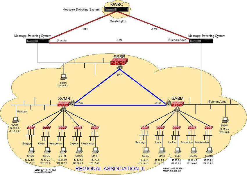
To provide a connectivity environment to allow all 13 NMCs in WMO Region III to be connected to each
other using a VPN over the Internet, a VPN solution based on freely available software (OpenVPN) and
the operating system Linux was set up.
OpenVPN is a full-featured open-source SSL VPN solution that accommodates a wide range of
configurations, including remote access, site-to-site VPNs, Wi-Fi security, and enterprise-scale remote-
access solutions with load balancing, failover and fine-grained access controls. Starting with the
fundamental premise that complexity is the enemy of security, OpenVPN offers a cost-effective,
lightweight alternative to other VPN technologies.
The lightweight design of OpenVPN sheds many of the complexities that characterize other VPN
implementations. The OpenVPN security model is based on SSL, the industry standard for secure
communications via the Internet. OpenVPN implements Open Systems Interconnection layer 2 or 3
secure network extensions using the SSL/TLS protocol, supports flexible client authentication methods
based on certificates, smart cards and/or two-factor authentication, and allows user- or group-specific
access control policies using firewall rules applied to the VPN virtual interface. OpenVPN is not a web
application proxy and does not operate through a web browser.
It was decided to create three networks using the OpenVPN software to facilitate the configuration and let
the operation be more flexible:
– One core network connection between the three Regional Telecommunication Hubs (RTHs);
– One network covering the north part of the region;
– One network covering the south part of the region.
This set-up is shown in Figure 10.Figure 10. VPN map for WMO Region III using GTS headers names RTH Buenos Aires will provide a server to collect the data from their neighbouring centres. RTH Maracay will provide the same approach to get data from the centres concerned to areas of responsibility. The RTHs will have a special configuration in order to provide bidirectional communication between the centres involved. The network connection of the three RTHs in the region will be called the core network. It will be the access point for GTS though the message switching system. Each RTH will host the servers for the VPN connections. The south part of Region III, comprising NMCs for Colombia, Ecuador, Suriname, Guyana and French Guyana, will preferentially be a client for the server hosted by Maracay. In case of emergency or backup, they can connect to RTH Brasilia or RTH Buenos Aires. The north part of Region III, comprising NMCs for Chile, Peru, Plurinational State of Bolivia, Paraguay and Uruguay, will preferentially be a client for the server hosted by Buenos Aires. In case of emergency or backup, they can connect to RTH Brasilia or RTH Maracay. In all cases, the servers will provide a fixed and private IP address for the logical tunnel between NMCs and RTHs in order to facilitate and guarantee the communication. Figure 11 illustrates the designed set-up.
You can also read