Experiences with Modeling Network Topologies at Multiple Levels of Abstraction - Usenix
←
→
Page content transcription
If your browser does not render page correctly, please read the page content below

Experiences with Modeling Network
 Topologies at Multiple Levels of Abstraction
Jeffrey C. Mogul, Drago Goricanec, Martin Pool, Anees Shaikh, Douglas Turk, and
            Bikash Koley, Google LLC; Xiaoxue Zhao, Alibaba Group Inc.
             https://www.usenix.org/conference/nsdi20/presentation/mogul

        This paper is included in the Proceedings of the
    17th USENIX Symposium on Networked Systems Design
                and Implementation (NSDI ’20)
                  February 25–27, 2020 • Santa Clara, CA, USA
                                  978-1-939133-13-7

                                         Open access to the Proceedings of the
                                        17th USENIX Symposium on Networked
                                         Systems Design and Implementation
                                              (NSDI ’20) is sponsored by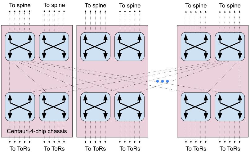
Experiences with Modeling Network Topologies at Multiple Levels of Abstraction

       Jeffrey C. Mogul, Drago Goricanec, Martin Pool, Anees Shaikh, Douglas Turk, Bikash Koley
                                   Google LLC, Mountain View, CA
                                                         Xiaoxue Zhao
                                                       Alibaba Group Inc.

Abstract                                                            tation of topology – a “model.” Such a representation needs
                                                                    to address multiple problems, including:
Network management is becoming increasingly automated,                  • Some management processes, e.g., capacity planning,
and automation depends on detailed, explicit representations              need to operate on abstractions, such as the amount of
of data about the state of a network and about an operator’s              future capacity between two cities (before we know
intent for its networks. In particular, we must explicitly repre-         how that capacity is implemented). Other processes, e.g.,
sent the desired and actual topology of a network. Almost all             configuration for routers, or fault localization, must op-
other network-management data either derives from its topol-              erate on low-level details (fibers, switches, interfaces,
ogy, constrains how to use a topology, or associates resources            SDN controllers, racks, connectors, etc.). Still other pro-
(e.g., addresses) with specific places in a topology.                     cesses, e.g., risk analysis, must reason about dependen-
   MALT, a Multi-Abstraction-Layer Topology representa-                   cies between abstract and physical concepts. Therefore,
tion, supports virtually all network management phases:                   we must represent multiple levels of abstraction, and
design, deployment, configuration, operation, measurement,                the relationships between them.
and analysis. MALT provides interoperability across our                 • In our experience, it is impossible for an unchanging
network-management software, and its support for abstrac-                 schema to successfully represent a constantly-changing
tion allows us to explicitly tie low-level network elements to            network, especially with frequent technical innovations.
high-level design intent. MALT supports a declarative style,              Therefore, the representation must support extensibility
simplifying what-if analysis and testbed support.                         and evolution as first-class features.
   We also describe the software base that supports effi-               • We must support constant change to our network, with
cient use of MALT, as well as numerous, sometimes painful                 many concurrent changes happening at once. We must
lessons we have learned about curating the taxonomy for a                 also support “what-if” analyses of options for future
comprehensive, and evolving, representation for topology.                 topologies. While humans often prefer an imperative
                                                                          style (“add this”, “move that”, “change that”), we have
1 Introduction                                                            found that using versioned sequences of declarative
                                                                          models removes a lot of complexity created by imper-
As our networks get bigger and more complex, we must au-                  ative operations. For example, with a declarative model
tomate all phases of network management. Automation de-                   we can validate the consistency of an entire network be-
pends on precise and accurate representations of the desired              fore committing a change.
and actual network. While network management requires                   • Different parts of our network follow different design
many categories of data, the most central is a representa-                and operational styles, managed by different teams. By
tion of desired or actual network topology. Almost all other              sharding our models on carefully-chosen boundaries,
network-management data either derives from topology, or                  we enable these teams to use their preferred styles with-
provides policy for how we want to create and use the topol-              out excessive interference. Sharding also improves con-
ogy, or associates resources (such as IP addresses or hard-               currency. At the same time, these shards do overlap, and
ware inventory) with specific places in a topology.                       we prefer, when possible, to use tools that work across
   At Google, we have learned the value of driving our                    our entire network, so a uniform representation en-
network management processes, from capacity planning                      sures interoperability.
through network design, deployment, configuration, opera-             This paper describes MALT (for Multi-Abstraction-Layer
tion, and measurement, using a common standard represen-            Topology), the representation we have developed for network

USENIX Association                           17th USENIX Symposium on Networked Systems Design and Implementation               403
topology, the software and processes we have built around                     work cost.
it, and the lessons we have learned. MALT’s primary goal is                      Consider an example where our demand forecast suggests
to provide a single representation suitable for almost all use-               adding capacity between two POPs. We construct candidate
cases related to network topology. Our path from “we need                     MALT models for each possible option for long-haul fiber
a uniform topology representation; how hard could that be?”                   spans, optical line system elements, and available router ports
to our current ecosystem has exposed that creating a coherent                 in those POPs. Then we compare options for incremental
set of design decisions, and getting this to work at scale, was               cost, lead times for hardware or fibers, and availability. We
much harder than we expected1 .                                               commit to one option, which becomes the planned MALT
    The main contributions of this paper vs. prior work are to                model, used to generate a detailed design and bill of materi-
explain the value of a multi-abstraction-layer representation                 als which is consumed by deployment teams.
that supports the full lifecycle of a network, and to expose                     Topology design for datacenter fabrics: Web-scale dat-
some pitfalls that await designers of similar representations.                acenter fabrics are far too large for us to directly manage
                                                                              each individual device. Our fabrics are structured as abstract
2 Uses for MALT                                                               blocks of switches [20]. We use MALT to describe the fab-
                                                                              ric in terms of these abstract blocks, their sizes, and policies
We model our global WAN [10], cloud-scale datacenter [20],                    governing how they should be interconnected. This abstrac-
and office-campus networks using MALT, including both                         tion makes it possible to reason about the topology. Once the
Software-Defined Network (SDN) and traditional network                        complete high-level design is determined, the abstract topol-
designs. Over 100 teams in Google and hundreds of engi-                       ogy is transformed mechanically into a fully concretized fab-
neers and operators use MALT regularly; we now require                        ric model, also represented in MALT, from which device con-
most systems working with network topology to use MALT.                       figurations and other management artifacts can be generated.
   Our uses have expanded over the past five years, and con-                  We maintain both the abstract and concrete representations
tinue to expand to new phases of network lifecycles, and to                   in MALT, to enable correlation between a given device and
new network types. A common theme across these uses is                        the abstract entity that generated it.
that they enable automation of diverse and interacting man-                      While we have many uses for MALT, our network manage-
agement processes, through a uniform representation of the                    ment processes often use data that is not about topology, and
intent for, and structure of, our current and future network.                 for which we use other abstract or concrete representations;
   Broadly, our primary uses for MALT have been in three                      § 8 discusses what we exclude from MALT.
areas: operating our user-facing WAN; WAN capacity plan-
ning and design; and datacenter fabric design and operation.                  2.1 Motivations for MALT
   Operational management of user-facing WAN: We use
MALT when configuring network elements, managing the                          The use cases above illustrate three motivations for MALT:
control plane of an in-service network, and monitoring the                      • Support for the full lifecycle of a network: As de-
network for failures and other behaviors. We represent the                        scribed above, we use MALT models for capacity plan-
network’s “as-built” state in a MALT model in which all                           ning, reliability analysis, high-level and detailed design,
entities related to device management, including routers, in-                     deployment planning and auditing, and as one kind of in-
terfaces, links, Points of Presence (POPs), etc, are visible                      put to the generation of device and SDN-controller con-
to management workflows, which only operate by updat-                             figuration. MALT also supports our monitoring, band-
ing this model, and never by directly updating devices. An                        width management, and some debugging operations. We
API supports specific, well-defined update operations on this                     regularly find new uses, often without having to make
model; all updates are validated before being used to gener-                      major schema changes.
ate the corresponding device configurations. Operations in-                     • Uniformity: Prior to adopting MALT, we had many sys-
clude adding devices or links, or changing device (entity) at-                    tems that maintained representations of network topol-
tributes to control monitoring and alerting.                                      ogy for their own uses. These systems often have to
   WAN capacity planning and design: We must explore                              exchange topology data. Without a single, uniform rep-
many options for evolving network capacity to meet pre-                           resentation, this leads not only to O(N 2 ) translations,
dicted demands. MALT’s support for multiple layers of ab-                         but also the potential for data loss or ambiguity, both
straction, including layer-1 elements (e.g., fiber cables and                     of which make real automation nearly impossible. Uni-
transponders) and layer-3 elements (routers, line cards, etc.),                   formity also allows hundreds of software engineers to
allows simulation of each option against specific failure mod-                    write interoperable systems without massive coordina-
els, so that we can jointly optimize failure resilience and net-                  tion overheads (which also tend to grow as N 2 ).
                                                                                • Multiple levels of abstraction: Many design, operation,
     1 While many enterprise networks are smaller than Google’s, we believe       repair, and analysis processes require a clear understand-
that MALT’s approach would also be beneficial at much smaller scales.             ing of the relationships between high-level design intent

404    17th USENIX Symposium on Networked Systems Design and Implementation                                            USENIX Association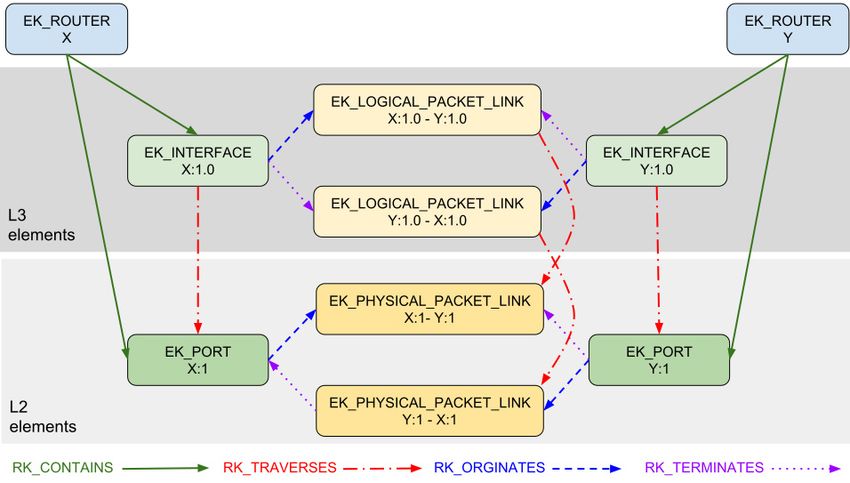
and low-level realizations. For example, when we ana-
     lyze a WAN plan to understand whether it will meet its
     availability SLO [1], we need to know the physical loca-
     tions of the underlying fibers – e.g., whether two fibers
     run across the same bridge or under the same cornfield.
     MALT allows us to explicitly represent these abstrac-
     tion relationships (see §3.3), which allows software to
     operate on data, rather than relying on inference.

2.2 Support for the entire network lifecycle
We present some illustrations of how we could use MALT
models for various points in the lifecycle of our networks.
   Consider a WAN with 10gbps capacity between London
and Paris, which want to increase to 20gbps. Such increments
often take months, so we start by creating a model 1 (see
Fig. 1) of our WAN for (say) 6 months from now, with this
capacity set to 20gbps. We then look for available subma-
rine and terrestrial cable capacity that collectively provides
an additional 10gbps between the two cities. There might be
several possible cable paths, so we can create “what-if” 2            Figure 2: Multiple MALT models for a capacity expansion
models for each option, and then analyze each option with            Now consider a datacenter capacity expansion (see Fig. 2).
respect to costs, lead-times, and historical failure probabili-   Because we expand live networks [23], we must split up the
ties, before committing to a “plan of record” (POR) model         physical changes into multiple steps, to maintain capacity
 3 for the WAN connectivity.                                      headroom – e.g., an 8-step procedure should reduce capac-
                                                                  ity by at most 12.5% per step. For each step, we generate an
                                                                  intermediate model 5 , which we subject to an an automated
                                                                  “drain-impact analysis” just before executing the step. This
                                                                  analysis uses two additional models: the current link utiliza-
                                                                  tions 6 to estimate near-term future demands, and a model
                                                                  representing failed links 7 to account for their impact on
                                                                  available capacity.2
                                                                     Once a step is ready, we trigger the human operations to
                                                                  carry it out. Humans are fallible, and so is hardware, so be-
                                                                  fore “un-draining” the new links, we audit the work, via both
                                                                  automated and manual checks. In some cases, we might de-
                                                                  cide that an error (e.g., using the wrong patch-panel port) is
                                                                  harmless, but to avoid further confusion, we update a model
                                                                   8 of the “as-built” network, so that future changes will not
                                                                  conflict with reality.
                                                                     After the new hardware is deployed, we must update router
                                                                  configurations. Rather than having humans do that, we auto-
                                                                  generate all such “config” from MALT models and other
                                                                  meta-information [12]. We also use these models to auto-
      Figure 1: Multiple MALT models for WAN planning             generate configurations for our SDN control plane.
                                                                     While many of the processes in Figs. 1 and 2 operate on
    Then we must choose endpoint equipment (routers, opti-        the entire graph of a WAN or datacenter network, others use a
cal line systems, etc.) and either ensure we have enough free     query API (§ 6). For example, the wire-list generator (Fig. 2)
ports on existing equipment, or order new systems; again,         can query to extract just a set of switch ports and their loca-
we often explore multiple options (different vendors, differ-     tions, while ignoring most of a model.
ent router configurations, etc.) before choosing a final POR         Automation: We asserted a goal of ubiquitous automation.
model 4 that covers both WAN links and terminating equip-         In fact, we have not yet automated every step shown in Fig. 1,
ment. (This also includes ensuring that routers can physically
fit into available racks, and that we have enough power and          2 In practice, we merge 6 and 7 into a single input, also critical to our

cooling.)                                                         Bandwidth Enforcer system for online WAN-bandwidth allocation [13].

USENIX Association                          17th USENIX Symposium on Networked Systems Design and Implementation                         405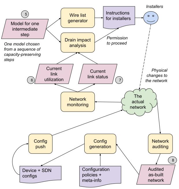
but most of Fig. 2 now uses MALT-based automation. Full               • the “state” of an entity: is it planned? deployed? con-
automation requires disciplined, hard work; MALT’s goal is               figured? operational? faulty? under repair? etc. (We de-
to enable that work, not to make it happen by magic.                     fined a uniform “state machine,” although adopting this
                                                                         standard ubiquitously has been challenging.)
2.3 Antecedents to MALT                                               • the index of an entity within its parent (e.g., “this is
                                                                         linecard #3 within the containing chassis”).
Our efforts to model network topology started with various            • IP addresses and VLAN IDs assigned to interfaces – use-
independently-developed, non-interoperable representations               ful when generating device configuration.
– not through a conscious decision, but because each of mul-          • the maximum capacity (bits per second) for elements
tiple teams realized they needed topology modeling. E.g., we             such as ports and links – useful for capacity-planning
had one way to represent datacenter and B4 WAN [10] net-                 and traffic engineering.
work designs (Fig. 2, 5 ), and an entirely different representa-   but attributes can be rather arcane, such as one meaning “dur-
tion, to support bandwidth allocation [13], for link status and    ing the transition from IPv4 to IPv6, this network requires
utilization (Fig. 2, 6 + 7 ); the necessary format conversion      hosts, rather than switches, to perform 6to4 decapsulation.”
was hard to maintain. Other teams maintained database-style           A complete MALT “model” consists of a set of entities
records for each WAN router, but resorted to spreadsheets          and a set of relationships between those entities. A model
or diagrams to represent WAN topology, without machine-            also includes some metadata, such as the provenance of the
readable abstractions tying capacity intent (Fig. 1, 1 ) to spe-   model (what software created it, when, and from what inputs)
cific links (Fig. 1, 4 ).                                          and its profile(s) (§3.5).
   The lack of abstraction and interoperability between these         Fig. 3 shows a trivial example of a MALT entity-
formats created significant complexity for our operations and      relationship (E-R) graph, depicting a connection between
software. While MALT has not entirely eliminated that com-         two routers. Each router contains one L3 interface and an L2
plexity, it gives us a clear path.                                 “port” for that interface. The interfaces are connected by a
                                                                   pair of unidirectional L3 “logical packet links” that each tra-
3 The MALT representation                                          verses, in this case, a single L2 “physical packet link.” (Link
                                                                   entities in MALT are always unidirectional, which means
We chose to use an “entity-relationship model” representa-         that they usually come in pairs.)
tion for MALT. (In § 5.3 we explain why we chose not
to expose a relational database). In an entity-relationship
model, entities represent “things,” which have have “kinds”
(types), names, and attributes, Entities are connected via re-
lationships, which (in MALT) have kinds, but neither names
nor attributes. MALT uses a somewhat simplified form of the
classic entity-relationship model [4].
   Our current schema has O(250) entity-kinds, including
(among many other things) data-plane elements, such as
packet switches, switch ports, links between ports, etc.;
control-plane elements, such as SDN controller applica-
tions, switch-stack “control points” (local control planes),
machines for SDN controllers, etc. “Sheet-metal-plane” el-
                                                                           Figure 3: Trivial MALT entity-relationship graph
ements, such as racks, chassis, and line-cards. Designing, cu-
rating, and evolving this taxonomy has been challenging; we
                                                                      Note that the E-R graph is not isomorphic to the network
discuss our experiences in § 9.
                                                                   graph – links in the network are represented as nodes (enti-
   We have a set of about 20 relationship-kinds, including
                                                                   ties) in MALT’s E-R graph.
“contains” (e.g., a line card contains a packet-switch chip),
                                                                      Appendix A provides a more detailed example, showing
“controls” (e.g., an SDN controller application controls a
                                                                   how we model a datacenter network.
switch’s local control plane), and “originates” (e.g., a link
originates at one port, and terminates at another).
                                                                   3.1 Entity-IDs
   By convention, we name entity-kinds such as
EK_PACKET_SWITCH and EK_RACK, and relationship-kinds               MALT entities have entity-IDs composed of an entity-
such as RK_CONTAINS and RK_ORIGINATES.                             kind and an entity-name. E.g., in Fig. 3, one router
   For each entity-kind, we define a set of attributes. Some       has an entity-ID of EK_DEVICE/X and one link’s ID is
entity-kinds have lots of attributes, some have only a few.        EK_PHYSICAL_PACKET_LINK/X:1-Y:1. Entity-IDs must be
Typical attributes include:                                        globally unique, with respect to an implicit namespace that

406   17th USENIX Symposium on Networked Systems Design and Implementation                                   USENIX Association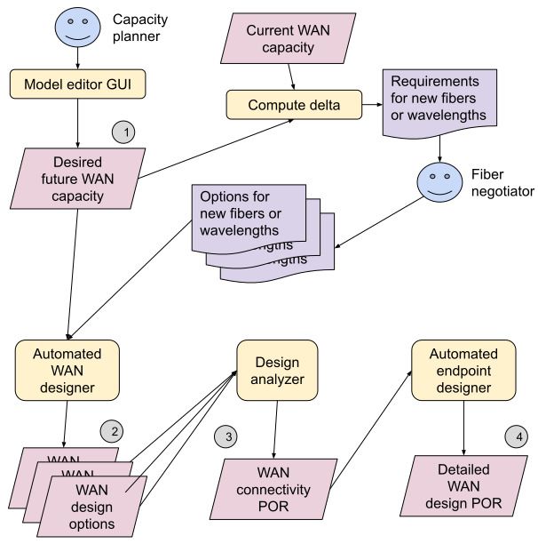
(by default) covers all of Google, and within a single “snap-       trunking to individual L2 links, and through four or five lev-
shot” view of our modeling data (we will clarify this concept       els of optical-transport-network hierarchy [22, fig. 12].
in § 4).                                                               We also have relationship-kinds that help with abstraction:
   While we typically use human-sensible names for entities,           • RK_CONTAINS for hierarchical containment.
this is not necessary for automated systems (although it sim-          • RK_AGGREGATES to indicate, for example, which single-
plifies debugging!). We have learned (from rather bitter expe-            ton links are aggregated into a trunk link, or which
rience) to ruthlessly ban any code that parses an entity-name             packet switches are aggregated into a logical switch.
to extract any meaning; instead, the attributes defined for an         • RK_TRAVERSES: e.g., an end-to-end MAC (L2) link is
entity-kind should encode anything that could be extracted                constructed from the ordered traversal of a series of L1
from a name. (§11.4 discusses why using names in entity-                  links connected by splices and patch panels.
IDs might not have been the best decision.)                                                             Fig. 4 shows how we
                                                                                                     can use multiple layers in
3.2 Allowed relationships                                                                            WAN planning. The top layer
                                                                                                     shows two WAN tunnels (as
The complete MALT schema consists of a set of entity-kinds
                                                                                                     in B4 [10]) between POPs B
(with attributes), a set of relationship-kinds, and a set of al-
                                                                                                     and C, including one via A;
lowed relationships. For example, we allow a packet-switch
                                                                                                     the middle layer shows how
to contain a port, but not vice-versa. These rules constrain
                                                                                                     these tunnels map onto L3
producers, but this is good, because it means that model-
                                                                                                     router adjacencies; the bot-
consuming code need not handle arbitrary relationships.
                                                                                                     tom layer shows how the L1
   Relationships can be directed or bidirectional, and 1:1,
                                                                                                     fiber path for the B − C L3
1:many, many:1, or (rarely) many:many. We currently allow
                                                                    Figure 4: Layered abstrac-       adjacency  runs through POP
about 700 relationships between pairs of entity-kinds; this is
                                                                    tions in WAN planning            A. This  means that the A − B
a small subset of the millions that could be constructed, but
                                                                                                     fiber path has become a sin-
we only allow those that support sensible abstractions (a sim-
                                                                    gle point of failure (SPOF) Because MALT includes all of
ple form of static validation).
                                                                    these abstractions (abstract flows, IP adjacencies, fiber paths)
                                                                    in the same model, with explicit relationships between them,
3.3 Multiple levels of abstraction                                  we can easily map this SPOF back to the tunnels it affects.
While MALT’s primitive entity-kinds, including those listed
above but also others, are sufficient to describe a wide vari-      3.4 Machine- and human-readable formats
ety of networks, one of the motivations for MALT was that
it should allow us to represent multiple levels of abstraction      Since MALT is designed to support automation, we normally
and the relationships between them. Some use cases, for ex-         represent models in a binary format compatible with RPC
ample, involve refining highly-abstracted designs into more         interfaces. However, developers occasionally need to view
concrete ones, but we also may need to reverse an abstraction,      (and less often, edit) models or individual components, so
and ask (for example) “what abstract thing does this concrete       we can convert between binary and a textual format. We also
thing belong to?”.                                                  have a “shorthand” format for concise text-based representa-
   We typically create abstraction via hierarchical groupings,      tion; this is especially useful for creating test cases.
such as entity-kinds for:
    • logical switches: sets of primitive switches, intercon-       3.5 Profiles
      nected (e.g., as a “superblock” in a Jupiter [20] network)
      so that they provide the illusion of one larger switch with   While we have just one “global” MALT schema, which pro-
      more ports than any single switch.                            vides uniformity across all of our networks, we have found it
    • trunk links: parallel sets of links that provide more         useful to introduce profiles, which restrict how the schema is
      bandwidth than a single physical link.                        used. We use profiles for purposes including:
    • control domains: sets of elements controlled by one              • To specialize the schema for certain network types. For
      replica-group of SDN controllers.                                  example, the profile for a data-center network might as-
    • Geographic elements: a hierarchy of, e.g., cities, build-          sert that the uplinks from aggregation switches are al-
      ings, and spaces within buildings.                                 ways connected to the downlinks from spine switches,
    • Dependencies: sets of entities that could fail together            while the profile for an office-campus network might as-
      (due to SPOFs, or to sharing a power source) or that               sert that there is always a firewall between the public
      must be kept diverse, to avoid accidental SPOFs.                   Internet and the campus network.
For a WAN, the layering can be quite deep, starting with               • To support evolution, via profile versioning. As we dis-
highly-abstracted city-to-city links, through several levels of          cuss in §10, we are continually evolving both the global

USENIX Association                           17th USENIX Symposium on Networked Systems Design and Implementation              407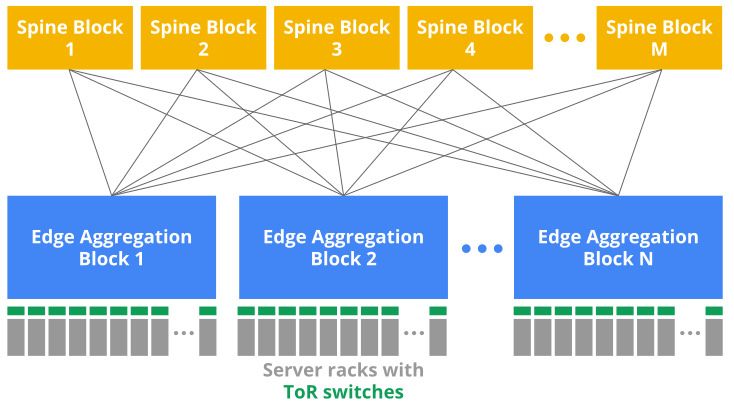
schema and our profiles, which sometimes means chang-               (§10 covers evolution in detail.)
      ing the way we represent a concept; we need to en-                • Performance: A single model of our entire network
      sure that model-producers and model-consumers agree                 would be too large to fit in the memory of a single server.
      on which representation is in use.                                  Also, while many applications extract small sub-models
   • To decouple the release cycles of complex graphs of                  from storage via query RPCs, some do need to retrieve
      software systems, so that model producers can move for-             larger subsets; using a “Get” RPC to retrieve one or a
      ward without forcing all model consumers to migrate at              few shards is a lot more efficient. (However, if we use
      the same time.                                                      too many shards, that leads to per-shard overhead; we
A profile is, in effect, a contract between a producer and a              try to strike a good balance.)
consumer. We defined a machine-readable profile specifica-              • Protection and fault domains: All software has bugs,
tion, which allows us to mechanically check that a model ac-              and we must defend against security breaches; sharding
tually meets one more or profiles (as asserted, by the pro-               allows us to limit the damage from a faulty program, and
ducer, in the model’s metadata).                                          it allows us to set ACLs that restrict users to the shards
   A profile is identified by its name (e.g., “Jupiter”), a major         they actually need. (For example, someone operating on
version number, and a minor version number. If we make an                 a edge router in Paris does not need access to a datacen-
incompatible change, such as inserting a new structural layer             ter switch in Rome.)
that turns a one-hop relationship path into a two-hop path, we          • Lifecycle stages: We use several sets of shards to rep-
need to increment the major version.                                      resent distinct points in the lifecycle of a network: e.g.,
   If two profile-IDs differ only in their minor-version num-             planning, deployment, and operation.
bers, this implies backward-compatibility: a model with                 • Alternative universes: We need to represent not just
the higher minor-version can be read safely by a con-                     a single timeline, but alternative future designs for our
sumer already tested against the lower version. The converse              networks – e.g., to analyze multiple options for purchas-
does not apply; models with an out-of-date minor version                  ing WAN connectivity or multiple orderings for capac-
might be missing information that recent consumers expect.                ity augments. We especially need to create isolated uni-
(§10 discusses how hard it has been to define “backwards-                 verses for testing software and operational procedures.
compatible” in the face of certain coding practices.)                  Model sharding requires some support from the query
   Machine-checkable profiles can express constraints nar-          mechanism; §6.2 describes our “multi-shard query” (MSQ)
rower than the entire schema; for example, we can require           API. It also sometimes requires the same entity to appear in
that certain relationships are present (or not present), or that    multiple shards (so that no shard has dangling relationships);
certain attributes have values within a constrained range.          to avoid violating our uniqueness rule for entity-IDs, we add
However, our current profile-specification language is not ex-      “linkage” metadata to these repeated entities. Linkage allows
pressive enough to represent certain global policies, such as       us to unambiguously resolve these repeated entities.
“no IP address may be assigned to two different interfaces”            Note that, as discussed in §5, each update to a shard creates
— we validate that using other means.                               a new “instance” or version. This is another dimension in
                                                                    which we have many shards.
                                                                       Given our heavy use of sharding and instances, we need a
4 Division into multiple shards
                                                                    way to specify a version-consistent snapshot that spans mul-
One might imagine a single model for Google’s entire collec-        tiple shards; §5.2 describes the “model set” abstraction that
tion of networks, but we actually divide this data into thou-       supports this.
sands of MALT model “shards,” for many reasons:
   • Separation of ownership: Many teams contribute to              5 MALT storage
     the design and operation of our networks; things are
     much simpler when we shard models, so that each shard          While one might consider treating MALT as a database
     has a single owner. Such sharding clarifies responsi-          schema, we instead choose to think of a set of MALT enti-
     bility, and can avoid the need for complex consistency-        ties and relationships (i.e., a shard) as a named value. One
     maintenance protocols.                                         can think of a MALT shard as a file; in fact, we can store a
   • Distinct profiles: Different parts of our overall network      shard as a file, either in binary or in a human-readable format.
     conform to different profiles (§3.5); sharding allows us          We prefer to store shards in a purpose-built repository,
     to cleanly associate a profile with the data that it covers.   MALTshop, that provides several important features:
   • Profile evolution: We cannot change all software instan-          • It is logically centralized, with a single UNIX-like
     taneously when introducing a new profile version; in-               namespace for shards, so we know where to look for
     stead, we support old versions for a phase-out period.              any shard (past, present, or future). MALTshop main-
     This means that we must represent the same informa-                 tains statistics and logs, making it easy to discover who
     tion using multiple profiles, stored as per-version shards.         is using the shards and what features are in use.

408    17th USENIX Symposium on Networked Systems Design and Implementation                                   USENIX Association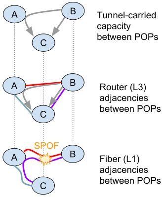
• It has a distributed, highly-available implementation.        an MSID between systems, rather than lists of instance IDs.
   • It provides a basic Get/Put/Patch API, but most model-        The metadata service allows applications to find the latest
     reading code employs its Query API (see §6).                  MSID, or to look up an MSID based on various attributes.
   • Shards are versioned; each update (via a whole-shard
     Put or diff-based Patch API) creates a new, immutable         5.3 Discussion: dataflow rather than database
     instance, which is permanently bound to a sequence            Given our ability to efficiently store (and thus share) im-
     number (but can be mutably bound to a named label).           mutable versions of MALT shards, it is convenient to think of
     Small updates are efficiently implemented via copy-on-        a single shard instance as a value – a snapshot of a database,
     write, so the cost of creating and maintaining many ver-      rather than a mutable instance of a database. While these val-
     sions of a large shard can be relatively low.                 ues can be quite large, and in many cases an application is
   • The repository supports ACLs on shards, which pro-            only interested in a small subset of a shard, this approach
     vides the basis for security mechanisms. We have not          allows us to construct many network management pipelines
     found a need to bear the burden of ACLs on individual         as dataflow graphs, where streams of MALT shard instances
     entities; those could be layered above MALTshop in an         flow between stateless functional operators.
     application-specific service, if necessary.                      We use these dataflow graphs primarily for planning, de-
                                                                   sign, and analysis applications – systems that operate the ex-
5.1 MALTshop implementation details                                isting network do use MALT imperatively (see §11.2). Also,
MALTshop stores its state in Spanner, a reliable, consistent,      once the planning process must trigger actions with expen-
distributed SQL database [6], which handles many of the            sive effects (e.g., ordering or installing hardware), we must
harder problems. The SQL schema has tables for shards, in-         use imperative operations – isolated to separate shards.
stances, entities, and relationships; an entity’s attributes are      Why not just represent a network topology as a relational
stored as a SQL blob. Updates to the MALT schema do not            database, as is done in many other systems (for example,
require changes to the SQL schema.                                 COOLAID [5])? Some of our previous systems were indeed
   While our initial SQL schema supported a simple imple-          implemented as RDBMSs, with SQL queries. In our experi-
mentation of MALTshop, as usage increased we realized that         ence, an RDBMS worked nicely for simple use cases, but:
the schema did not always support good performance, and                • an RDBMS by itself does not provide clear patterns
read-modify-write operations made it tricky to avoid corrup-             for new types of abstractions or their graph-type rela-
tion when a server failed. We are now migrating to a new                 tionships (aggregation, hierarchy, etc.). When we used
SQL schema that should improve performance and data in-                  an RDBMS, we effectively imposed an implicit entity-
tegrity; the details are too complex to describe in this paper.          relationship schema; why not just make that explicit?
Because the SQL schema is entirely hidden from all applica-            • a first-class abstraction of individual shards makes it
tions, this migration is transparent to all users.                       much simpler to express per-shard profiles, versioning,
   MALTshop uses several kinds of cache, including a client-             labels, access controls, and retention policies. It also
side cache library that currently supports only “Get” oper-              make it easier to reason about how these shards flow
ations, but ultimately should reduce many RPC round-trips,               from one system to another – for what-if analysis and
and a server-side cache that greatly reduces the cost of com-            isolated software testing, or to parallelize datacenter-
puting diffs between two recent instances of a shard (an op-             expansion projects (as in Fig. 2).
eration some of our applications use heavily).                         • layering our MALT schema over an SQL schema makes
   MALTshop, due to Spanner’s scalability, itself scales well.           it simpler to do “soft deprecation” of entities, relation-
We currently store thousands of shards, each with many ver-              ships, and attributes, without having to impose those
sions; the largest shards have millions of entities and millions         changes on older shard instances or their users.
of relationships. Occasionally MALTshop serves thousands               • layering MALT over SQL makes it easy for us to change
of queries per second, but usually the load is lower.                    the SQL schema, for better performance, without requir-
                                                                         ing any client changes.
                                                                       • we can also provide the MALTshop API (albeit with lim-
5.2 Model sets
                                                                         ited performance) on top of a simple file system, which
Because we shard our models extensively, and each shard                  is useful for disaster-recovery scenarios when Spanner
may have many instances (versions), operations that span                 might be down or unreachable.
multiple shards need a way to specify a consistent snapshot,       None of these are impossible in SQL (manifestly, since
which we support with a “model set" abstraction. When a            MALTshop expresses all of these with an underlying SQL
model-generator creates a set of shard instances, it also ob-      schema), but by hiding the SQL schema from clients via
tains a new “model set ID" (MSID), and uses a metadata ser-        MALT’s abstractions, we make our clients far less brittle.
vice to register a binding between the MSID, some attributes,      Overall, we have found the dataflow approach far easier to
and its constituent shard instances. We therefore usually pass     reason about, and in some cases, more efficient. In a few

USENIX Association                          17th USENIX Symposium on Networked Systems Design and Implementation              409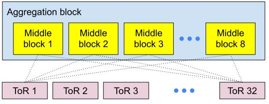
real-time applications (e.g., SDN controllers), we do express       querying in-memory shards, as shown in Fig. 5; SQL would
a network’s topology in a private, purpose-built, in-memory         not support that.
database (with update-in-place).                                       In our current language, a query is expressed as a sequence
   Other graph-processing systems likewise have avoided             of commands. Each command operates on a “frontier” of ac-
RDBMSs, for reasons such as articulated by Hunger et al. [9]        tive “nodes,” which (approximately) are references to enti-
and for Pregel [16].                                                ties. Query commands can move the nodes around the input
                                                                    model3 along relationship edges. As each active node moves
                                                                    around the input model, the query execution engine keeps
6 Querying MALT models
                                                                    track of the path it took.
While our model-producing software tends to generate an en-            The output is one or more result models, optionally anno-
tire shard in one operation, our model-consuming software           tated with labels, which includes all active nodes at the end
generally does not operate on all entities in a shard, but rather   of the query, plus the full path they took (relationships and
only on small subsets. In this respect, our software differs        stepped-over entities) to get to their final position. Some com-
from traditional graph-processing algorithms [16]. (There           mands remove (“prune”) active nodes; these also generally
are exceptions: systems for drain-impact analysis, or WAN           remove, from the result, earlier entities that the node previ-
cost optimization, do look at entire networks.)                     ously visited, if not also visited by another path.
    Model consumers extract subsets that meet some predi-              Queries always start with a find command, which looks
cate via a query language, which walks an entity-relationship       at all entities in the input model, subject to constraints such
graph to extract a chosen subset model. Typical queries             as an entity-kind and/or some attribute values; e.g.:
might be of the form “find all of the top-of-rack switches          find EK_PACKET_SWITCH/tor17
in datacenter X”, “find the switches managed by SDN con-            to start the query at a packet switch named “tor17”, or
troller Y”, “find all the cable strands that share connector C”,    find EK_VLAN { id: 13 }
or “given port P1 on switch S1, find the corresponding port         to start the query at all VLANs with a VLAN-ID of 13.
P2 on switch S2 such that P1 is connected to P2.”                      Queries often involve following relationships, e.g.:
    Designing a query language for MALT has been surpris-
                                                                    find EK_PACKET_SWITCH/tor17
ingly hard; we are on our second language (and we also toyed          until RK_CONTAINS EK_PORT
with the idea of using a Datalog-style language). Our first
                                                                    to return all of the ports contained in that switch.
query language was sufficient, but it was often hard for users
                                                                       The language includes many other commands; we lack
to understand how to express a correct and efficient query.
                                                                    space to describe the full language.
Our second language is easier to use, because it operates on
                                                                       Query implementation: Queries traverse relationships
paths through the E-R graph, rather than sets of entities; paths
                                                                    in a model, marking paths to keep or prune. For complex
are the more natural abstraction.
                                                                    queries, this may require many iterations through the model.
    Sometimes it is difficult or impossible to use a single query
                                                                       Queries can be executed locally in-memory, or remotely
to return exactly the right subset; this leads to a pattern
                                                                    by MALTshop. For locally-indexed models, these itera-
where the application issues a remote query to retrieve a
                                                                    tions are inexpensive. However, MALTshop has to translate
larger-than-desired sub-model, and then applies a local (in-
                                                                    queries into repeated calls to its SQL database. To make this
memory) query to further refine the results. In some cases,
                                                                    efficient, the query engine requests SQL data in batches.
it is simpler, or even necessary, to post-process the query re-
sults using a traditional programming language.
    Sometimes people ask                                            6.1 “Canned queries”
“if that’s so hard, why not                                         Queries that are simple to state in English may turn into long
just use SQL?” MALTshop                                             sequences of commands. These have proved challenging to
effectively compiles MALT                                           write, for many of our users. They can also be fragile with
queries to SQL queries, so                                          respect to profile changes; when complex, profile-dependent
on the one hand: sure! but                                          queries are scattered across code owned by many developers,
on the other hand, these SQL                                        profile change inevitably leads to bugs. Therefore, we have
queries are substantially                                           a library of “canned queries.” When a profile owner creates
more complex, and also                                              a new profile version, that engineer is also responsible for
deeply depend on the under-                                         creating (and testing!) a new version of any canned query af-
lying SQL schema, which                                             fected by that change. This gives the responsibility for man-
we do not want to expose               Figure 5: Query layering     aging complex queries to the experts on the underlying rep-
to applications (because we                                         resentations.
have already had to revise it several times.) We also want to
use the same language for both MALTshop and efficiently                3 That   is, change the binding between an active node and an entity.

410    17th USENIX Symposium on Networked Systems Design and Implementation                                           USENIX Association
We define canned queries as needed. For example, one At each step in such a dataflow graph, we can apply our au-
canned query might return all of the L2 links between a given tomatic profile-checker (§3.5) to detect some software bugs
pair of switches; another might return the rack where a given or incomplete inputs.
line card is located (useful when trying to repair that card).
7.2 Model-visualization systems
6.2 Multi-shard queries While MALT is designed to support automation, humans of-
As described in §4, we split the representation of our entire ten need to look at models. We have visualization systems to
network into many sets of shards. However, some applica- support two distinct use cases:
tions would like to form queries that span shard boundaries. • Network visualization: Network operators, capacity
Also, we want the freedom to revise our sharding plan (we planners, and customers want to visualize their network
have done this several times), and we do not want model- topologies, without knowing how these are represented
consuming code to depend on that plan. Therefore, most ap- in MALT. Our network visualizer GUI displays network
plications that query MALTshop actually use a multi-shard nodes and the links between them, with statistics and
query (MSQ) API, which allows a query to specify a set other attributes, and lets a user zoom between abstrac-
of shard pathnames (using wildcards), rather than a single tion levels. MALT’s inherent support for multiple levels
shard; MALTshop then executes the query against a view of abstraction made this tool easier to write.4
composed of those shards. • Model visualization: Developers of MALT software
MSQ is efficient, because MaltShop’s underlying SQL and models want to visualize the structure of their mod-
schema has an index that identifies entities appearing in mul- els, rather than of the network. Our MALTviewer allows
tiple shards, and limits the queries to only those shards. Per- them to navigate through entity-relationship graphs,
forming MSQ in-memory is not feasible, due to the size and with integral support for the MALT query language.
time it takes to load and index all the shards. We considered developing a GUI-based tool to create and
The introduction of MSQ significantly simplified many edit MALT models, but so far, creating models by expansion
applications. For example, prior to MSQ, code looking for of concise, high-level intent (as in §7.1) has sufficed.
“peer ports” at the boundaries between datacenter and WAN
networks had to issue separate queries in multiple shards, us- 8 What does not belong in MALT?
ing the output of the first query to compose the second one.
Also, the code had to know which specific shards to query. While MALT is central to our network management sys-
Code using MSQ does this in one query, and knows much tems, we do not believe it should be extended beyond ex-
less about shard boundaries. pressing topology. People have sought to add other kinds of
network-management data (sometimes just to exploit MALT-
7 Software infrastructure shop rather than investing in another storage system), but
these typically do not fit well into an entity-relationship
In addition to MALTshop (§5) we have developed a library schema. Other categories deserve more-appropriate represen-
to provide common functions for MALT developers, and ad- tations, including:
ditional software to help us use and manage MALT models. • Generated configuration for devices and SDN con-
trollers; our config generators read MALT models, but
7.1 Model-generation systems their output data belongs in OpenConfig YANG mod-
els [18]. We built a “ConfigStore” service more suited
We do not want humans to create detailed models via di- to this use case than MALTshop is, because access pat-
rect editing; this would be tedious and unreliable. Instead, terns (especially queries) to “config” are quite different.
humans generate highly-abstracted representations (typically • Policies for how to use the network topology, such as
via GUIs or text editing) that become input to model- BGP policies. We believe these are most accessible to
generation software that produces concrete models. We the operators who manage these policies when they
sometimes do this in multiple steps, where the MALT output are expressed using a configuration representation, such
from one step becomes the input to future steps. At each step, as OpenConfig or a vendor-specific one. We allowed
the models become more detailed, based on late-bound de- some early users of MALT to embed BGP policies in
sign decisions and/or more-specialized profile-specific code. the schema, but that proved to be awkward and com-
We have been migrating to a “declarative dataflow” ap- plex. (Alternatively, Propane [2] is a domain-specific
proach to model generation (as in Figs. 1 and 2), away from language for expressing BGP policy.)
early systems that used imperative inputs (“add this switch”) 4 A similar tool allows us to visualize the network overlaid onto a geo-
and that packaged all model-generation steps into one exe- graphic map; this is especially useful for planning WAN and campus links
cution. Imperative, non-modular systems (not surprisingly) that must avoid single points of failure. However, this tool still gets its data
turned out to be hard to maintain, evolve, and test. from a predecessor to MALT.
USENIX Association 17th USENIX Symposium on Networked Systems Design and Implementation 411• Abstracted forwarding tables (AFTs) that represent schema designers, who could take a company-wide and long-
the observed FIBs in our network; these are useful for term view of proposed changes. Prior to establishing the
applications such as Traffic Engineering and our Band- MRB, the schema accreted many ad hoc, inconsistent, or du-
width Enforcer system [13], and for techniques such as plicative features. Using a multi-person board, rather than a
Header Space Analysis [11]. AFTs are similar to Open- single owner, to review schema changes also allows us to par-
Flow [17] rules, and might be suitable for representing allelize the work, and to maintain consistency as employees
ACLs, although today we use a DSL for ACLs. come and go. We also have a written “style guide,” both as
• Allocated resources, such as IP addresses, Autonomous advice to engineers proposing schema changes, and to guide
System Numbers (ASNs), and ports on switches and new MRB members. However, our weekly MRB meeting
patch panels. Since we must not allocate any one of constantly finds new issues to debate at length.
these resources to multiple “owners,” these are best rep-
resented in a database that supports modify-in-place op- 9.1 Orthogonality
erations, exactly what we would rather not do for declar-
ative topology models. We value uniformity: we want our tools to process models for
• Inventory, including support for SOX compliance and many different kinds (and generations) of networks, without
other finance-related applications. Often these records lots of special cases. Sometimes this is straightforward; the
exist before we have a topology to place them in. MRB often prevents proposals attempting to create a new
• Monitoring data from SNMP and similar systems. entity-kind (EK) for an existing concept, or a narrower-than-
MALT is not efficient at representing time-series data, necessary proposal for a new concept.
and Google already has robust, massively-scalable sys- We also value simplicity; initially we thought this meant
tems for monitoring and alerting, so while we do distill that we should be conservative in creating EKs. However, we
some data from monitoring pipelines to correlate it with learned that overloading one entity-kind with concepts that
topology, as in Fig. 1, we do not use MALT as the pri- are not similar enough leads to the use of subtypes (expressed
mary representation for this data. as attributes), which creates complexity in model-consuming
We tie these representations together using foreign keys, in- code and in the formulation of queries.
cluding MALT entity-IDs (e.g., an AFT is tied to a particular We developed two tests to define “similar enough?”:
MALT “control point”). • Do the various use cases share the same relationship
It can be tricky to define a bright line between “topology” structure, or would one expect different relationships
(appropriate to represent in MALT) and non-topology data. based on the subtype? If the latter, we prefer to use a
Partly this is driven by a need to store some information distinct (“orthogonal”) EK for each use case, rather than
in two places, for efficiency and availability – for example, having a kitchen sink of relationships for an EK.
we allocate blocks of IP addresses from an IP-address DB, • Do the use cases mostly share the same entity attributes,
and then record these blocks in MALT models as attributes or are there several mostly-disjoint subsets of the at-
of subnetwork entities. However, when we debate “does this tributes, based on subtype? If the latter, we prefer mul-
data belong in MALT?” the usual reason for the complexity tiple EKs. (Subtyping violates the “prefer composition
of the debate is that we had not quite got our taxonomy right; over inheritance” principle.)
relatively few cases have been truly hard calls. These are not rigid rules. Sometimes we must guess about
future use cases, or just make an arbitrary decision.
An example of why we need these rules: we initially de-
9 Schema design principles and processes fined EK_PORT to refer to singleton ports, trunk ports, VLAN
ports, and patch-panel ports. This “simple” structure leads
The MALT schema must allow us to represent a broad va- to models where a VLAN EK_PORT can contain a trunk
riety of network designs completely and consistently; code EK_PORT which can contain multiple singleton EK_PORTs
with special cases for different structures is likely to be unre- – and queries on ports have a lot of complexity to distin-
liable and hard to maintain. Schema design turned out to be guish which subtype they care about. We ended up with over
harder than we expected; we have learned several principles 60 possible relationships involving EK_PORT, and about the
that were not obvious to us at the start. We could not create same number of attributes, most of which are never used to-
good abstractions a priori for a complex, evolving set of net- gether (which makes it hard to check whether a model pro-
works, but had to test and refine our abstractions against our ducer has properly populated the attributes and relationships
experience with many real-life use cases5 . required for specific use cases).6
One meta-lesson was that we needed to establish a for- Entity attributes often use enumerated types. We learned
mal MALT Review Board (MRB), composed of experienced to value multiple, orthogonal attributes over the superficially-
5 And as we learned these lessons and have evolved our schema, we have 6 We have only partially fixed this mess, because lots of existing code
also learned just how hard evolution itself can be; see §10. uses EK_PORT, but without explicitly indicating for which use case.
412 17th USENIX Symposium on Networked Systems Design and Implementation USENIX Associationsimpler goal of “fewer attributes.” For example, initially We developed several mechanisms to cope with evolution:
“Vendor ID” was an implicit proxy for “switch stack oper- • Stability rules, to avoid schema changes that create un-
ating system.” We had to break that out as a separate “OS” necessary churn (but these can lead to accretion of the
attribute, rather than creating enum values representing the equivalent of “dead code” in the schema).
cross-product of vendor-ID and several other features. • Profiles and profile versions, as discussed in §3.5. Be-
fore we had profiles, evolution was especially painful,
9.2 Separation of aspects because there was no explicit way for a consumer to
know which of several possible interpretations to place
We initially modeled a router as a single EK_DEVICE en-
on a model.
tity. Since routers have lots of substructures, we used lots
Because profiles are versioned, our model-generators
of attributes to define their various aspects. However, we
can simultaneously produce shards for the same net-
now model these distinct aspects as explicit entities, sepa-
work design in several versions; this allows us to update
rating data-plane aspects, control-plane aspects, and physical
producers and consumers independently.
(“sheet-metal-plane”) aspects. So, for example, we model a
• Feature flags, which specify explicitly which individual
simple packet switch with this relationship structure:
features are enabled (or disabled) in models produced
EK_CHASSIS RK_CONTAINS EK_PACKET_SWITCH for a given profile version, so that consumer code can
EK_CHASSIS RK_CONTAINS EK_CONTROL_POINT condition its behavior on the presence or absence of spe-
EK_CONTROL_POINT RK_CONTROLS EK_PACKET_SWITCH
cific features, rather than complex logic based on ver-
This allows model consumers (and their queries) to focus sion numbers. For example, a feature-flag might indicate
on specific subgraphs: for example, systems that analyze that a given profile version supports IPv6 address pre-
network performance or utilization focus on the data plane fixes; these might have been previously allowed in the
subgraph (EK_PACKET_SWITCH, EK_INTERFACE, EK_*_LINK, MALT schema, but not generated in the models until a
etc.), while systems involved in hardware installation focus given profile version.
on the physical subgraph (EK_RACK, EK_CHASSIS, etc.) Ulti- • Profile-version deprecation policies, which allow us to
mately, this allows most systems to work correctly no matter (gently) force consumers to migrate off of old versions,
how we re-organize control-plane, data-plane, and physical- so the producers do not have to support them forever.
plane structures. (Especially in space-limited testbeds, we of- • Canned queries, described in §6.1, which insulate the
ten need to use non-standard packaging, which required lot of less-complex model consumers from profile-specific de-
special cases in software before we separated these aspects.) tails. (Not all consumers can fully rely on canned
Somewhat similarly, we also use separate entity-kinds to queries for insulation, and model producers might have
represent the abstract intent and the concrete realization of to be migrated for each profile.)
a complex structure, such as a Clos network. In our model- As mentioned in §3.5, if two profiles differ only in their
generation pipeline, we use the “intent” entities in the in- minor-version number, code for the lower version should be
puts to a step that generates the concrete entities; the out- able to consume models of the higher version. Unfortunately,
put includes the inputs, tied to the concrete entities via it has been tricky to define rules for “backwards compati-
RK_REALIZED_BY relationships, so that the intent is visible bility,” especially in the face of some fragile coding prac-
to consumers of the concrete models. tices. For example, code often does a switch statement on
an enumeration attribute. Not all code properly handles a
10 Profile evolution newly-defined enum value; some code crashes, and other
code blithely treats the new value as equivalent to an older
We must continually change our MALT schema, both to han- value, leading to silent failures. We have thus gradually be-
dle new kinds of network designs, and to rethink how we come more cautious about allowing profile changes without
have represented things in the past (taxonomy is hard; we incrementing the major version, but such increments often
have made a lot of mistakes). Additions are fairly easy, but lead to tedious “requalification” of software.
other changes create a lot of pain for software maintainers, These mechanisms also make it easier to change our shard
and the risk of misinterpretation. boundaries: canned queries hide the boundaries from most
While we expected the schema evolution, the challenges users; for others, we use a profile-version change to signal a
that created were much larger than we initially expected. Be- sharding change.
cause many systems interact via models, and models persist Overall, these techniques are helpful, but not sufficient, to
(often for years), we have had to create processes and soft- avoid the pain of profile evolution; we continually look for
ware tools to ensure compatibility. Also, networking con- new approaches.
cepts can evolve faster within one company than in the public Other systems have had to grapple with evolution, with
Internet – and faster than our ability to rapidly upgrade our varying success. For example, the QUIC protocol designers
software base, or educate software engineers. made version-negotiation a fundamental aspect of the pro-
USENIX Association 17th USENIX Symposium on Networked Systems Design and Implementation 413You can also read