Orion: Google's Software-Defined Networking Control Plane
←
→
Page content transcription
If your browser does not render page correctly, please read the page content below

Orion: Google’s Software-Defined Networking
                    Control Plane
Andrew D. Ferguson, Steve Gribble, Chi-Yao Hong, Charles Killian, Waqar Mohsin,
   Henrik Muehe, Joon Ong, Leon Poutievski, Arjun Singh, Lorenzo Vicisano,
    Richard Alimi, Shawn Shuoshuo Chen, Mike Conley, Subhasree Mandal,
    Karthik Nagaraj, Kondapa Naidu Bollineni, Amr Sabaa, Shidong Zhang,
                      Min Zhu, and Amin Vahdat, Google
            https://www.usenix.org/conference/nsdi21/presentation/ferguson

                  This paper is included in the
         Proceedings of the 18th USENIX Symposium on
        Networked Systems Design and Implementation.
                                 April 12–14, 2021

                                  978-1-939133-21-2

                                         Open access to the Proceedings of the
                                        18th USENIX Symposium on Networked
                                         Systems Design and Implementation
                                                   is sponsored by
Orion: Google’s Software-Defined Networking Control Plane

           Andrew D. Ferguson, Steve Gribble, Chi-Yao Hong, Charles Killian, Waqar Mohsin
        Henrik Muehe, Joon Ong, Leon Poutievski, Arjun Singh, Lorenzo Vicisano, Richard Alimi
    Shawn Shuoshuo Chen, Mike Conley, Subhasree Mandal, Karthik Nagaraj, Kondapa Naidu Bollineni
                         Amr Sabaa, Shidong Zhang, Min Zhu, Amin Vahdat
                                               Google
                                    orion-nsdi2021@google.com

                         Abstract                                  compliant and blackhole-free. This same global view and
   We present Orion, a distributed Software-Defined Net-           real-time control enables traffic engineering responsive to
working platform deployed globally in Google’s datacenter          topology, maintenance events, failures, and even fine-grained
(Jupiter) and Wide Area (B4) networks. Orion was designed          communication patterns such that the network as a whole
around a modular, micro-service architecture with a central        can operate more efficiently and reliably [2, 12, 13]. There is
publish-subscribe database to enable a distributed, yet tightly-   ongoing work to tie end host and fabric networking together to
coupled, software-defined network control system. Orion            ensure individual flows, RPCs, and Coflows meet higher-level
enables intent-based management and control, is highly scal-       application requirements [1,11,22], a capability that would be
able and amenable to global control hierarchies.                   hard or impossible with traditional protocols. Perhaps one of
   Over the years, Orion has matured with continuously             the largest long-term benefits of SDN is support for software
improving performance in convergence (up to 40x faster),           engineering and qualification practices to enable safe weekly
throughput (handling up to 1.16 million network updates per        software upgrades and incremental feature delivery, which
second), system scalability (supporting 16x larger networks),      can hasten network evolution by an order of magnitude.
and data plane availability (50x, 100x reduction in unavail-          While the promise of SDN is immense, realizing this
able time in Jupiter and B4, respectively) while maintaining       promise requires a production-grade control plane that meets
high development velocity with bi-weekly release cadence.          or exceeds existing network performance and availability lev-
Today, Orion enables Google’s Software-Defined Networks,           els. Further, the SDN must seamlessly inter-operate with peer
defending against failure modes that are both generic to large     legacy networks as no network, SDN or otherwise, operates
scale production networks as well as unique to SDN systems.        solely in its own tech island.
                                                                      In this paper, we describe the design and implementation
1    Introduction                                                  of Orion, Google’s SDN control plane. Orion is our second
The last decade has seen tremendous activity in Software-          generation control plane and is responsible for the configu-
Defined Networking (SDN) motivated by delivering new net-          ration, management, and real-time control of all of our data
work capabilities, fundamentally improving network reliabil-       center (Jupiter [28]), campus, and private Wide Area (B4 [15])
ity, and increasing the velocity of network evolution. SDN         networks. Orion has been in production for more than four
starts with a simple, but far-reaching shift in approach: mov-     years. The SDN transition from protocols to algorithms, to-
ing network control, such as routing and configuration man-        gether with a micro-services based controller architecture,
agement, from individual hardware forwarding elements to a         enables bi-weekly software releases that together have not
central pool of servers that collectively manage both real-time    only delivered over 30 new significant capabilities, but also
and static network state. This move to a logically central-        have improved scale by a factor of 16, availability by a factor
ized view of network state enables a profound transition from      of 50x in Jupiter and 100x in B4, and network convergence
defining pairwise protocols with emergent behavior to dis-         time by a factor of 40. Such rapid evolution would have been
tributed algorithms with guarantees on liveness, safety, scale,    hard or impossible without SDN-based software velocity
and performance.                                                      Orion’s design centers around a constellation of indepen-
   For example, SDN’s global view of network state presents        dent micro-services, from routing to configuration manage-
an opportunity for more robust network verification and intent-    ment to network management, that coordinate all state through
based networking [16, 17]. At a high level, SDN affords the        an extensible Network Information Base (NIB). The NIB
opportunity to transition the network from one consistent          sequences and replicates updates through a key-value abstrac-
state to another, where consistency can be defined as policy       tion. We describe the performance, semantic, and availability

USENIX Association                            18th USENIX Symposium on Networked Systems Design and Implementation            83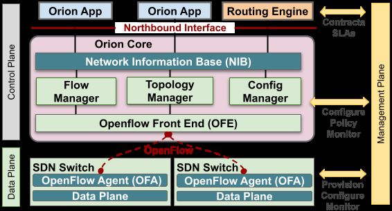
requirements of the NIB and the development model that al-         ing controllers incorporate (Kandoo [35] being an exception).
lows dozens of engineers to independently and simultaneously       Hierarchy enabled fabric-level drain sequencing 1 and optimal
develop, test, and deploy their services through well-defined,     WCMP-based (Weighted Cost Multi-Pathing) routing [36].
simple, but long-lived contractual APIs.                              We distribute Orion’s logic over multiple processes for
   While Orion has been a success at Google, neither our           scalability and fault-tolerance, a feature shared with other
design nor the SDN approach are panaceas. We describe four         production-oriented controllers such as ONOS [4] and Open-
key challenges we faced in Orion—some fundamental to SDN           Daylight [24], and originally proposed by Hyperflow [30].
and some resulting from our own design choices—along with          Unlike our previous design, Orion uses a single configuration
our approach to addressing them:                                   for all processes, applied atomically via the NIB, precluding
   #1: Logically centralized control require fundamentally         errors due to inconsistent intended state.
high performance for updates, in-memory representation                Orion uses database-like tables to centrally organize state
of state, and appropriate consistency levels among loosely-        produced and consumed by SDN programs, a feature shared
coordinating micro-service SDN applications.                       with a few other OpenFlow controllers such as ONOS [4],
   #2: The decoupling of control from hardware elements            Flowlog [27], and Ravel [32]. The combination of all of
breaks fate sharing in ways that make corner-case failure han-     these techniques – hierarchy, distribution, and database-like
dling more complex. In particular, control software failure        abstractions – allowed Orion to meet Google’s availability
does not always mean the corresponding hardware element            and performance requirements in the datacenter and WAN.
has failed. Consider the case where the control software runs         While Orion is an evolution in the development of Open-
in a separate physical failure domain connected through an         Flow controllers, its modular decomposition of network func-
independent out-of-band control network. Either the physical       tions (e.g., routing, flow programming, switch-level protocols,
infrastructure (control servers, their power or cooling) or con-   etc.) is a design goal shared with pre-OpenFlow systems such
trol network failure can now result in at least the perception     as 4D/Tesseract [33] and RCP [6]. Single-switch operating
of a sudden, massively correlated failure in the data plane.       systems that similarly employ microservices and a centralized
   #3: Managing the tension between centralization and fault       database architecture include Arista EOS [3] and SONiC [25].
isolation must be balanced carefully. At an extreme, one could
imagine a single logical controller for all of Google’s network
                                                                   3     Design Principles
infrastructure. At another extreme, one could consider a single    We next describe principles governing Orion’s design. We
controller for every physical switch in our network. While         established many of these during the early stages of building
both extremes can be discarded relatively easily, finding the      Orion, while we derived others from our experience operating
appropriate middle ground is important. On the one hand,           Orion-based networks. We group the principles into three
centralization is simpler to reason about, implement, and          categories: environmental – those that apply to production
optimize. On the other, a centralized design is harder to scale    networks, architectural – those related to SDN, and imple-
up vertically and exposes a larger failure domain.                 mentation – those that guide our software design.
   #4: In a global network setting, we must integrate existing     3.1      Principles of production networks
routing protocols, primarily BGP, into Orion to allow inter-
operation with non-SDN peer networks. The semantics of                Intent-based network management and control. Intent-
these protocols, including streaming updates and fate sharing      based networks specify management or design changes by
between control and data plane, are a poor match to our choice     describing the new intended end-state of the network (the
of SDN semantics requiring adaptation at a number of levels.       “what”) rather than prescribing the sequence of modifications
   This paper presents an introductory survey of Orion. We         to bring the network to that end-state (the “how”). Intent-
outline how we manage these concerns in its architecture,          based networking tends to be robust at scale, since high-level
implementation, and evolution. We also discuss our produc-         intent is usually stable over time, even when the low-level
tion experiences with running Orion, pointing to a number of       state of network elements fluctuates rapidly.
still open questions in SDN’s evolution. We will share more           For example, consider a situation where we wish to tem-
details and experiences in subsequent work.                        porarily “drain” (divert traffic away from) a cluster while we
                                                                   simultaneously add new network links to augment the ingress
2    Related Work                                                  and egress capacity of the cluster. As those new links turn
                                                                   up, the stable drain intent will also apply to them, causing the
Orion was designed with lessons learned from Onix [18].
                                                                   underlying networking control system to avoid using them.
Unlike Onix’s monolithic design with cooperative multi-
threading, Orion introduced a distributed design with each            In Orion, we use an intent-based approach for updating the
application in a separate process. While Onix introduced           network design, invoking operational changes, and adding
a NIB accessible only to applications in the same process,         new features to the SDN controller. For example, we capture
Orion’s is accessible by applications within and across do-            1 Fabric-level
                                                                                   drain sequencing refers to redirecting traffic in a loss-free
mains, providing a mechanism for hierarchy, which few exist-       manner, throughout the fabric, away from a target device being drained.

84   18th USENIX Symposium on Networked Systems Design and Implementation                                            USENIX Association
intended changes to the network’s topology in a model [26],
which in turn triggers our deployment systems and opera-
tional staff to make the necessary physical and configuration
changes to the network. As we will describe later, Orion
propagates this top-level intent into network control applica-
tions, such as routing, through configuration and dynamic
state changes. Applications react to top-level intent changes
Figure 1: Network behavior in three cases: Normal (left): A net-
by mutating their internal state and by generating intermedi-
work with healthy switches. Flows from top to bottom switches use
ate intent, which is in turn consumed by other applications. all middle switches. Fail Closed (mid): With few switches in un-
The overall system state evolves through a hierarchical prop- known state (grey), the controller conservatively routes around them.
agation of intent ultimately resulting in changes to the pro- Fail Static (right): With enough switches in unknown state, the
grammed flow state in network switches. controller no longer routes around newly perceived failed switches.
Align control plane and physical failure domains. One
potential challenge with decoupling control software from packet loss), (ii) unhealthy, when a switch declares itself to
physical elements is failure domains that are misaligned or too be unhealthy, when neighbouring switches report unhealthy
large. For misalignment, consider the case in which a single conditions or indirect signals implicate the switch, and (iii)
SDN controller manages network hardware across portions of unknown, with no recent control communication with a switch
two buildings. A failure in that controller can cause correlated and no indirect signals to implicate the switch.
failures across two buildings, making it harder to meet higher- A switch in the unknown state could be malfunctioning, or
level service SLOs. Similarly, the failure of a single SDN it could simply be unable to communicate with a controller
controller responsible for all network elements in a campus (a fairly common occurrence at scale). In comparison, the
would constitute too large a vulnerability even if it improved unhealthy state is fairly rare, as there are few opportunities to
efficiency due to a centralized view. diagnose unequivocal failure conditions in real time.2
We address these challenges by carefully aligning network The controller aggregates individual switch states into a
control domains with physical, storage, and compute domains. network-wide health state, which it uses to decide between
As one simple example, a single failure in network control a pessimistic or an optimistic reaction. We call these Fail
should not impact more than one physical, storage, or com- Closed and Fail Static, respectively. In Fail Closed, the con-
pute domain. To limit the “blast radius” of individual con- troller re-programs flows to route around a (perceived) failed
troller failures, we leverage hierarchical, partitioned control switch. In Fail Static, the controller decides not to react to a
with soft state progressing up the hierarchy (§5.1). We explic- switch in an unknown, potentially failed, state, keeping traffic
itly design and test the network to continue correct, though flowing toward it until the switch state changes or the network
likely degraded, operation in the face of controller failures. operator intervenes. Figure 1 illustrates an example of normal
operation, Fail Closed reaction, and Fail Static condition.
3.2 Principles related to an SDN controller In Fail Static, the controller holds back from reacting to
SDN enables novel approaches to handling failures, but avoid worsening the overall state of the network, both in
it also introduces new challenges requiring careful design. terms of connectivity and congestion. The trade-off between
The SDN controller is remote from the network switches, Fail Closed and Fail Static is governed by the cost/benefit
resulting in the lack of fate sharing but also the possibility of implication of reacting to the unknown state: if the element
not being able to communicate with the switches. in the unknown state can be avoided without a significant
Lack of fate sharing can often be used to our advantage. performance cost, the controller conservatively reacts to this
For example, the network continues forwarding based on state and triggers coordinated actions to steer traffic away
its existing state when the controller fails. Conversely, the from the possible failures. If the reaction would result in a
controller can repair paths accurately and in a timely manner significant loss in capacity or loss in end-to-end connectivity,
when individual switches fail, by rerouting around them. the controller instead enters Fail Static mode for that switch.
React optimistically to correlated unreachability. The In practice we use a simple “capacity degradation threshold”
loss of communication between controller and switches poses to move from Fail Closed to Fail Static. The actual threshold
a difficult design challenge as the controller must deal with value is directly related to: (1) the operating parameters of
incomplete information. We handle incomplete information the network, especially the capacity headroom we typically
by first deciding whether we are dealing with a minor failure reserve, for example, to support planned maintenance; (2) the
or a major one, and then reacting pessimistically to the former level of redundancy we design in the topology and control
and optimistically to the latter.
2 It is not common for a software component to be able to self-diagnose a
We start by associating a ternary health state with network failure, without being able to avoid it in the first place, or at least repair it.
elements: (i) healthy with a recent control communication (a Slightly more common is the ability to observe a failure from an external
switch reports healthy link and programming state with no vantage point, e.g. a neighboring switch detecting a link “going down.”
USENIX Association 18th USENIX Symposium on Networked Systems Design and Implementation 85domains. We aim to preserve a certain amount of redundancy decoupled components. At the same time, these components
even in the face of capacity degradation. had to interact with one another to realize a tightly-coupled
In our experience, occurrences of Fail Static are fairly com- control system reflecting the structure and dynamics of net-
mon and almost always appropriate, in the sense that they are work control. We achieved this goal through:
not associated with loss of data plane performance. Often Fail • a microservice architecture with separate processes rather
Static is triggered by failures in the control plane connectivity than a monolithic block which we adopted in our first
between the SDN controller and the network elements, or by generation SDN controller [18], for software evolvability
software failures in the controller. Neither of these directly and fault isolation.
affect the data plane health. • a central pub-sub system (NIB) for all the communication
We view the ability to Fail Static as an advantage of SDN between microservices, which took care of the tightly-
systems over traditional distributed-protocol systems. Dis- coupled interaction across processes.
tributed systems are also subject to some of the failures that Failure domain containment (§3.1) imposes an upper limit
could benefit from a Fail Static response. However, they are to the size of control domains. Nevertheless, we were con-
not easily amenable to realize a Fail Static behavior because cerned with the performance, scalability, and fault model of a
they only have a local view. It is far easier for a centralized single NIB to coordinate all communication and state within
controller to assess if it should enter Fail Static when it can a control domain. We satisfied our performance concerns
observe correlated network failures across its entire domain. through benchmarking efforts, and fault tolerance concerns
Exploit both out-of-band and in-band control plane by limiting control domain scope and the ability to fail static,
connectivity. In a software-defined network, a key consid- including between control domains.
eration is connectivity between the “off box” controller and Based on years of experience, the NIB has been one of
the data plane switches. We must solve the bootstrap prob- our most successful design elements. It manages all inter-
lem of requiring a functioning network to establish baseline component communications, allows us to create a “single
control. Options include using: i) the very network being con- arrow of time,” establishing an order among the otherwise
trolled (“in-band”) or ii) a (physically or logically) separate concurrent events across processes. This brought significantly
“out-of-band” network. While a seemingly simple question, useful side effects including much improved debuggability of
considerations regarding pure off-box SDN control, circu- the overall system. It also allows us to store event sequences
lar dependencies between the control and dataplane network, (NIB traces) in external systems and use them for offline
ease of debuggability, availability, manageability and cost of troubleshooting and independent validation of subsystems,
ownership make this topic surprisingly complex. which we use in component-level regression testing.
The simplest approach is to have a physically separate out- Next, we discuss the principles of intent based control,
of-band control/management plane network (CPN) for com- introduced in 3.1, reconciliation of state as well as the impli-
munication between controller and switches orthogonal to cations of various failure modes in an SDN-based system:
the dataplane network. This approach cleanly avoids circular Intent flows from top to bottom. The top level intent for
dependencies, keeping the control model simple and enabling the system as a whole is the operator intent and the static con-
easy recovery from bugs and misconfiguration. Ideally, we figuration. As intent propagates through the system via NIB
would like the out-of-band control network to be highly avail- messages, it triggers local reactions in subsystems that gen-
able, easy to manage and maintain, and cost effective. In erate intermediate intent consumable by other sub-systems.
the end, a separate CPN means installing and operating two Higher-level intent is authoritative and any intermediate in-
distinct networks with different operational models and inde- tent (also known as derived state) is rebuilt from it. The
pendent failure characteristics. While failure independence programmed switch state is the ground truth corresponding
is often a desirable property, subtle or rare failure scenarios to the intent programmed into dataplane devices.
mean the entire data plane could go down if either the data- The authoritative intent must always be reflected in the
plane or control plane fails. We describe our choice of hybrid ground truth. The controller ensures that any mismatch is
CPN for Orion in §5. corrected by migrating the ground truth toward the intended
state in a way that is minimally disruptive to existing data
3.3 Software design principles plane traffic. We refer to this process as “state reconciliation”.
Enabling a large-scale software development environment Reconciliation is best performed in the controller
was a key motivation for building our own SDN controller. which has a global view since minimal disruption often re-
Critical to the success of SDN is the ability to safely deploy quires coordination across switches such that changes are
new functionality across the network incrementally with fre- sequenced in a graceful and loop-free manner. Reconciliation
quent software releases. This, in turn, means that a substantial is a powerful concept that allows reasoning about complex
team of engineers must be able to develop multiple indepen- failure modes such as Orion process restarts as well as lack
dent features concurrently. The need to scale engineering of fate sharing between the data and control planes.
processes led to a modular system with a large number of Availability of high level intent is crucial to keep the top-
86 18th USENIX Symposium on Networked Systems Design and Implementation USENIX AssociationOf note, durability [14] was not a requirement for the NIB be-
cause its state could be reconstructed from network switches
and other sources in the event of a catastrophic failure.
NIB Entities. The NIB consists of a set of NIB entity tables
where each entity describes some information of interest to
other applications or observers both local or external to the
domain. Some of the entity types include:
• Configured network topology. These capture the config-
ured identities and graph relationship between various net-
work topological elements. Examples include Port, Link,
Figure 2: Overview of Orion SDN architecture and core apps. Interface, and Node tables.
• Network run-time state. This could be topological state,
down intent-based system simple. To achieve this goal we
forwarding state (e.g. ProgrammedFlow table), pro-
minimize the time when the intent is temporarily unavailable
tocol state (e.g. LLDPPeerPort table), statistics (e.g.
(e.g., because of process restarts or communication failure
PortStatistics table).
between components).
• Orion App Configuration. Each app’s configuration is
4 Architecture captured as one or more NIB tables, e.g. LLDPConfig.
Figure 2 depicts the high-level architecture of Orion, and how Protocol Buffer Schema. We represent the schema for
it maps to the textbook ONF view [7]. For scalability and each NIB entity as a protocol buffer message [8]. Each row
fault isolation, we partition the network into domains, where in that NIB entity table is an instantiation of this schema. The
each domain is an instance of an Orion SDN controller. first field of each entity schema is required to be a NIBHeader
message which serves as the key for that entity. The NIB does
The data plane consists of SDN switches at the bottom.
not enforce referential integrity for foreign keys; however,
Orion uses OpenFlow [23] as the Control to Data Plane In-
inconsistencies fail an internal health-check.
terface (CDPI). Each switch runs an OpenFlow Agent (OFA)
for programmatic control of forwarding tables, statistics gath- An example entity represented in the NIB is a Link entity.
ering, and event notification. The control plane consists of A link is modelled as foreign key references to Port and Node
Orion Core in the center and SDN applications at the top. entities respectively. This expresses the connection between
The control plane is physically separate from the data plane two ports of two switches. Additionally, a status (up, down,
and logically centralized, providing a global view of the do- or unknown), is modelled as part of the Link entity. The full
main. Though logically centralized, the Orion Core controls protocol buffer is shown in the appendix.
the network through distributed controller processes. The Protocol buffers allow us to reuse well-understood patterns
NIB provides a uniform SDN NorthBound Interface for these for schema migrations. For example, adding a new field to
applications to share state and communicate requirements. a table has built-in support for backward and forward com-
The Orion Core is responsible for (i) translating these re- patibility during an upgrade despite some applications still
quirements into OpenFlow primitives to reconcile switches’ running with the previous schema.
programmed state with intended state and (ii) providing a NIB API. The NIB provides a simple RPC API (Read,
view of the runtime state of the network (forwarding rules, Write, Subscribe) to operate on NIB tables. The Write opera-
statistics, data plane events) to applications. tion is atomic and supports batching. The Subscribe operation
supports basic filtering to express entities of interest. The NIB
4.1 Orion Core notification model provides sequential consistency of event
The NIB is the intent store for all Orion applications. It ordering. It also supports coalescing multiple updates into a
is implemented as a centralized, in-memory datastore with single notification for scale and efficiency reasons.
replicas that reconstruct the state from ground-truth on failure. The Config Manager provides an external management
The NIB is coupled with a publish-subscribe mechanism to API to configure all components in an Orion domain. The
share state among Orion applications. The same infrastructure domain configuration is the set of app configurations running
is used externally to collect all changes in the NIB to facilitate in that domain. For uniformity and ease of sharing, an app
debugging. The NIB must meet the following requirements: config consists of one or more NIB tables. To ensure a new
• Low External Dependency. As Orion programs the net- configuration is valid, it is first validated by the running in-
work supporting all higher-level compute and storage ser- stance. The semantics of pushing config need to be atomic, i.e.
vices, it cannot itself depend on higher-level services. if one or more parts of the overall config fail validation, the
• Sequential Consistency of Event Ordering. To simplify overall config push must fail without any side effects. Since
coordination among apps, all apps must see events in the Orion apps that validate various parts of the config run de-
same order (arrow of time [20]). coupled, we employ a two-phase commit protocol to update
USENIX Association 18th USENIX Symposium on Networked Systems Design and Implementation 87the NIB: The config is first staged in shadow NIB tables, and computing the next available shortest path when the current
each app verifies its config. Upon success, we commit the set of nexthops for a prefix becomes unreachable. For im-
shadow tables to live tables atomically. proved capacity, RE performs load balancing within a domain
The Topology Manager sets and reports the runtime state by spreading traffic across multiple viable paths, and through
of network dataplane topology (node, port, link, interface, non-shortest-path forwarding, as requested by client apps. RE
etc.). It learns the intended topology from its config in the also manages the associated switch hardware resources (e.g.
NIB. By subscribing to events from the switches, it writes the Layer-3 tables) among its client routing apps.
current topology to tables in the NIB. The Topology Manager A key highlight of Orion Routing Engine is the ability
also periodically queries port statistics from the switches. to do loss-free sequencing from the currently programmed
The Flow Manager performs flow state reconciliation, en- pathing solution to a new pathing solution. This may happen
suring forwarding state in switches matches intended state in reaction to changes in network states (e.g. a link being
computed by Orion apps and reflected in the NIB. Recon- avoided). In a legacy network, the eventually consistent nature
ciliation occurs when intent changes or every 30 seconds by of updates from distributed routing protocols (e.g. BGP) can
comparing switch state. The latter primarily provides Orion result in transient loops and blackholes in the data plane.
with switch statistics and corrects out-of-sync state in the rare In contrast, RE exploits its global view to sequence flow
case that reconciliation on intent change failed. programming: before programming a flow that steers traffic to
The OFE (Openflow FrontEnd) multiplexes connections a set of switches, RE ensures the corresponding prefixes have
to each switch in an Orion domain. The OpenFlow protocol been programmed on those nexthop switches. Analogous
provides programmatic APIs for (i) capabilities advertise- checks are done before removing a flow.
ment, (ii) forwarding operations, (iii) packet IO, (iv) teleme- Figure 3 walks through an end-to-end route programming
try/statistics, and (v) dataplane event notifications (e.g. link example. As evident from the sequence of operations, the NIB
down) [23]. These are exposed to the Topology and Flow semantics lend themselves to an asynchronous intent-based
Manager components via OFE’s northbound RPC interface. programming model (as opposed to a strict request-response
Packet-I/O. Orion supports apps that send or receive con- interaction). A common design pattern is to use a pair of
trol messages to/from the data plane through OpenFlow’s NIB tables, where one expresses the intent from the producer,
Packet-I/O API: a Packet-Out message sends a packet while the other captures the result from the consumer. Both
through a given port on the switch, while a Packet-In no- intent and result tables are versioned. An app can change
tification delivers a data plane packet punted by the switch to the intent many times without waiting for the result, and the
the control plane. The notification includes metadata such as result table is updated asynchronously.
the packet’s ingress port. Orion apps can program punt flows
4.3 Orion Application Framework
and specify filters to receive packets of interest.
Orion Core apps are network-type agnostic by design. No The Orion Application Framework is the foundation for
“policy” is baked into them; it belongs to higher-level SDN every Orion application.The framework ensures developers
applications instead. Core apps program, and faithfully reflect, use the same patterns to write applications so knowledge of
the state of the data plane in the NIB in a generic manner. one SDN application’s control-flow translates to all applica-
tions. Furthermore, the framework provides basic functional-
4.2 Routing Engine ity (e.g. leader-election, NIB-connectivity, health-monitoring)
Routing Engine (RE) is Orion’s intra-domain routing con- required by all applications in all deployments.
troller app, providing common routing mechanisms, such as High Availability. Availability is a fundamental feature for
L3 multi-path forwarding, load balancing, encapsulation, etc. networks and thereby SDN controllers. Orion apps run as
RE provides abstracted topology and reachability infor- separate binaries distributed across network control server ma-
mation to client routing applications (e.g. an inter-domain chines. This ensures applications are isolated from bugs (e.g.,
routing app or a BGP speaker app). It models a configured memory corruption that leads to a crash) in other applications.
collection of switches within an Orion domain as an abstract Beyond isolation, replicating each application on three
routing node called a supernode [13] or middleblock [28]. different physical machines ensures fault tolerance for both
Client routing applications provide route advertisements at planned (e.g. maintenance) as well as unplanned (e.g. power
supernode granularity, specifying nexthops for each route in failures) outages. The application framework facilitates repli-
terms of aggregate or singleton external ports. cation by providing an abstraction on top of leader election
RE disaggregates the route advertisements from its clients as well as life-cycle callbacks into the application.
into individual node-level reachability over respective exter- An application goes through a life-cycle of being activated,
nal ports and computes SPF (Shortest Path First) paths for receiving intent/state updates from the NIB, and then being
each prefix. RE avoids paths that traverse drained, down or deactivated. Identifying/arbitrating leadership and its transi-
potentially miscabled links.3 It also reacts to local failure by tion (referred to as failover) among replicas is abstracted and
3A link is considered miscabled when a port ID learned by a neighbor node via LLDP and reported to Orion does not match the configured port ID.
88 18th USENIX Symposium on Networked Systems Design and Implementation USENIX AssociationFigure 3: Intent-based route programming on abstracted domain topology: (a) Routing Engine learns external prefix 1.2.3.0/24 over trk-1, and
programs nodes to establish reachability. (b) Example of end-to-end route programming. The Routing App provides a high-level RouteAdvert
on supernode-1 via the NIB. Routing Engine translates the RouteAdvert to a low-level Flow update on node i and sends to Flow Manager.
Acknowledgements follow the reverse direction to the Routing App. Similar route programming applies to all domain nodes.
thereby hidden from the application author, reducing surface Flow Manager begins reconciling NIB state to the physical
area for bugs as well as complexity. switches. This prevents unintentional erasure of flow state
Capability Readiness Protocol. One of the challenges we from switches, which would lead to traffic loss. As Figure 4
faced previously was an orderly resumption of operation after shows, the required and provided data that each application
controller failover. In particular, when a controller’s NIB fails, specifies creates a directed acyclic graph of capabilities de-
the state of the new NIB needs to be made consistent with the pended upon and provided, and thus the complete NIB state
runtime state of the network, as well as the functional state is reconciled consistently after any restart. Apps can have
of all apps and remote controllers. In an extreme case, an mutual dependency on different capabilities as long as they
Orion requirement is to be able to, without traffic loss, recover do not form a loop. A healthy Orion domain completes the
from a complete loss/restart of the control plane. To support full capability graph quickly on reconciliation, a condition we
this, the Orion architecture provides a Capability Readiness check in testing and alert on in production. Since this graph
Protocol. With this protocol, applications have a uniform way is static, such testing prevents introducing dependency loops.
of specifying which data they require to resume operation, In the event of a total loss of state, Config Manager re-
and which data they provide for other applications. trieves the static topology from Chubby [5], an external,
A capability is an abstraction of NIB state, each can be highly-available service for locking and small file storage.
provided and consumed by multiple apps. Capability-based It then provides a CONFIG_SYNC capability to unblock Topol-
coordination keeps the Orion apps from becoming “coupled”, ogy Manager and Flow Manager. The two connect to switches
in which a specific implementation of one app relies on imple- specified in the config and read switch states and programmed
mentation details or deployment configuration of another app. flows. Then, ARP and Routing Engine can be unblocked to
Such dependencies are a problem for iteration and release ve- generate intended flows that need to be programmed; they
locity. For example, multiple apps can provide the capability also provide their own FLOWS_DESIRED capability to Flow
of “producing flows to program”, and the Flow Manager can Manager, which proceeds to program the switches.
be oblivious to which ones are present in the domain. Apps that retrieve their state from a remote service must
explicitly manage and support the case in which the service
is unavailable or disconnected to prevent prolonged domain
reconciliation delays. Cached data is typically used until the
authoritative source of the inputs can be reached.
5 Orion-based Systems
Among the many design choices when implementing Orion
to control a specific network, three prominent ones include
the mapping of network elements to controllers, the method
of controller to switch communication, and connectivity to ex-
Figure 4: Capability Readiness graph for flow programming. ternal networks running standard routing protocols. We first
review these common choices across two Google network ar-
The Capability Readiness protocol requires, after a NIB chitectures, Jupiter and B4, and then describe specific details
failover, that all apps report readiness of their flows before for each architecture. Less relevant in a networking context,
USENIX Association 18th USENIX Symposium on Networked Systems Design and Implementation 89details of the NIB implementation are in the appendix. been a key design to reduce vulnerability to CPN failures.
Furthermore, we introduced in-band backup control of
Control domains. The choice of elements to control in an
devices connected to the CPN for additional robustness.
Orion domain involves multiple tradeoffs. Larger domains
yield optimal traffic distributions and loss-free route sequenc- External connectivity. We use BGP at the border of data-
ing for more intent changes, at the price of increased blast center networks to exchange routes with Google’s wide-area
radius from any failure. In Jupiter, we use a hierarchy of par- networks: B2 (which also connects to the Internet) and B4.
titioned Orion domains; in B4, a flat partitioning of Orion do- These routes include machine addresses and also unicast and
mains communicating with non-Orion global services. Each anycast IPs for Google services. BGP attributes such as com-
came with challenges in production, which we review in §7. munities, metrics, and AS path propagate state throughout
Google’s networks. In addition to reachability, this can in-
Control channel. As discussed in §3.1, we faced tradeoffs clude drain state, IPv6-readiness, and bandwidth for WCMP.
when designing the Control Plane Network (CPN) connecting The use of BGP is a necessity for eventual route propaga-
Orion controllers to the data plane. The cost and complexity tion to the Internet, but a design choice internally. The choice
of a second network led us to a hybrid design where only the was made to simplify inter-connection with traditional, non-
Top-of-Rack (ToR) switches were controlled in-band. SDN routers as well as previous SDN software [18]. BGP also
• Separation of control and data plane: When we embarked brings operator familiarity when defining polices to specify
on building B4 and Jupiter, we embraced the SDN philoso- path preferences during topological changes.
phy in its purest form: software-defined control of the net- An Orion app, Raven [34], integrates BGP and IS-IS into
work based on a logically centralized view of the network Orion. Raven exchanges messages with peers via Orion’s
state outside the forwarding devices. To this end, we did Packet-I/O. Raven combines these updates with local routes
not run any routing protocols on the switches. For the con- from the NIB into a standard BGP RIB (Route Information
trol plane, we ran a separate physical network connected to Base). Routes selected by traditional Best-Path Selection are
the switches’ management ports. We ran conventional on- then sent, depending on policy, to peer speakers as BGP mes-
box distributed routing protocols on the CPN. Compared sages, as well as the local NIB in the form of RouteAdvert
to the data plane network, the CPN has smaller bandwidth updates. To reduce complexity, Raven’s associated BGP
requirements, though it required N+1 redundancy. “router” is the abstract supernode provided by RE (§4.2).
• CPN scale and cost: Typical Clos-based data center net- Unfortunately, BGP is somewhat mismatched with our
works are non-oversubscribed in the aggregation layers design principles: it uses streaming rather than full intent
[28] with oversubscription of ToR uplinks based on the updates, its local view precludes a threshold-based fail static
bandwidth requirements of compute and storage in the policy and global rebalancing during partial failures, and it
rack. A Clos network built with identical switches in each ties control-plane liveness to data-plane liveness. In our pro-
of its N stages will have the same number of switches duction experience, we have had both kinds of uncorrelated
(say, K) in all but two stages. The topmost stage will have failures, which, as in non-SDN networks, become correlated
K/2 switches since all ports are connected to the previ- and cause a significant outage only due to BGP. By contrast,
ous stage. The ToR stage will have SK switches, where Orion’s fail static policies explicitly consider control-plane
S is the average oversubscription of uplinks compared to and data-plane failure as independent. Adding fail static be-
downlinks. Thus, the number of ToR switches as a frac- havior to these adjacencies is an area of ongoing development.
tion of the total is 2S/(2S + 2N − 3). In a Clos network
with N = 5 stages and an average ToR oversubscription, S, 5.1 Jupiter
ranging from 2-4, ToR switches account for 36% to 53% We initially developed Jupiter [28], Google’s datacenter
of the total. Thus, not requiring CPN connectivity to them network, with our first generation SDN-based control system,
substantially reduces CPN scale and cost. Onix [18]. The Orion-based solution presented here is a
• CPN cable management: Managing ToRs inband removes second iteration based on lessons from the Onix deployment.
the burden of deploying individual CPN cables to each The Jupiter datacenter network consists of three kinds of
rack spot in the datacenter. building blocks, each internally composed of switches form-
• Software complexity of inband ToRs: Since ToRs are the ing a Clos-network topology: (i) aggregation blocks [28]
leaf switches in a Clos topology, their inband management connected to a set of hosts, (ii) FBRs (Fabric Border Routers,
does not require on-box routing protocols. We designed also called Cluster Border Routers in [28]) connected to the
simple in-band management logic in the switch stack to set WAN/Campus network, and (iii) spine blocks that intercon-
the return path to the controller via the ToR uplink from nect aggregation blocks and FBRs.
which the ToR’s CPU last heard from the controller. We organize Orion domains for Jupiter hierarchically as
• Availability and debuggability considerations: Over the shown in Figure 5. First, we map physical Orion domains to
years, we have hardened both the CPN and the inband- the Jupiter building blocks. Each physical domain programs
controlled ToR to improve availability. “Fail static” has switches within that domain. Aggregation block domains es-
90 18th USENIX Symposium on Networked Systems Design and Implementation USENIX AssociationFigure 5: Jupiter topology overlaid with Orion domains partitioned Figure 6: Jupiter fabric-level IBR-C control flow of one color. by color. Colored links and spine domains are controlled by the respectively colored IBR-C. Uncolored aggregation block/FBR domain-level component, merges routes from different IBR-C domains are controlled by all IBR-Cs. Only control sessions and colors into RouteAdvert updates. Finally, Routing Engine data links of the red color are displayed. and Orion Core program flows as shown in Figure 3. tablish connectivity among hosts attached to it. FBR domains Convergence. We care about two types of convergence in use Raven to maintain BGP sessions with fabric-external Jupiter: data plane convergence and control plane conver- peers. Multiple spine blocks can map to a single Orion do- gence. Data plane convergence ensures there are valid paths main, but each domain must contain fewer than 25% of all among all source/destination pairs (no blackholing) while spine blocks to limit the blast radius of domain failure. control plane convergence restores (near) optimal paths and Second-level Orion domains host a partitioned and central- weights in the fabric. Workflows that require changes to the ized routing controller IBR-C (Inter-Block Routing Central). network use control plane convergence as a signal they can Operating over Routing Engine’s abstract topology, IBR-C proceed safely. Convergence time is the duration between a aggregates network states across physical domains, computes triggering event and all work complete in data/control plane. fabric-wide routes, and programs physical domains to estab- Jupiter’s reaction to link/node failures is threefold. First, lish fabric-wide reachability. While these virtual domains upon detection of link-layer disruption, switches adjacent start from the same foundations, they do not contain some to the failed entity perform local port pruning on the output Orion core apps for controlling devices directly. group. However, this is not possible if no alternative port To avoid a single point of failure, we partitioned (or exists or peer failure is undetectable (e.g., switch memory sharded) IBR-C into four planes called “colors,” each control- corruption). Second, RE programs the domain to avoid this ling 25% of the spine blocks and hence a quarter of paths be- entity. This is similar to switch port pruning, but could happen tween each pair of spine blocks and aggregation blocks/FBRs. on non-adjacent switches within the domain. For failures that Therefore, the blast radius of a single controller does not do not affect inter-block routing, the chain of reaction ends exceed 25% of the fabric capacity. Sharding centralized here. Otherwise, in a third step, RE notifies IBR-C of the controllers avoids failures where a single configuration or failure, as shown in Figure 6. When fabric-wide programming software upgrade affects the whole fabric. Additional protec- is complete, IBR-C signals the control plane has converged. tion was added to stage configuration changes and upgrades This multi-tier reaction is advantageous for operations, as it to avoid simultaneous updates across colors. While sharding minimizes data plane convergence time and thus traffic loss. provided higher resiliency to failures, the trade-off was an Since a single entity failure can lead to successive events increased complexity in merging routing updates across col- in different domains (e.g., spine switch failure causing aggre- ors in aggregation block and FBR domains, as well as a loss gation block links to fail), it could trigger multiple IBR-C and in routing optimality in case of asymmetric failures across domain programming iterations to reach final convergence. colors. We have considered even deeper sharding by splitting Many independent events also happen simultaneously and get aggregation blocks into separate domains, each controlling a processed by Orion together, which can further delay con- portion of the switches. This option was rejected due to even vergence. Hence, we will evaluate Orion’s performance in higher complexity while marginally improving availability. example convergence scenarios in §6. Figure 6 illustrates the fabric-level control flow of one Implementation Challenges. One challenge with the orig- IBR-C color. IBR-C subscribes to NIBs in all aggregation inal Jupiter implementation [28] was optimally distributing block/FBR domains and spine domains of the same color traffic across multiple paths. Capacity across paths can differ for state updates. After aggregation at Change Manager, the due to link failures and topology asymmetry (e.g., different Solver computes inter-block routes and Operation Sequencer link count between a spine-aggregation block pair). In order writes the next intended routing state into NIB tables of corre- to optimally allocate traffic, Jupiter/Orion employs WCMP sponding domains. IBR-D (Inter-Block Routing Domain), a to vary weights for each path and nexthop. Due to the precise USENIX Association 18th USENIX Symposium on Networked Systems Design and Implementation 91
tunnel set or BGP/ISIS routes.
                                                                       The Path Exporter subscribes to multiple NIB tables and
                                                                    exports the observed dataplane state to the global services. It
                                                                    reports the dataplane state at the supernode level, including
                                                                    the abstract topology (e.g., supernode-supernode link capac-
                                                                    ities), the abstract forwarding table (TE tunnels and BGP
                                                                    routes), and the abstract port statistics.
                                                                       The Central TE Server [13,15] is a global traffic engineer-
                                                                    ing service which optimizes B4 paths using the TE protocol
                                                                    offered by the TE App in each domain. The Bandwidth En-
                 Figure 7: B4 Control Diagram                       forcer [19] is Google’s global bandwidth allocation service
                                                                    which provides bandwidth isolation between competing ser-
weight computation for each forwarding entry, weights need          vices via host rate limiting. For scalability, both the Central
to be adjusted across the entire fabric to fully balance traffic.   TE Server and Bandwidth Enforcer use the abstract network
Another challenge was transient loops or blackholes during          state provided by the Path Exporter.
route changes. This is due to asynchronous flow program-
ming in traditional routing protocols and in our previous SDN       6    Evaluation
controller [18]. With Orion-based Jupiter, we implement             We present microbenchmarks of the Orion NIB, followed
end-to-end flow sequencing in both IBR-C and RE.                    by Jupiter evaluation using production monitoring traces col-
   At the scale of Jupiter, network events arrive at IBR-C at       lected since January 2018. Orion also improved B4 perfor-
a high frequency, which sometimes surpasses its processing          mance, as published previously [13].
speed. To avoid queue buildup, IBR-C prioritizes processing
certain loss-inducing events (e.g., link down) over noncritical     NIB performance. To characterize NIB performance, we
events (e.g., drain). Upon an influx of events, IBR-C only pre-     show results of a microbenchmark measuring the NIB’s
empts its pipeline for loss-inducing events. It reorders/queues     read/write throughput while varying the number of updates
other events for batch processing upon the completion of            per batch. A batch is a set of write operations composed
higher priority processing. This is a trade-off to minimize         by an app that updates rows of different NIB tables atom-
traffic loss while avoiding starvation of lower priority events.    ically. In Figure 8, we observe throughput increase as the
§6 quantifies the benefits of this approach in more detail.         batch size becomes larger. At 50K updates per batch, the
                                                                    NIB achieves 1.16 million updates/sec in read throughput and
5.2    B4                                                           809K updates/sec in write throughput.
   Onix [18], the first-generation SDN controller for B4, ran          Write throughput at 500 updates per batch sees a de-
control applications using cooperative multithreading. Onix         cline. This reveals an implementation choice where the NIB
had a tightly-coupled architecture, in which control apps share     switches from single-threaded write to multi-threaded write
fate and a common threading pool. With Onix’s architecture,         if the batch size is greater than 500. When the batch size is
it was increasingly challenging to meet B4’s availability and       not large enough, up-front partitioning to enable parallelism
scale requirements; both have grown by 100x over a five year        is more expensive than the performance improvement. This
period [13]. Orion solved B4’s availability and scale problems      fixed threshold achieves peak performance on sampled pro-
via a distributed architecture in which B4’s control logic is       duction test data and performs well in production overall.
decoupled into micro-services with separate processes.              It could be removed in favor of a more dynamic adaption
                                                                    strategy to smooth the throughput curve.
   Figure 7 shows an overview of the B4 control architecture.
Each Orion domain manages a B4 supernode, which is a 2-             Data and control plane convergence. One key Jupiter per-
stage folded-Clos network where the lower stage switches are        formance characteristic is convergence time (§5.1). We mea-
external facing (see details in [13]). In B4, Routing Engine        sure convergence times in several fabrics, ranging from 1/16-
sends ingress traffic to all viable switches in the upper stage     size Jupiter to full-size Jupiter (full-size means 64 aggregation
using a link aggregation group (LAG), and uses two-layer            blocks [28]). Figure 9 captures data and control plane con-
WCMP to load-balance traffic toward the nexthop supernode.          vergence times of three types of common daily events in our
   The TE App is a traffic engineering agent for B4. It es-         fleet. The measurements are observed by Orion; switch-local
tablishes a session with global TE server instances to syn-         port pruning is an independent decision that completes within
chronize the tunnel forwarding state. It learns TE tunneling        a few milliseconds without Orion involvement.
ops from the primary TE server, and programs the ops via               In node/link down scenarios, the data plane converges
the RouteAdvert table. In addition, TE App also supports            within a fraction of a second. Both data and control plane
Fast ReRoute (FRR), which restores connectivity for broken          convergence times become longer as the fabric scales up by
tunnels by temporarily re-steering the traffic to the backup        16x. This is mainly because a larger number of aggregation

92    18th USENIX Symposium on Networked Systems Design and Implementation                                    USENIX Association
Figure 8: NIB throughput. Figure 9: Jupiter data/control plane convergence time in response to various network events.
Controller footprint: CPU and memory. Orion controller
jobs run on dedicated network control servers connected to the
CPN. This pool is comprised of regular server-class platforms.
We measure CPU and memory usage of each controller job
(including all three replicas) and group them by domain. Fig-
ure 11 shows that even in a full-size Jupiter, Orion domains
use no more than 23 CPU cores and 24 GiB of memory.
Figure 10: Time series of full fabric control plane convergence
on three large Jupiter fabrics. Y-axis is normalized to the base- 7 Production Experience
line convergence time in January 2018. Orion releases with major We briefly review some challenging experiences with Orion
performance improvements are highlighted by markers. when adhering to our production principles of limited blast-
radius and fail-static safety, and some more positive experi-
ences from following our software design principles.
7.1 Reliability and robustness
Failure to enforce blast radius containment. As de-
scribed in §5.1, the inter-block routing domain is global but
sharded into four colors to limit the blast radius to 25%. A
buggy IBR-C configuration upgrade caused a domain to re-
voke all forwarding rules from the switches in that domain
resulting in 25% capacity loss. Since high-priority traffic
Figure 11: Orion CPU/RAM usage in Jupiter domains. demand was below 25% of the fabric’s total capacity, only
after all four domains’ configurations were pushed did the
blocks and spine blocks require more affected paths to be workflow flag (complete) high-priority packet loss in the fab-
re-computed and re-programmed. Data plane convergence is ric. To prevent such a “slow wreck” and enforce blast radius
35-43x faster than control plane convergence, which effec- containment, subsequent progressive updates proceeded only
tively keeps traffic loss at a minimum. after confirming the previous domain’s rollout was successful,
Jupiter’s reaction to link drains is slightly different from and not simply the absence of high-priority packet loss.
failure handling. Drains are lossless, and do not include an Failure to align blast radius domains. A significant Orion
initial sub-optimal data plane reaction to divert traffic. Instead, outage occurred in 2019 due to misalignment of job-control
Orion only shifts traffic after computing a new optimal routing and network-control failure domains. Like many services at
state. Therefore, data and control plane convergence are Google, these Orion jobs were running in Borg cells [31]. Al-
considered equal. Overall, control plane convergence time though the Orion jobs were themselves topologically-scoped
for link drain is on par with node/link down scenarios. to reduce blast radius (§3.1), their assignment to Borg cells
We have continuously evolved Orion to improve Jupiter was not. As described in the incident report [9], when a fa-
scalability and workflow velocity. Key to this were enhance- cility maintenance event triggered a series of misconfigured
ments in IBR-C such as prioritized handling of select updates, behaviors that disabled Orion in those Borg cells, the result-
batch processing/reordering, and a conditionally preemptive ing failure was significantly larger than Google’s networks
control pipeline. Figure 10 shows the trend of three large had been previously designed to withstand. This outage high-
fabrics from January 2018 to April 2020; the control plane lighted the need for all management activities (job control,
convergence time in January 2018 was before these improve- configuration update, OS maintenance, etc.) to be scoped and
ments. Deployed over three major releases, each contributing rate-limited in a coordinated manner to fully realize the prin-
an average 2-4x reduction, the new processing pipeline (§5.1) ciple of blast-radius reduction. In addition, it highlighted a
delivered a 10-40x reduction in convergence time. gap in our fail-static implementation with regards to BGP.
USENIX Association 18th USENIX Symposium on Networked Systems Design and Implementation 93You can also read