Helios Tube Cleaning System Application Engineering Guide
←
→
Page content transcription
If your browser does not render page correctly, please read the page content below
Helios Tube Cleaning System®
Application Engineering Guide

Revision 0 02/07/2022

Helios Tube Cleaning System® – Application Engineering Guide

                                              Table of Contents
 INTRODUCTION ................................................................................................................................................

 APPLICATIONS .................................................................................................................................................

 FEATURE BENEFITS ...................................................................................................................................... 5

 NOMENCLATURE ........................................................................................................................................... 7

 EQUIPMENT OVERVIEW ............................................................................................................................... 8

 ACCESSORIES AND OPTIONS ..................................................................................................................... 9

 APPLICATIONS AND CONSIDERATIONS ................................................................................................ 10

 TECHNICAL DATA ....................................................................................................................................... 13

 EXAMPLE DRAWINGS AND TECHNICAL RESOURCES........................................................................ 21

 GUIDE SPECIFICATION .............................................................................................................................. 25

                                                                             2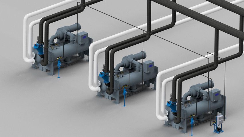
Helios Tube Cleaning System® – Application Engineering Guide

INTRODUCTION
The Helios Tube Cleaning System® provides continuous, in-situ, preventative tube cleaning of
up to five (5) heat exchangers.

Helios Tube Cleaning System Process Description
The Helios tube cleaning system includes multiple sub-components, including:

           Helios Skid
           Collectors (Qty. 1-5)
           Ball Traps (Qty. 1-5)

The Helios Skid is shared between the Collectors. Ball Traps are installed in the heat exchanger
piping at the outlet of each heat exchanger.

The Helios Controller will periodically inject and collect the cleaning balls to the heat
exchangers in series, using the pre-programmed timers and settings in the Helios Controller.

                                               3
Helios Tube Cleaning System® – Application Engineering Guide

APPLICATIONS
The Helios Tube Cleaning System® (Helios) is applicable to any shell and tube heat exchanger
with sufficient tube-side water flow. Minimum flow requirements vary based on the size and
type of heat exchanger tube, with a general minimum tube flow velocity requirement of 4 ft/s.
Consult your Innovas sales representative for details or specific application questions.

Common applications of Helios tube cleaning systems include:
   Water-Cooled Chiller Condensers           Chiller Evaporators
   Industrial Overheads Condensers           Steam Turbine Surface Condensers

A Helios system can be used to prevent fouling in smooth tubes or internally-enhanced heat
transfer tubes, and with a wide range of standard operating temperatures (30 – 194 F) the
Helios tube cleaning system is the go-to standard for optimized heat transfer performance in
district cooling, power generation, or oil and gas industries.

While Helios systems can benefit any shell and tube heat exchanger, indicators for excellent
Helios applications with rapid financial returns include:

High Approach Temperatures
High approach temperatures (sometimes called “Small Temp. Difference” on chiller control
panel) are an indication of fouled tubes and wasted energy. Due to off-design operating
conditions, not every exchanger with fouled tubes will exhibit a markedly high approach
temperature, but when high approach is identified it is a direct indication of savings opportunity.

Cooling Systems with High Tube-Fouling
Potential
Cooling systems employing open-loop cooling
water systems, reclaimed or greywater cooling
tower make-up, cooling towers located in poor
air quality or dusty environments, or non-
chemical water treatment strategies are prime
candidates for extremely rapid financial
returns.

Large Chilled Water Distribution Networks
District cooling facilities often have miles of
chilled water piping, which inevitably have
large piping-dead legs where water stagnates
and chemical treatment effectivity is
compromised. These conditions
lead to corrosion and biological growth that
rapidly fouls evaporator tubes.

                                                  4
Helios Tube Cleaning System® – Application Engineering Guide

FEATURE BENEFITS
Specify a Helios Tube Cleaning System when the following feature benefits are desired:

Proven and Ultra-Reliable Performance
The proven leader in heat exchanger tube fouling prevention, the Helios tube cleaning system is
the preferred solution for the world’s most demanding and sophisticated district cooling system
operators. With millions of cleaning cycles completed over the last decade and operational
reliability above 99.97% with zero cooling process interruption, the Helios system is the tried-
and-true solution required by the district cooling, utility, and petrochemical industries.

Optimized Chiller Energy Efficiency
When optimized energy efficiency is the goal. Regardless of other energy conservation
measures, a Helios system will further improve the performance and energy efficiency of any
water-cooled chiller across all operating conditions.

Reduced Maintenance Hours
By utilizing Helios systems, facility operators relieve themselves of the burden manually
brushing heat exchanger tubes, which can require thousands of man-hours each year. Instead,
skilled mechanics and technicians can be freed up to tackle higher-value maintenance tasks.

Increased Cooling Capacity
When exchanger tubes get fouled, less heat can be extracted from the building or process,
especially when outside air temperatures climb and condenser water temperatures approach or
exceed full-load design conditions. Installing a Helios tube cleaning system ensures that your
water-cooled chiller delivers maximum cooling when you need it most. With traditional tube
cleaning (e.g. manually cleaning once per year) chiller tubes are often fouled and compromised
by the time the hottest days of summer occur, and cooling output can be reduced by up to 10%.

Maximum Chilled Water Plant Availability
Particularly important for process-cooling applications (e.g. data centers, industrial or
manufacturing process cooling, etc.) installation of Helios systems prevents the need to take
chillers out of service for manual tube cleaning, ensuring n+1 operation is possible even when
chiller mechanical failures occur elsewhere.

Modular Expansion for Complete Flexibility
A single Helios skid and controls package can service up to five (5) heat exchangers. After the
first Helios system is installed, expanding the system to additional chillers is as easy as adding
a dedicated Collector and Ball Trap for each chiller. This also enables a single Helios skid to
easily service chillers of varying sizes or tube configurations, and the small footprint and flexible
siting of Helios equipment ensures even the most space-restricted physical plants can be
served.

                                                 5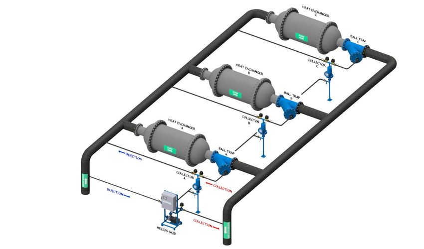
Helios Tube Cleaning System® – Application Engineering Guide

Engineered and Fabricated for Compliance & Longevity
Helios systems are designed and fabricated in the United States, and compliant with the most
exacting engineering standards on the planet. Unparalleled reliability and a life cycle outlasting
the critical performance equipment the Helios serves is the goal. A sample of engineering
standards used include:

ASME B31.9 Building Services Piping Code             ASME B31.1 Power Piping Code
ASME B31.3 Process Piping Code                       National Electric Code (NEC)

Customized Design Solutions for Applicability & Reduced Installation Cost
Custom design-build solutions are available in a wide range of materials, dimensions, and
configurations for specialized applications including seawater, elevated pressures, customer-
specific materials, and unique piping configurations.

                                                6
Helios Tube Cleaning System® – Application Engineering Guide

NOMENCLATURE
Standard Helios Tube Cleaning Systems are identified via the nomenclature below.

Example:                                     H / P150 N / RC6   / BT12 Y F1 SP

System Type                                                                Ball Trap Options
H: Base System (Skid/Collector/Ball Trap)                                  (add appropriate digits if needed)
E: Expansion Kit (Collector and Ball Trap only)                            SP: Ball Trap Service Port
                                                                           LL: Ball Trap Cover Lifting Lugs
Skid Size                                                                  C: Custom
P150: 1-1/2” conn., 3.35hp pump, for traps up to 14”
P200: 2” conn., 3.35hp pump, for traps 16” – 20”
P210: 2” conn., 5.5hp pump, for traps 24’                                  Ball Trap End Connections
                                                                           F1: ANSI Class 150 RF Flange
Skid Options                                                               BW: Butt-weld
N: none                                                                    G: Grooved (Victaulic)
B: BACnet MS/TP, BACnet IP comms module                                    C: Custom
M: MODBUS RTU RS232/485 comms module
H: High pressure (max. operating pressure 232 psig)
C: Custom configuration                                                    Ball Trap Body Style
                                                                           Y: Wye-style
Collector Size                                                             E: Elbow-style
RC6: 6” diameter Collector
RC8: 8” diameter Collector
                                                                           Ball Trap Body Size
Collector Options                                                          (nominal pipe diameter)
None: standard                                                             BT6: 6”      BT12: 12”      BT18: 18”
H: High pressure (max. operating pressure 232 pisg)                        BT8: 8”      BT14: 14”      BT20: 20
C: Custom configuration                                                    BT10: 10”     BT16: 16”     BT24: 24”

Example: H/P150N/RC6/BT12YF1SP
Base Helios Tube Cleaning System including Helios Skid, Remote Collector, and Ball Trap.
Helios P150N skid, carbon steel epoxy-coated piping, integrated 3.35hp pump with standard
145 psig operating pressure, PLC controller, optional BACnet communications module included.
Remote Collector RC6, 6” collector, standard epoxy-coated carbon steel, 145 psig max operating
pressure.
Ball Trap BT12YF1SP, 12” Y-Style Ball Trap, standard epoxy-coated carbon steel, ANSI Class
150 RF end connections, optional ball trap service port included on ball trap cover.

Custom design-build solutions are available in a wide range of materials, dimensions, and
configurations for specialized applications including seawater, elevated pressures, customer-
specific materials, larger ball traps and unique piping configurations. Contact your Innovas
sales representative for details on customized requests.

                                                       7
Helios Tube Cleaning System® – Application Engineering Guide

EQUIPMENT OVERVIEW
This section gives a short description of each major component in a Helios system.
Helios Skid - The Helios Skid is comprised of the Controls Enclosure, Pump, Application
Controller with associated piping and valves.
Ball Trap - Installed in the heat exchanger outlet pipe, the strainer inside the Ball Trap
prevents balls from escaping downstream of the Ball Trap.
Collector -This is where the balls are staged between injection cycles. The sight glass on the
Collector enables the operator to observe the number and condition of the sponge balls. In
addition, it permits the operator to observe the balls during manual operation of the system.
Helios Pump - The Helios Pump provides the flow needed to inject and collect the balls. The
balls do not flow through the pump. The actuated valves direct the water flow in the desired
directions for cleaning ball injection and collection.
Helios Controller - The controller directs all system functions by operating the actuated
valves and Helios Pump. All system operations and timers may be adjusted via the controller
touchscreen.
Actuated Valves - The actuated valves are operated by the Helios Controller in automatic
mode during normal operation.
Cleaning Balls - The sponge cleaning balls are slightly larger in diameter than the heat
exchanger or condenser tubes, so while flowing through the tubes they wipe the tubes clean.
The number of balls in the system is equal to 30-40% of the number of tubes in one pass.

                                                8
Helios Tube Cleaning System® – Application Engineering Guide

ACCESSORIES AND OPTIONS
Below are available accessories and options for configuring a Helios system.

Helios Skid Communications Module
A plug-in communications module may be selected for the Helios skid microprocessor
controller, and is available for either BACnet MS/TP BACNet IP protocol or MODBUS RTU
RS232/485 protocol. The communications modules enable seamless communication with the
facility control room for alarm notifications, monitoring, and control of the Helios system. A
complete list of available communications points is available – please contact your Innovas
sales representative to ensure you have the most updated points list.

High Pressure Components
The standard Helios skid and Collector may be upgraded to a high-pressure version, which
increases the maximum allowable operating pressure from 145 psig to 232 psig.

Ball Trap Service Port
Available for ball traps sized 10”
diameter and larger, the Ball Trap
Service Port option converts the
standard ball outlet connection on the
ball trap cover to a service port,
providing a 5” diameter inspection
port and hand-hole for quick
inspection and light cleaning of the
ball trap internal screens without the
need to remove the entire ball trap
cover flange.

Ball Trap Lifting Lugs
Lifting lugs can be added to the ball trap cover to ease in removal of the cover for cleaning or
inspection. Lifting lugs can also be added to the ball trap body upon request.

Customized Design Solutions for Increased Applicability
In addition to the options listed above, custom design-build solutions are available in a wide
range of materials, dimensions, and configurations for specialized applications including
seawater, elevated pressures, customer-specific materials, and unique piping configurations.
Contact your Innovas sales representative for details and to discuss your requirements.

                                                 9
Helios Tube Cleaning System® – Application Engineering Guide

APPLICATION NOTES AND CONSIDERATIONS
The following provides details, guidelines, and best practices for planning a Helios installation.
Helios Skid - The Helios Skid is comprised of the Controls Enclosure, Pump, Micro-processor
based Application Controller with associated piping and actuated and manual isolation
valves. For maximum flexibility and ease of installation, the skid can be located anywhere in
the mechanical room. The Helios skid includes a four-color touchscreen HMI on the front of
the controls enclosure, and the skid should be positioned to allow for easy access to the
screen. The Helios skid frame elevates and fully supports the injection/collection pump, and
the frame is equipped with mounting feet complete with anchor bolt holes. A concrete
housekeeping pad is not required.
Ball Trap - Installed in the heat exchanger outlet piping, the strainer inside the Ball Trap
prevents balls from escaping downstream. The ball trap may be installed in any position,
and may be located in vertical or horizontal pipe runs. A Y-style trap is best suited for straight
pipe runs and provides the lowest possible pressure drop. When necessary due to available
space or existing piping configuration, an elbow-style ball trap can replace a 90-degree piping
elbow.
Collector -This is where the balls are
staged between injection cycles. The sight
glass on the Collector enables the operator
to observe the number and condition of the
sponge balls. In addition, it permits the
operator to observe the balls during
manual operation of the system. The
collector should be positioned so that an
operator has unobstructed access to the
sight glass to change the cleaning balls.
Locating the collector close to the heat
exchanger reduces the length of piping
runs through which cleaning balls need to
flow and reduces the Helios pump run time requirements. The collector stand is equipped
with a mounting foot complete with anchor bolt holes, and a concrete housekeeping pad is
not required.

Debris Filtration -The Helios tube cleaning system performance is reliant on clear access to get
cleaning balls through the heat exchanger tubes. If large debris (sticks, tower fill media, chip
scale) blocks the entrance to heat exchanger tubes, the cleaning balls will not be able to enter
the tubes to effectively prevent fouling. If excessive debris is a concern, the water system
should have a debris filter upstream of the heat exchanger with a straining element sized to
protect the heat exchanger tubes (strainer openings approximately half the diameter of the
exchanger tubes). A strainer element with openings of ¼” diameter is typically sufficient.

Tube Bundles with Different Sized Tubes – Some chiller manufacturers produce condensers
that have 1” nominal tubes for the main condenser and ¾” nominal tubes for the condenser sub-
cooler. For Helios applications, it is easiest and preferred to specify a chiller wherein all the
condenser tubes are the same nominal size. The Helios system can be supplied with tube

                                                 10
Helios Tube Cleaning System® – Application Engineering Guide
inserts that are installed in the ¾” sub-cooler tubes and allow normal water flow and function
through the sub-cooler while the main bundle receives the full benefit of Helios tube cleaning.
Ball Injection Piping Tie-In
The ball injection tie-in is the location where the balls are injected into the cooling water inlet pipe,
located upstream of the heat exchanger inlet on the heat exchanger inlet piping. The injection
point tap should be at least 2 pipe diameters downstream from the skid water supply tap.
It is recommended that the location of the injection point be as close as possible to the water box
or tube sheet of the heat exchanger. This is in order to prevent balls from passing through fittings
such as control valves, filters, etc., which can negatively affect the efficacy of the tube cleaning
system.
Verify no piping connections that could siphon off cleaning balls are between the ball injection
tie-in and the Ball Trap. If the Helios system is installed on a chiller with a variable speed drive
(VSD) cooler, the supply piping tie-in for the VSD cooler must be relocated to the heat exchanger
inlet piping at least two (2) pipe diameters upstream of the cleaning ball injection tie-in.
11Helios Tube Cleaning System® – Application Engineering Guide
Once the injection point has been designated, an injection pipe and customer-supplied manual
isolation valve (full-port ball valve for 2” and smaller, 4” and larger may be butterfly valve) are
added as a branch connection to the cooling water inlet pipe.
Electrical & Controls Installation
Power Supply Wiring: The Helios Skid requires facility power for operation. Power conductors
and conduit or raceway should be installed from a facility power panel to the Helios electrical
enclosure. Power supply terminals are provided inside the skid enclosure. Refer to the system
electrical wiring diagrams for details.
Permissive Signal Wiring (hardwired): The Helios Skid is equipped as standard with terminals
for a dedicated permissive signal for each heat exchanger to be cleaned. The permissive is
utilized to indicate that sufficient water flow is present in the heat exchanger tubes prior to
cleaning ball injection. A normally open dry contact should be provided from a customer-supplied
device (condenser water pump, VFD, flow meter, differential pressure transmitter, etc.) and wired
to the terminals provided in the Helios enclosure. Refer to the system electrical wiring diagram
for details.
Permissive Signal Over BACnet or MODBUS: If the Helios Skid is equipped with an optional
BACnet or MODBUS communications module, the permissive signal may be sent from the
Building Automation System (BAS) or Distributed Control System (DCS) to the Helios Controller.
Contact your Innovas sales representative for the most recent BACnet or MODBUS points list and
consult the specific sales order and wiring diagrams for connectivity details.
Control Wiring To/From Actuated Valves on Remote Collectors: Each Remote Collector is
provided with two (2) actuated valves. Each actuator requires six (6) appropriately sized
conductors. Customer-provided control conductors and conduit or raceway should be installed
from the Helios Skid to each installed Remote Collector. Refer to the system electrical wiring
diagrams for termination details
12Helios Tube Cleaning System® – Application Engineering Guide
APPLICATION DATA
Helios Skids 4
5
Technical
Datasheet 3
2
1
Assembly Detail
13Helios Tube Cleaning System® – Application Engineering Guide
Helios Skids B
Technical
Datasheet A
Mechanical Specifications
C
* Dimensions are approximate and for reference only. Dimensions are
subject to change.
14Helios Tube Cleaning System® – Application Engineering Guide
Remote 4
Collectors
Technical 5
1
Datasheet 6
3
Assembly Detail
2
Assembly Detail
15Helios Tube Cleaning System® – Application Engineering Guide
B
Remote
Collectors
Technical
Datasheet A
Mechanical Specifications
C
* Dimensions are approximate and for reference only. Dimensions
are subject to change.
16Helios Tube Cleaning System® – Application Engineering Guide
Assembly Detail
Ball Trap Technical
Datasheet
1 1
2 3 4
2
5 5
4
3
17Helios Tube Cleaning System® – Application Engineering Guide
Y Style Ball Trap Technical
Datasheet
A
* Weights indicated are for traps with ASME B16.5
Class 150 Flanges and schedule STD carbon steel
pipe. Weights may vary for other types of flanges or
materials.
Notes:
1. Dimensions and weights are
subject to change without
notice. Upon request,
certified dimensional
drawings will be submitted for
client approval prior to start of
B fabrication.
C 2. Standard materials shown.
Consult factory for other
material options.
3. Flanged end connections
STRAINER shown. Consult factory for
REMOVAL end connection options
CLEARANC including flanged, grooved
E end, or butt-weld.
Y-Style
Ball Outlet
Ball Trap Size A B C Empty Weight Working Weight
Conn. Size
[in] [in] [in] [in] [lb] [lb]
[in]
6 19.0 16.5 21.0 1.5 140 160
8 20.0 20.5 26.0 1.5 240 300
10 27.0 24.0 31.0 1.5 370 490
12 33.0 28.0 36.0 1.5 550 740
14 34.0 30.0 40.0 1.5 780 1170
16 39.0 34.0 45.0 2.0 980 1570
18 46.0 35.0 48.0 2.0 1250 1960
20 46.0 40.0 54.0 2.0 1300 2050
24 54.0 45.5 56.0 2.0 2000 3300
18Helios Tube Cleaning System® – Application Engineering Guide
Elbow Style Ball Trap Technical
Datasheet
* Weights indicated are for traps with ASME
B16.5 Class 150 Flanges and schedule STD
C carbon steel pipe. Weights may vary for other
types of flanges or materials.
STRAINER Notes:
REMOVAL
CLEARAN 1. Dimensions and weights are subject
CE to change without notice. Upon
request, certified dimensional
B drawings will be submitted for client
D approval prior to start of fabrication.
2. Standard materials shown. Consult
factory for other material options.
3. Flanged end connections shown.
Consult factory for end connection
options including flanged, grooved
A end, or butt-weld.
19Helios Tube Cleaning System® – Application Engineering Guide
Ball Trap Pressure Drop
Specifications
Elbow-Style
Ball Trap Pressure Drop
10.0
Pressure Drop (psi)
1.0
0.1
100 1000 10000
Flow Rate (gpm)
Y-Style
Ball Trap Pressure Drop
10.0
Pressure Drop (psi)
1.0
0.1
100 1000 10000
Flow Rate (gpm)
20Helios Tube Cleaning System® – Application Engineering Guide
EXAMPLE DRAWINGS AND TECHNICAL RESOURCES
Below are example layout drawings, process flow diagrams, and resources to support
planning and design for Helios installations.
Single-Line Mechanical Installation Diagrams
Single-line mechanical installation diagrams are available for Helios system installation on one
through five heat exchangers. Please contact your Innovas sales representative to ensure that
you receive the most recent drawing version.
Single-Line Electrical & Controls Installation Diagrams
Single-line electrical and controls installation diagrams are available for Helios system
installation on one through five heat exchangers. Please contact your Innovas sales
representative to ensure that you receive the most recent drawing version.
3D CAD Files and Equipment Drawings
Three-dimensional drawings of standard Helios Skids, Collectors, and Ball Traps are available in
.stp file type. Please contact your Innovas sales representative to ensure that you receive the
most recent drawing version.
Case Studies & White Papers
Case studies and customer testimonials demonstrating the effectiveness and impact of Helios
installations can be found at this location: https://innovastechnologies.com/case-studies/
21Helios Tube Cleaning System® – Application Engineering Guide
Figure 1. Typical Configuration for Helios Tube Cleaning System® on a Single Exchanger
22Helios Tube Cleaning System® – Application Engineering Guide
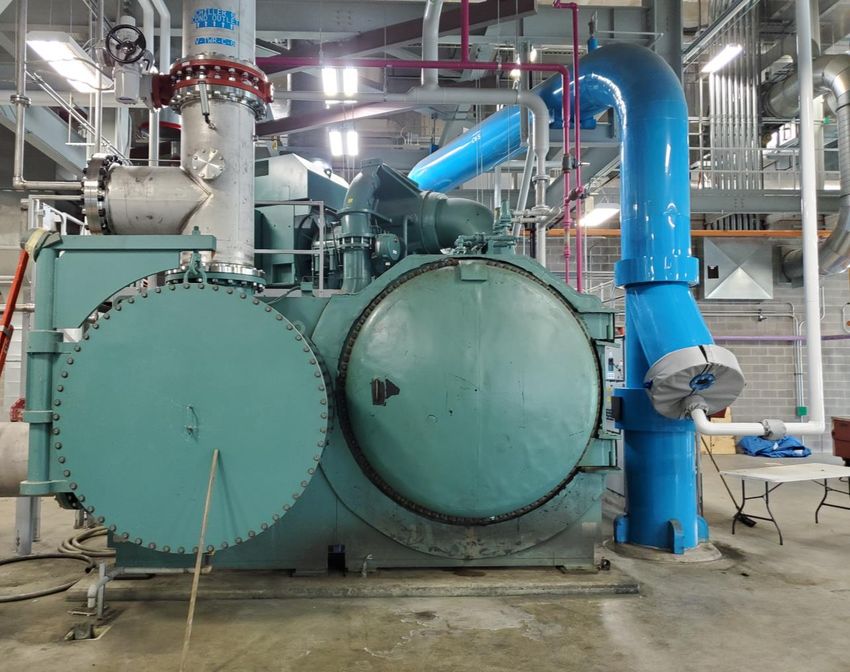
Figure 2. Typical Configuration for Helios Tube Cleaning System® on Multiple Exchangers
23Helios Tube Cleaning System® – Application Engineering Guide
Figure 3. Example Layout for Helios Tube Cleaning System® on Multiple Chillers
24Helios Tube Cleaning System® – Application Engineering Guide
GUIDE SPECIFICATIONS
AUTOMATIC TUBE CLEANING SYSTEM
PART 1 - GENERAL
1.1 Automatic tube cleaner shall be provided for the continuous online cleaning of the
condenser tubes.
1.2 The automatic tube cleaning system shall utilize sponge balls injected under water
pressure at preset intervals. Substitutes or systems using continuous flow of balls in
heat exchangers will not be permitted. Each tube cleaning system shall have one ball
collector and one ball trap serving one heat exchanger with the following
characteristics.
1.3 Mechanical systems and piping components shall be designed and manufactured in
accordance with relevant engineering standards for pressure piping systems, as
specified on the sales order: ASME 31.1 Power Piping; ASME 31.3 Process Piping,
and/or ASME B31.9 Building Services Piping.
1.4 Electrical and control systems and enclosures shall be designed and manufactured
in accordance with National Electrical Code (NEC) requirements. Enclosures shall
provide a minimum NEMA 12 protection level.
1.5 The automatic tube cleaning system supplier shall have a documented track record
of designing, providing, commissioning, and servicing automatic tube cleaning systems
meeting the requirements specified below for government agencies, public institutions
of higher learning, or publicly-traded companies for a minimum period of 5 years.
Customer references shall be made available by the automatic tube cleaning system
supplier upon request.
1.6 Warranty: Manufacturer shall repair or replace any failure caused by defects in
material and workmanship for a period of one (1) year from the date of first use or
eighteen (18) months from date of shipment, whichever occurs first.
PART 2- PRODUCTS
2.1 Cleaning ball injection shall utilize a periodic cleaning ball injection system, with
injections at programmed time intervals, and using a water pump to inject cleaning
25Helios Tube Cleaning System® – Application Engineering Guide
balls into the heat exchanger water inlet piping. The injection and collection process
shall ensure:
A. All balls shall be injected at once and reach heat exchanger tube sheet
simultaneously.
B. Balls shall randomly disperse, cleaning both central and peripheral tubes and
providing a ball cleaning run through each individual tube at least once per 24
hours of system run time.
C. The ball injection process shall not inhibit the heat exchanger cooling water
flow. Systems that interrupt cooling water flow and/or change flow direction in
the heat exchanger tubes will not be permitted.
D. Cleaning balls shall not travel through pump impellers where they may get
sheared or damaged, resulting in frequent replacement or reduction of cleaning
ball life.
E. The cleaning ball injection process shall be capable of interlocking with a
permissive signal indicating sufficient cooling water flow is recognized in the
heat exchanger prior to cleaning ball injection.
F. The cleaning ball collection process shall be accomplished via the same pump
and controller as the cleaning ball injection process.
G. In order to maximize heat transfer process efficiency, the collection process
shall not route heat exchanger outlet water back to the heat exchanger inlet
during collection.
2.2 The Collector is the site for ball residence before and after ball injection. Each
Collector shall be constructed of carbon steel with internal and external epoxy painting,
and all materials and components shall be rated for cooling water system design
pressure and temperature in accordance with the requirements of Section 1.2. Each
Collector shall serve a single heat exchanger. The Collector shall provide an observation
window for quick inspection of ball condition and provide access for replacement of
cleaning balls.
2.3 The Controller shall be a micro-processor based, programmable application
controller utilized to manage cleaning of heat exchangers, and shall be capable of
communication with existing or new Building Automation Systems (BAS) and/or Direct
26Helios Tube Cleaning System® – Application Engineering Guide
Digital Controls (DDC) at the installation site via BACnet or MODBUS communication
protocols as specified on the sales order, without Protocol Translators, Communication
Bridges, or Gateways.
The controller shall provide a local human machine interface (HMI) and shall provide a
graphical user interface (GUI) touchscreen for local indication and control of
operations.
The controller shall allow local control, presetting of ball injection times and frequency
of cleaning each heat exchanger.
The controller shall provide alarms and notifications of the following conditions:
- System Fault - Pump Fault - Ball Change Required
- Valve Fault - Permissive Fault
2.4 The injection pump shall be of centrifugal design, close-coupled to a totally
enclosed fan- cooled motor, and sized to inject cleaning balls and water into the heat
exchanger inlet piping. Cleaning balls shall not be circulated through the pump impeller.
One water pump will be used to inject balls into one heat exchanger at a time. The
pump shall be installed in a manner that does not recirculate effluent water. A system
allowing mixing of inlet and outlet heat exchanger cooling water shall not be permitted.
2.5 Pump Skid and Collector piping shall be designed and constructed in accordance
with the applicable engineering standards referenced in Section 1.2.
2.6 A Ball Trap shall be installed in each heat exchanger's water outlet piping. Ball Traps
shall have the following characteristics:
A. Ball traps shall be cylindrical shaped containing perforated stainless steel
screens. Primary ball collection area shall be located outside the heat exchanger
outlet pipe primary flow with ball collection at end of the ball trap.
B. Ball trap strainer open area shall be at minimum 3.0 times larger than the cross-
27Helios Tube Cleaning System® – Application Engineering Guide
sectional area of the piping nominal size.
C. The ball trap may not have any moving parts, reducing wear and tear and
associated maintenance requirement. Systems using mechanically actuated
screens or slotted bars will not be permitted.
D. The ball trap shall guarantee 100% zero ball escape to downstream processes.
2.7 Equipment shall be as manufactured by lnnovas or approved equal.
PART 3- EXECUTION
3.1 The tube cleaning system supplier shall provide factory-trained and authorized
personnel to perform equipment commissioning and training of site maintenance staff.
3.2 The tube cleaning system supplier must be able to provide maintenance services by
factory trained and authorized personnel.
END OF SECTION
28Technical Questions For more information about Innovas Technologies products and services please visit: www.innovastechnologies.com. Or contact us at: E-mail: info@innovastechnologies.com Toll Free: 1-877-897-6564
You can also read