HI-EFFICIENT DIRECT VENT WALL FURNACE - Cozy Heaters
←
→
Page content transcription
If your browser does not render page correctly, please read the page content below
HI-EFFICIENT DIRECT VENT
                                                               WALL FURNACE

                               Installation and Operating Instructions
                    Natural Gas - HEDV253A, HEDV403A                 |     Propane Gas - HEDV254A, HEDV404A

                                                                                                                                     HEDV 40

        ! WARNING: If the information in these instructions
      is not followed exactly, a fire or explosion may result
      causing property damage, personal injury or loss of life.
                                                                                        HEDV 25
  — Do not store or use gasoline or other flammable vapors and
    liquids in the vicinity of this or any other appliance.

  — WHAT TO DO IF YOU SMELL GAS                                                       - The coating selected to provide longer life to the
      • Do not try to light any appliance.                                              heat exchanger may smoke slightly upon initial
                                                                                        firing. Please provide adequate ventilation if this
      • Do not touch any electrical switch; do not use any phone                        occurs.
        in your building.
                                                                                      - Installation, maintenance, service, troubleshooting
      • Immediately call your gas supplier from a neighbor’s
                                                                                        & repairs must be performed by a qualified service
        phone. Follow the gas supplier’s instructions.
                                                                                        agency. DO NOT attempt any of these procedures
      • If you cannot reach your gas supplier, call the fire                            if you are not qualified as this could expose you
        department.                                                                     to property damage, personal injury, or loss of life
                                                                                        and will invalidate all warranties.
  — Installation and service must be performed by a qualified
    installer, service agency or the gas supplier.                                    - This unit is for residential use only and is not approved
                                                                                        for installation in greenhouses, or environments
                                                                                        involving dusty, wet, corrosive, or explosive conditions.
                                                                                        Such conditions will invalidate the warranty and may
   INSTALLER: Leave this manual with the appliance.                                     create unsafe conditions.
   CONSUMER: Retain this manual for future reference.                                 - This appliance may be installed in an aftermarket,
                                                                                        permanently located, manufactured home (USA
                                                                                        only) or mobile home, where not prohibited by local
   ! WARNING: This product can expose you to chemicals including epichlorohydrin        codes. This appliance is only for use with the type
 which is known to the State of California to cause cancer and birth defects and/or     of gas indicated on the rating plate. This appliance
 other reproductive harm. For information go to www.p65warnings.ca.gov.                 is not convertible for use with other gases, unless
                                                                                        a certified kit is used.

WARNING: OPERATION OF THIS FURNACE WITHOUT THE PROPERLY INSTALLED, FACTORY FURNISHED VENT SYSTEM AND
VENT CAP COULD RESULT IN CARBON MONOXIDE (C.O.) POISONING AND POSSIBLE DEATH. FOR YOUR SAFETY, THIS FURNACE
AND THE VENT SYSTEM SHOULD BE INSPECTED AT LEAST ANNUALLY BY A QUALIFIED SERVICE TECHNICIAN.

Cozy Heating Systems, LLC | cozyheaters.com | 888-444-1212 | 250 West Laurel Street | Colton, CA 92324

                                                                  Page 1                                                             1017952-A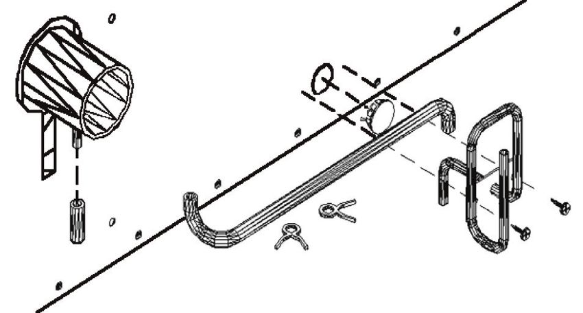
CONTENTS                                          READ CAREFULLY BEFORE INSTALLING UNIT

Before Installation                                             These installation instructions are a general guide and do not
 Standards ............................................ 2       supersede applicable local codes and ordinances. Before planning
 Specifications ...................................... 3        or making the installation be sure it complies with all phases of the
                                                                local heating code. (Or, in the absence of local codes, with the latest
 Introduction ......................................... 3
                                                                edition of National Fuel Gas Code, ANSI.Z223.1, or CAN1-B149).
 Safety .............................................. 3 - 4
 Venting ................................................ 4     The appliance, when installed, must be electrically grounded in
 Clearances ...................................... 5 - 6        accordance with local codes, or in the absence of local codes, with
 Location .............................................. 7      the latest edition of National Electrical Code ANSI / NFPA 70, or
                                                                Canadian Electrical Code CSA-C22.1.

Installation                                                    All of the ANSI and NFPA standards referred to in these installation
                                                                instructions are the ones that were applicable at the time the design
  Locating the Vent Opening ................... 8
                                                                of this appliance was certified.
  Rough-In Gas Supply .......................... 8
  Installing Vent System ......................... 9
  Installing Heater ................................. 10           NFPA Standards:
                                                                   NATIONAL FIRE PROTECTION
Maintenance                                                        ASSOCIATION
 Operating Instructions ........................           11      1 Batterymarch Park
 Proper Burner Flame .........................             12      Quincy, Massachusetts | USA 02169-7471
 Cleaning the Burner ...........................           12
 Burner Orifice & Orifice Chart ............               12
 Wiring ................................................   13     ANSI & Canadian Standards:
 Sequence of Operations ....................               14     CSA GROUP
    Kits:                                                         178 Rexdale Boulevard,
•   HEVK-5 Vent Exhaust ........................           15     Toronto, Ontario | Canada M9W 1R3
•   HEVE-5 Vent Enclosure ....................             16
•   HEEL-1 90º ........................................    16   The design of this appliance was certified to comply with the latest
•   18900 Condensate .............................         17   edition of ANSI Z21.86 and CSA 2.32.

    Maintenance Instructions ................... 18
                                                                Installer must leave these instructions with the consumer, have
    Installations In The State Of                               them complete, and return the warranty card.
    Massachusetts..................................... 18
    Service Records ................................ 19
    Troubleshooting Charts ................ 20 - 21                The State of Massachusetts requires that installation
                                                                   and service of a gas appliance be performed by a
Parts                                                              plumber or gas fitter licensed in the Commonwealth of
                                                                   Massachusetts. See page 18.
  HEDV Part List ........................... 22 - 23

Warranty .............................................. 24

1017952-A                                                          Page 2
SPECIFICATIONS & DIMENSIONS
Your Direct Vent Wall Furnace is shipped complete in one carton. This carton contains the furnace, vent cap, collector box, vent
exhaust tube, air inlet tube, wall template with rough-in dimensions, installation and operating instructions, and wall thermostat.
MODEL NUMBERS HEDV253A HEDV403A HEDV254A HEDV404A
Gas Type Natural Natural Propane Propane
Height 32-1/4” 30-1/2” 32-1/4” 30-1/2”
Width 24-1/2” 34-5/8” 24-1/2” 34-5/8”
Depth 9-3/4” 9-3/4” 9-3/4” 9-3/4”
Input (BTU / HR) 25,000 40,000 25,000 40,000
Type of Control 24 V. 24 V. 24 V. 24 V.
Cubic Feet per Minute (CFM) 200 500 200 500
AMPS 1.88 2.18 1.88 2.18
Gas Connection 3/8” 3/8” 3/8” 3/8”
Center Vent to Floor (Adj.) 12-1/2” 12-1/2” 12-1/2” 12-1/2”
Min.–Max. Wall Thickness 35” – 2” 35” – 2” 35” – 2” 35” – 2”
Approximate Weight 100 lbs 120 lbs 100 lbs 120 lbs
INTRODUCTION
THIS IS A GAS-FIRED DRAFT INDUCED, POWER DEPENDENT DIRECT VENT WALL FURNACE THAT WILL OPERATE
SAFELY AND PROVIDE AN EFFICIENT SOURCE OF HEAT WHEN INSTALLED, OPERATED AND MAINTAINED AS
RECOMMENDED IN THESE INSTALLATION AND OPERATING INSTRUCTIONS. READ THESE INSTRUCTIONS
THOROUGHLY BEFORE INSTALLING, SERVICING, OR USING THE APPLIANCE. IF YOU DO NOT UNDERSTAND ANY PART
OF THESE INSTRUCTIONS CONSULT LOCAL AUTHORITIES, OTHER QUALIFIED INSTALLER, SERVICE TECHNICIAN,
THE GAS SUPPLIER OR THE MANUFACTURER.
SAFETY
1. Improper installation, adjustment, alteration, service, 8. Have your wall furnace and vent system inspected at
or maintenance can cause property damage, bodily least annually by a qualified service technician.
injury, or death.
9. Before cleaning or servicing, turn off the gas and
2. Use in other than a residential application may result allow furnace to cool.
in unsatisfactory performance, may create unsafe
conditions and will invalidate the warranty. 10. Do not operate wall furnace without all components
properly installed (top, front, etc.).
3. The installation must conform with local codes or in
the absence of local codes wtih the National Fuel 11. Due to high temperatures, the appliance should be
Gas Code, ANSI Z223.1/NFPA 54, Natural Gas and located out of traffic and away from furniture & drapes.
Propane Installation Code, CSA B149.1. 12. Children and adults should be alerted to the hazards
4. DO NOT INSTALL THIS FURNACE IN A of high surface temperature and should stay away to
RECREATIONAL VEHICLE OR TRAILER. avoid burns or clothing ignition.
5. Do not operate wall furnace unless it is connected to 13. Young children should be carefully supervised when
the factory supplied vent system with vent cap in place. they are in the same room as the appliance.
6. Check the rating label attached to the wall furnace to be 14. Clothing or other flammable material should not be
sure it is equipped for the type gas you intend to use. placed on or near the appliance.
7. Never use a match, candle, flame or other source of 15. INSTALLATION AND REPAIR SHOULD BE DONE
ignition to check for gas leaks. Use only soapy water BY A QUALIFIED SERVICE TECHNICIAN. THE
or liquid detergent. APPLIANCE SHOULD BE INSPECTED BEFORE
Page 3 1017952-ASAFETY - Continued
USE AND AT LEAST ANNUALLY BY A QUALIFIED 21. Do not use this appliance if any part has been under
SERVICE TECHNICIAN. More frequent cleaning water. Immediately call a qualified service technician
may be required due to excessive lint from to inspect the appliance and to replace any part of the
carpeting, bedding material, etc. It is imperative that control system and any gas control which has been
control compartments, burners, and circulating air under water.
passageways of the appliance be kept clean. 22. It is necessary to replace damaged gaskets or sealing
16. Do not install in a closet, alcove, or small hallway material within the vent or air intake system. Failure to
where the furnace could be isolated from the space to do so may result in property damage, personal injury
be heated by closing a door. or loss of life.
17. Do not put anything around the furnace or vent cap that 23. Any safety screen or guard removed for servicing
will obstruct the flow of combustion and ventilation air. must be replaced prior to operating heater.
18. The appliance, when installed, must be electrically 24. A gas appliance must not be connected to a chimney
grounded in accordance with local codes or, in the flue serving a separate solid fuel burning appliance.
absence of local codes, with the latest edition of 25. The appliance area must be kept clear and free from
National Electrical Code, ANSI/NFPA 70, or Canadian combustilbe materials, gasoline and other flammable
Electrical Code, CSA C22.1, if an external electrical vapors and liquids.
source is utilized.
26. Any safety screen or guard removed for servicing
19. Never operate this furnace without the sight glass in an appliance must be replaced prior to operating the
place or with the glass broken or missing. appliance.
20. If it is suspected that rising water may enter the furnace,
turn off the gas immediately.
VENTING
! WARNING: CARBON MONOXIDE POISONING HAZARD
Failure to follow the steps outlined below for each appliance connected to the venting system being placed into
operation could result in carbon monoxide poisoning or death.
The following steps shall be followed for each appliance connected to the venting system being placed into operation, while
all other appliances connected to the venting system are not in operation:
1) Seal any unused openings in the venting system. 6) Follow the lighting instructions. Place the appliance being
2) Inspect the venting system for proper size and horizontal inspected into operation. Adjust the thermostat so appliance
pitch, as required in the National Fuel Gas Code, ANSI is operating continuously.
Z223.1/NFPA 54 or the Natural Gas and Propane Installation 7) Test for spillage from draft hood equipped appliances at
Code, CSA B149.1 and these instructions. Determine that the draft hood relief opening after 5 minutes of main burner
there is no blockage or restriction, leakage, corrosion and operation. Use the flame of a match or candle.
other deficiencies which could cause an unsafe condition.
8) If improper venting is observed during any of the above
3) As far as practical, close all building doors and windows tests, the venting system must be corrected in accordance
and all doors between the space in which the appliance(s) with the National Fuel Gas Code, ANSI Z223.1/NFPA 54
connected to the venting system are located and other and/or Natural Gas and Propane Installation Code, CSA
spaces of the building. B149.1.
4) Close fireplace dampers. 9) After it has been determined that each appliance
5) Turn on clothes dryers and any appliance not connected connected to the venting system properly vents when tested
to the venting system. Turn on any exhaust fans, such as as outlined above, return doors, windows, exhaust fans,
range hoods and bathroom exhausts, so they are operating fireplace dampers and any other gas-fired burning appliance
at maximum speed. Do not operate a summer exhaust fan. to their previous conditions of use.
1017952-A Page 4CLEARANCES
G
D H
A E
B
B
Inside B
Corner C FIXED
BLE D
OPERA CLOSE I
Detail FIXED
D M
CLOSE
B
BLE
OPERA
F
= Vent Terminal B J K
A
= Air Supply Inlet B
FIG. 1
= Area where terminal is
not permitted
CANADIAN
REFERENCE LETTER TO DRAWING INSTALLATIONS* U.S. INSTALLATIONS**
A Clearance above grade, veranda, porch, deck, or balcony 12 Inches (30 cm) 12 Inches (30 cm)
B Clearance to window or door that may be opened 12 Inches (30 cm) 9 Inches (23 cm)
C Clearance to permanently closed window 12 Inches (30 cm) 9 Inches (23 cm)
D Vertical clearance to ventilated soffit located above the
terminal within a horizontal distance of 2 Feet (61 cm) 18 Inches (46 cm) 18 Inches (46 cm)
from the center line of the terminal
E Clearance to unventilated soffit 18 Inches (46 cm) 18 Inches (46 cm)
F Clearance to outside corner 12 Inches (30 cm) 12 Inches (30 cm)
G Clearance to inside corner 12 Inches (30 cm) 12 Inches (30 cm)
3 Feet (91 cm) within a height
H Clearance to each side of center line extended above Clearance in accordance
15 Feet (4.5m) above the meter /
meter/regulator assembly with local installation codes &
regulator assembly
requirements of the gas supplier
I Clearance to service regulator vent outlet 3 Feet (91 cm)
J Clearance to nonmechanical air supply inlet to building or
12 Inches (30 cm) 12 Inches (30 cm)
the combustion air inlet to any other appliance
3 Feet (91 cm) above if within
K Clearance to a mechanical air supply inlet 6 Feet (1.83 m)
10 Feet (3 m) horizontally
7 Feet (2.13m)
L Clearance above paved sidewalk or paved driveway A vent shall not terminate directly
located on public property above a sidewalk or paved driveway
that is located between two single Clearance in accordance
family dwellings & serves both dwellings with local installation codes &
12 Inches (30 cm) requirements of the gas supplier
Permitted only if veranda, porch,
M Clearance under veranda, porch, deck, or balcony
deck, or balcony is fully open on a
minimum of two sides
*In accordance with the current CSA-B149.1 **In aaccordance with the current ANSI
Natural Gas and Propane Installation Code Z223.1 / NFPA 54 National Fuel Gas Code
Page 5 1017952-ACLEARANCES - Continued
ATTENTION: ALL CANADIAN CONTRACTORS/INSTALLERS: Before installing this heater into a multi-family
! hi-rise exceeding four stories, contact the local building code inspector to verify the building construction complies
with the Progressive Collapse requirements as listed in the National Building Code of Canada 2005.
1. As you face the heater, the clearance to a side wall on the 7. Clearances around vent cap must be maintained to assure
right side is 0” (Fig. 2), and the left side is 1” (Fig. 2). adequate combustion and ventilation air.
2. The minimum clearance from the top of the heater to the 8. Clearances listed are minimum. Adequate accessibility
ceiling or any projecting overhang is 10”. (See Figure 2). clearances for servicing must be maintained.
3. The minimum clearance from the bottom of the heater to 9. RESIDENTIAL GARAGE INSTALLATION:
the floor, or the top surface of carpeting, tile, etc. is 0”. Gas utilization equipment in residential garages shall be
(See Figure 2). installed so that all burners and burner ignition devices
4. When the appliance is installed directly on carpeting, tile are located not less than 18 inches (46 cm) above the
or other combustible material other than wood flooring, floor. You must build a platform 18” above floor, the full
the appliance shall be installed on a metal or wood panel width and depth of the heater, including the rear trim
extending the full width and depth of the appliance. kit. HEATER IS NOT DESIGNED TO HANG ON WALL.
Unit should be located or protected so it is not subject to
5. The minimum clearance from the edge of the vent cap to damage by a moving vehicle. Use care in selecting a good
any overhanging obstruction, perpendicular side wall, or location within the garage. DO NOT locate the appliance
corner of building is 12”. (See Figure 1). where heated air will be directed onto a nearby parked
6. Vent cap must be located at least 9” from any opening that vehicle. Paint may discolor or rubber may harden and
would allow combustion products to enter the building, crack. DO NOT allow open or closed containers of paint,
windows, doors, etc., and 12” above the ground or gasoline or other liquids having flammable vapors to be
shrubbery (See Figure 1). stored or used in the same area as the heater
Do not install vent cap in a window well. Provisions must
be made to prevent snow accumulation from infringing on
vent cap clearances.
FIG. 2
CEILING OR OVERHANG
CEILING OR OVERHANG
1” 10” 0”
1” 0” Left Right
10” Side Side
Left Right
Side Side Wall Wall
Wall Wall
0” FLOOR
0” FLOOR
HEDV40 HEDV25
1017952-A Page 6LOCATION OPTIONAL KITS
1. The wall furnace must be installed on an outside wall, 1. HEVK-5 - To extend vent 5 foot from heater. This will allow
unless optional Kit No. HEVK-5 is used. vent cap to be installed above grade from basement or to
2. For most efficient performance, locate furnace as centrally an outside wall.
as possible in the area to be heated and where occupants A total of 3 kits with 2 additional elbows may be used.
may move about freely without coming into contact with
the cabinet, and within reach of a 115V wall outlet.
3. If the furnace is installed in a basement, a 12” clearance For additional kit installation
must be maintained between ground level and the bottom instructions, see page 15.
of the vent cap. Do not install furnace where vent cap
will terminate in a window well or any other opening
below ground level. (See Figure 3). Do not allow snow
accumulation to build up within 12” of the vent cap. FIG. 3
12” MINIMUM
ABOVE GRADE
WITHOUT
EXCAVATION
Page 7 1017952-AINSTALLATION
ATTENTION: ALL CANADIAN CONTRACTORS/INSTALLERS: Before installing this heater into a multi-family
hi-rise exceeding four stories, contact the local building code inspector to verify the building construction complies
with the Progressive Collapse requirements as listed in the National Building Code of Canada 2005.
WARNING: FAILURE TO FOLLOW THESE INSTRUCTIONS CAREFULLY COULD RESULT IN POOR
! PERFORMANCE, PROPERTY DAMAGE, PERSONAL INJURY, OR DEATH.
Step 1. LOCATE VENT OPENING Step 2. ROUGH-IN GAS SUPPLY (See Figure 5)
(Requires 3-1/2” diameter wall opening). Install at least 3/8” gas supply line. Contact local gas
supplier if any questions.
a) Select area on wall where heater will be installed. Using
template (packed with heater) mark shaded area where
hole can be cut and to locate the wall brackets. (See Manual shut-off valve must
Figure 4). be accessible in room where
heater is installed
b) Locate studs on each side of this area.
c) Mark location for 3-1/2” diameter hole between studs. Wall Gas
Valve
Hole should be offset to miss studs. (See Figure 4).
d) Check outside wall at this location for proper clearances
around vent cap. (See Figure 1). Manual shut-off valve with
1/8” NPT plugged tapping Back
e) Cut vent openings into both the inside and outside walls, must be accessible in room of Heater
where heater is installed
being sure to maintain level across both openings.
3/8” Black Iron Pipe
Gas Supply
Template
Drip Leg
FIG. 5
Install a drip leg in gas supply line immediately upstream from
the gas connection to heater (see local codes), and provide
a 1/8” N.P.T. plugged tapping, accessible for test gauge
connection and an individual manual shut off valve accessible
Shaded Area within room where heater is installed. (See Figure 5). The heater
and its individual shut off valve must be disconnected from the
gas supply piping system during any pressure testing of that
Wall Studs
16” O.C. system at test pressures in excess of 1/2 psig (3.5 Pa). The
heater must be isolated from the gas supply piping system by
closing its individual manual shut off valve during any pressure
testing of the gas supply piping system at test pressures equal
FIG. 4 to or less than 1/2 psig (3.5 Pa). Test all connections for leaks
using a soapy solution. NEVER USE AN OPEN FLAME TO
TEST FOR LEAKS.
MAXIMUM INLET GAS MINIMUM INLET GAS
SUPPLY PRESSURE SUPPLY PRESSURE
1/2 p.s.i. or 14” w.c. 4.5” w.c. 11.0” w.c.
or
Natural or Propane Gas Natural Gas Propane Gas
1017952-A Page 8INSTALLATION - Continued
Step 3. INSTALLING VENT SYSTEM 5” - 32” WALL THICKNESS (12.7 cm - 81.3 cm)
a) Use only factory supplied parts. Do not attempt to modify in any way. To do so could cause a system imbalance resulting in poor
performance and/or unsafe operating conditions.
b) Slide collection box pipes through cutout & secure collection box to inside wall. Anchors (not supplied) may be required. See Figure 5.
c) From outside house, mark collection box pipes and cut off 1/2” beyond outside wall.
d) Slide vent cap pipes onto collection box pipes and push in until flange is flush against house. Secure vent cap assembly to outside
wall with a slight downward slope. This will prevent water from entering and allow condensation to drain. Caulk around the edges
of the vent cap mounting plate.
NOTE: It may be necessary to build a metal or wood frame to provide a flat surface for the mounting plate to be flush against or
to attain the 5” minimum wall thickness.
FIG. 6 HEDV25 HEDV40
6-1/2” 6-3/8”
(16.51 cm) ( 16.19 cm)
4-1/8”
4” (10.2 cm) (10.2 cm)
Trim Kit Brackets
Trim Kit Brackets
Gas Inlet
Gas Inlet
Air Intake
29-5/8”
(75.2 cm) 25” Air Intake
(63.5 cm)
25-1/16” 20-11/16”
(63.7 cm) (52.5 cm) Flue Outlet
Flue Outlet
7-9/16” 7-9/16”
(19.2 cm) (19.2 cm)
5-7/8” 6-1/8”
(14.9 cm) (15.6 cm)
FIG. 7 FIG. 8
Collection Box Vent
Assembly Cap
Assembly
Vent Cap
Mounting
Plate
Page 9 1017952-AINSTALLATION - Continued
Step 4. INSTALLING HEATER
a) Locate (and mark) wall mounting bracket location on wall h) Locate factory installed thermostat wires extending from
using template supplied. rear of the heater. Connect 24 V. thermostat wall thermostat
b) Secure wall brackets to wall, anchors (not provided) may be (provided) using a maximum 20’ of thermostat wire. Do
required. NOT splice thermostat wire.
c) Secure trim kit brackets to back of heater using eight #8 i) Secure right and left trim side panels to the wall and trim kit
brackets with eight #8 screws provided. (See Figure 9). This
screws provided. (See Figure 9).
will space the back of the heater 5” from the wall.
d) Slide heater to approximately 5” of wall.
j) Secure trim top to trim sides using four #8 screws provided.
e) Secure air intake hose to back of heater and the collector
k) Plug three-pronged factory wired power cord into a properly
box assembly using hose clamps provided. (See Figure 8). grounded 115 Volt electrical outlet. NEVER use an extension
f) Secure vent exhaust tube to exhaust tube on back of heater cord. If homeowner desires, heater can be hard wired by a
and the exhaust tube on the collection box assembly using licensed electrician. See local electrical codes.
hose clamps provided. (See Figure 8). l) Turn the manual gas control valve on. Check all connections
g) Connect 3/8” minimum gas supply line to manual cut-off for leaks using a soapy solution. NEVER check for leaks
valve on back of the heater. (See Figure 5). with an open flame.
HEATER IS NOW INSTALLED, FOLLOW LIGHTING INSTRUCTIONS TO PLACE HEATER INTO SERVICE. FRONT
PANEL MUST BE REMOVED FOR ACCESS TO LIGHTING INSTRUCTIONS AND GAS CONTROL.
FIG. 9
Trim Kit
Top
1/2”
Bushing Trim Kit
Left Side
Trim Kit Right
Side
Trim Kit Bracket (x4)
1017952-A Page 10OPERATING INSTRUCTIONS
FOR YOUR SAFETY READ BEFORE OPERATING
A. This appliance does not have a pilot. It • If you cannot reach your gas supplier, call
WARNING: is equipped with an ignition device which the fire department.
automatically lights the burner. Do not try C. Use only your hand to push in or turn the gas
If you do not to light the burner by hand.
follow these control knob. Never use tools. If the knob
B. BEFORE OPERATING smell all around will not push in or turn by hand, don’t try to
instructions
the appliance area for gas. Be sure to repair it, call a qualified service technician.
exactly, a fire or
smell next to the floor because some gas is Force or attempted repair may result in a fire
explosion may heavier than air and will settle on the floor. or explosion.
result causing
property WHAT TO DO IF YOU SMELL GAS: D. Do not use this appliance if any part has been
damage, • DO NOT try to light any appliance. under water. Immediately call a qualified
• DO NOT touch any electric switch. service technician to inspect the appliance
personal injury
and to replace any part of the control system
or loss of life. • DO NOT use any phone in your building. and any gas control which has been under
• Immediately call your gas supplier from a water.
neighbor’s phone. Follow the gas supplier’s
instructions.
OPERATING INSTRUCTIONS
1. STOP! Read safety information on this label. 11. If the appliance does not operate, follow instructions
2. Set the thermostat to the lowest setting. “To Turn Off Gas To Appliance” and call your service
technician or gas supplier.
3. Turn off all electric power to the appliance.
12. Replace cabinet.
4. This appliance is equipped with an ignition device
which automatically lights the burner. Do not try to light
the burner by hand.
5. Remove cabinet to access gas control knob.
6. Turn gas control knob clockwise to “off”. Do not
force. See Figure 10.
7. Wait five (5) minutes to clear out any gas. If you smell
gas, STOP! Follow “B” in safety information on this
label. If you don’t smell gas, go to next step.
Gas control knob shown
8. Turn gas control knob counterclockwise to “ON”. in “OFF” position
9. Turn on all electric power to the appliance.
10. Set thermostat to desired setting. Fig. 10
TO TURN OFF GAS TO APPLIANCE
1. Set the thermostat to lowest setting.
2. Turn off all electric power to the appliance if service is to be performed.
3. Turn gas control knob clockwise to “OFF”. Do not force.
Page 11 1017952-ABURNER
PROPER BURNER FLAME
FIG. 11
Primary Flame
The burner flame may be observed by raising the sight glass
cover. A proper flame will have a dark blue inner mantle, Burner
with a lighter blue outer mantle that extends from the burner
into the heat exchanger tube, (see Figure 11).
There is no primary air adjustment on the burner, and
proper flame is assured since the correct manifold pressure
and orificing have been done at the factory.
Secondary Flame
Heat Exchanger Tube
TO REMOVE MAIN BURNER
FOR INSPECTION AND CLEANING
1. Turn off all electrical supply to heater. NOTE: The furnace and all components must be
2. Turn off gas supply. inspected at least annually by a qualified service
3. Remove front panel. technician. This should include the burner, heat
exchanger, and vent system. Be sure that the flow
4. Unplug wire to direct spark ignitor and sensor.
of combustion and ventilation air are not obstructed
See Figure 12.
and that all hoses are undamaged, and all clamps
5. Disconnect vacuum hose from burner box. are securely tightented.
6. Remove screws holding burner box top to burner box.
See Figure 12.
7. Remove burner plate and burner box top. Take care not
to contact, or strain ignitor in any way as it is extremely FIG. 12
fragile. See Figure 12.
8. Remove 2 nuts holding burner bracket. See Figure 12. Maxitrol
Gas
9. Slide burners toward heat exchanger and lift up from
Valve
rear and back. See Figure 12.
10. Clean or replace as needed.
11. Reinstall by reversing Steps 9–1.
Burner
Box Top
BURNER ORIFICE
This appliance equipped only for altitudes 0 - 2,000 ft. Manifold
Appliance input ratings are based on sea level operation
and need not be changed for operation up to 2,000 feet
(609.9 m) elevation. For operation at elevations above Burner
2,000 feet (609.9 m).
Burner
The BTU input must be reduced 4% per 1,000 ft. Orifice Direct
Bracket
change must be completed by a qualified installer or service Spark Ignitor
technician. See the following orifice chart for the proper
orifice drill size for a specific elevation.
NATURAL GAS - (SPECIFIC ELEVATIONS) PROPANE GAS - (SPECIFIC ELEVATIONS)
0 to 2,000 - 4,000 - 6,000 - 8,000 - 0 to 2,000 - 4,000 - 6,000 - 8,000 -
Model No. 2,000’ 4,000’ 6,000’ 8,000’ 10,000’ Model No. 2,000’ 4,000’ 6,000’ 8,000’ 10,000’
HEDV253A 51 52 52 53 54 HEDV254A 58 60 62 63 64
HEDV403A 45 47 48 49 50 HEDV404A 55 55 56 56 57
1017952-A Page 12WIRING
WARNING: THIS IS A GAS-FIRED APPLIANCE. KEEP THE AREA CLEAR OF GASOLINE AND OTHER
! FLAMMABLE VAPORS AND LIQUIDS. ALL COMBUSTIBLE MATERIAL MUST BE KEPT CLEAR OF THIS
AREA TO AVOID FIRE OR EXPLOSION.
This appliance is equipped with a three prong power cord with grounding plug. For your protection against shock hazard, this
appliance should be plugged directly into a properly grounded three-prong receptacle. Do not cut or remove the grounding
prong from this plug.
NOTE: If any of the original wire supplied with this appliance
has to be replaced, it must be replaced with type 105ºC wire CAUTION: Label all wires prior to disconnection when
or its equivalent. servicing controls. Wiring errors can cause improper
and dangerous operation.
Verify proper operation after servicing.
FIG. 13
Thermostat HEDV25-A HEDV25-A
HEDV40-A HEDV40-A
Pressure
Switch Black PICTORIAL LADDER
Purple Red White
Gas Gas Valve
Valve Black
Red Pressure Switch
R G W C Draft Inducer
Yellow
CMB Blower
Limit Limit Switch
Orange Switch L1
Circulating
GROUND ACC Blower
24V Thermostat 24 VAC
ACB COOL
24 VAC
Circuit Board
Circuit Board
Transformer
115 VAC
Black Black
Draft Inducer
Green
Black
Circulating Blower
WIRING DIAGRAM | HEDV253A, HEDV254A, HEDV403A & HEDV404A
Page 13 1017952-AHEDV SEQUENCE OF OPERATIONS
Heater in Thermostat
Stand-by Calls for Heat
4 Sec. 90 Sec.
Power Pressure Spark Gas Valve Burner
Blower
on to Draft Switch Closes YES Ignition Opens Gas Flow Flame YES
On
Inducer Inducer Proved Energized to Burner Proved
NO NO
Inducer Continues to Run 15 Second Inter Purge
Pressure Switch Closes 3 Attempts for Ignition YES
YES
Proving Inducer
NO
NO
One Hour Lock Out
180 Sec.
30 Sec.
Gas Valve
Heat Thermostat Draft Blower Heater
Closes Gas Flow
Cycle Satisfied Inducer Off in Standby
to Burners Off
STEP #: 4) Spark ignition begins. 9) Thermostat satisfied.
5) Gas flow to burner. 10) Gas flow off to burner.
1) Thermostat calls for heat. 6) Burner ignition proven. 11) Draft inducer off.
2) Draft Inducer turns on. 7) Circulating Blower on. 12) Circulating Blowers off.
3) Pressure switch closes. 8) Heater burns through heating cycle. 13) Heater in stand-by.
NOTE: If there is a malfunction during Steps 3, 5 or 6 the operation sequence will stop at that point. For Steps 5 or 6, if the
malfunction still occurs after two additional attempts, the control will lock out for one hour. For purpose of testing, the one hour
lockout can be overridden by resetting the thermostat or interrupting the electrical power.
1017952-A Page 145’ VENT EXHAUST KIT INSTALLATION INSTRUCTIONS - ( HEVK-5 )
WARNING: Use only Cozy Heating Systems factory-supplied parts and kits. Failure to do so could result in
! loss of life, personal injury, property damage, or unsatisfactory performance. This kit must be installed by a
qualified installer or service technician.
CONTENTS OF KIT STEP 1. LOCATE VENT OPENING
1-1. Select location on outside wall that vent will exit through.
A 2” x 3” 1-2. Check outside for proper clearances around vent cap. See installation instructions.
Steel Coupling 1-3. Mark & cut 3-1/2” hole through both inside and outside walls, being sure to maintain level across both openings.
1-4. Measure wall thickness. Mark and cut off both intake and exhaust pipes to 1/2” beyond outside wall.
P/N: 72532, Qty: 1 1-5. Secure collection box to wall. Wall anchors, not provided, may be required.
B 2” x 5’ STEP 2. INSTALL HEATER
Black Flocked Tube
2-1. Select location on wall where heater will be installed.
P/N: 72575, Qty: 1 2-2. Using wall template supplied with heater, mark location for trim kit wall brackets.
2-3. Attach brackets to wall (wall anchors, not provided may be required) and back of heater.
C 2” x 6’ Use screws provided on back of heater.
Black Flex Tubing 2-4. Slide heater into position and secure brackets togehter. This should position back of heater 5” off wall.
P/N: 72612, Qty: 1 2-5. Select direction vent will exit trim kit, left, right, or straight up.
2-6. Before installing trim kit remove knockout on this side.
D Support Brackets
P/N: 41515, Qty: 2 STEP 3. INSTALL VENT
3-1. Remove and discard P/N 72611 2”x24” black flex tubing from air inlet. (Save hose clamp).
E Center Bracket 3-2. Attach P/N 72612 2”x6’ black flex tubing to air inlet. Secure with P/N 72593 2” hose clamp.
P/N: 41520, Qty: 1 3-3. Slide P/N 72575 2”x5’ flocked tube through trim kit opening (knockout) and attach to P/N 72610 orange silicone 90E
elbow supplied with heater. Secure with 2” hose clamp.
F 2” Hose Clamps 3-4. Attach P/N 41515 support brackets to wall. Wall anchors, not provided, may be required. Postion support brackets
P/N: 72593, Qty: 8 within 8” from side of trim kit and end of pipe. Secure flex tubing and flocked tube to brackets using 2” hose clamps.
3-5. Attach P/N 41520 center bracket 2-1/2’ from pipe end and insert flex tube through bracket. This will prevent the flex
G 2” x 3” tube from touching the black flocked exhaust tube.
Black Silicone 3-6. Connect flex air intake tube and flocked exhaust tube to collection box.
Wrapped Coupling 3-7. Complete gas connection and attach trim kit to brackets.
3-8. Follow lighting instructions.
P/N: 72578, Qty: 1
FIG. 14
C
A
G
D
SPECIAL NOTES: B
a) You may use up to three HEVK-5 Kits for a total of 15’ vent
E
extension with two additional elbows. DO NOT EXTEND VENT
D
BEYOND 15’ OR USE MORE THAN THREE TOTAL ELBOWS (one elbow
comes with the heater).
b) To connect two vent kits together use P/N 72532 2”x3” steel coupling. Secure with 2” hose F
clamps.
c) If you are using one, two, or three kits, after installation is complete you will discard 2 P/N 72593 hose clamps
and one P/N 72532 steel coupling.
d) If you need to make a 90E offset you will need to order P/N HEEL-1 90E Elbow Kit. Two offsets require two kits.
e) If complete vent extension is horizontal, pipes may be sloped down slightly to allow any condensate to drain through the exhaust
pipe to the outside. DO NOT ALLOW TO DRAIN ONTO WALKWAY. If any part of vent extension is vertical or local codes do not allow
draining of condensate to outside you must add P/N 18900 Condensate Kit.
f) For cosmetic purposes, the addition of the HEVK-5 Kit can be enclosed by adding a HEVE-5 Vent Enclosure Kit. To completely enclose
the HEVK-5 Kit one HEVE-5 will be needed for each HEVK-5 used.
Page 15 1017952-AHEVE-5 VENT ENCLOSURE KIT INSTALLATION INSTRUCTIONS
FIG. 15
THIS KIT MUST BE INSTALLED BY A QUALIFIED
INSTALLER OR SERVICE TECHNICIAN
Step 1. Position end of Part No. 41610 enclosure body to heater trim kit
where pipes exit trim kit, centering pipes inside body and attach
to wall. Wall anchors (not provided) may be required. Collector
box may be behind HEVE-5 Kit.
Step 2. Cut to fit enclosure panel 1” beyond end of vent run. Insert Part
No. 41620 End Cap and attach using three #8 screws provided.
SPECIAL INSTRUCTIONS:
Step 3. If more than one HEVE-5 Kit is used, attach Part No. 72604
Trim Kit where ends meet.
Step 4. If making a 90º turn, measure 1” beyond outside turn and cut off
enclosure panel.
- Notch panel on surface of direction turn is being made to
allow pipes to pass through into next HEVE-5 Kit.
- Attach second panel to wall and attach Part No. 72604 Trim
Kit where two bodies meet.
- Install end cap Part No. 41620.
HEEL-1 90º ELBOW KIT
Contains 1 only P/N 72613 - (90º Elbow 2”)
1017952-A Page 1618900 CONDENSATE KIT INSTRUCTIONS
WARNING: Always use this kit when the vent has a vertical run, or where local codes prohibit draining
condensate to the outside. Use only Cozy Heating Systems supplied parts. Failure to use factory
! supplied parts or to follow these instructions may result in unsatisfactory performance, property
damage, personal injury and/or loss of life.
BEFORE beginning kit installation, open carton & identify the following components. CONTENTS OF KIT
Step 1. Set thermostat to “Off” and allow heater to cool. A Condensate
Pan Assembly
Step 2. Turn off gas supply to heater. P/N: 18910
Step 3. Turn off electric power to heater. B Condensate
Trap Assembly
Step 4. Remove the cabinet. P/N: 72618
Step 5. Loosen the two wing nuts located in the heater base. See Figure 16. C 3/8” Flexible
Step 6. Slide the condensate pan into the bottom of the heater with slots in tabs onto the Hose / Tubing
weld studs and under the wing nuts. Use care to not rip the insulation in bottom of P/N: 72538
heater. Tighten the wing nuts to secure condensate pan. D 3/8” Hose
See Figure 16. Clamp
P/N: 72539, Qty: 2
Step 7. Remove and discard the button plug located at center lower area of heater back.
E #8 x 1/2” Screws
Step 8. Attach condensate trap to heater back so bottom of trap is inside the bottom of P/N: 50606, Qty: 2
the condensate pan. Secure using the (2) #8 screws provided. Fill trap with water.
See Figure 17.
Step 9. Remove and discard plastic cap from bottom of the draft inducer drain tube.
See Figure 17.
Step 10. Connect the tubing to the draft inducer drain tube and the condensate trap.
Secure both ends with two 3/8” hose clamps provided. See Figure 17.
Step 11. Fill the condensate pan with water.
Step 12. Reverse steps 4 – 1. Follow lighting instructions to place heater in operation.
FIG. 16 FIG. 17
80190
Casing B
Black Plug
Weld Pin (2) Inducer
Drain
Wing Nuts (2) Cap
A D
C E
The water level in the condensate pan must be checked and maintained to completely
! WARNING: cover the condensate trap. The water provides a seal to prevent combustion products from
coming through the condensate trap and entering the living area.
Page 17 1017952-AMAINTENANCE INSTRUCTIONS
• FOR PROPER AND SAFE OPERATION KEEP FURNACE & FURNACE AREA CLEAN
At regular intervals turn control valve to off, let cool and clean inside control and heat exchanger compartment. To clean
front panel use only a damp cloth, do not use any kind of solvent or cleaning fluid that could leave a residue to burn or
give off fumes when furnace is turned on.
• CHECKING THE FURNACE
Have the furnace checked, cleaned, and repaired by a qualified service technician. Check venting system, and burner
operation prior to use each year.
• SERVICE & MAINTENANCE
Follow a regular service and maintenance schedule for safe and efficient operation.
• DO NOT OBSTRUCT COMBUSTION & VENTILATION AIR
Examine the venting system as a routine part of the safety performance check on an annual basis.
• REMOVED HEAT EXCHANGER
If the heat exchanger is removed, check the heat exchanger intake gasket and draft inducer gasket and replace if there
is any sign of damage. Be sure all gaskets are in place when the heat exchanger is replaced.
• DAMAGED GASKETS
Failure to replace any gasket that has been damaged may result in property damage, personal injury or loss of life. Oil the
bearings of the fan motor every 6 months with S.A.E. 20 oil.
INSTALLATIONS IN THE STATE OF MASSACHUSETTS
All installations in the State of Massachusetts must use b. Have battery back-up power;
the following requirements when installing, maintaining or c. Meet ANSI/UL 2034 Standards and comply with NFPA
operating direct-vent propane or natural gas-fired space 720 (2005 Edition); and
heaters. d. Have been approved and listed by a Nationally
Recognized Testing Laboratory as recognized under
For direct-vent appliances, mechanical-vent heating 527 CMR.
appliances or domestic hot water equipment, where the
bottom of the vent terminal and the air intake is installed A CARBON MONOXIDE DETECTOR SHALL:
below four feet above grade the following requirements must a. Be located in the room that houses the appliance
be satisfied: or equipment;
b. Be either hard-wired or battery powered or both; and
1. If there is not one already present, on each floor level c. Shall comply with NFPA 720 (2005 Edition).
where there are bedroom(s), a carbon monoxide 3. A product-approved vent terminal must be used, and if
detector and alarm shall be placed in the living area applicable, a product-approved air intake must be
outside the bedroom(s). The carbon monoxide detector used. Installation shall be in strict compliance with the
shall comply with NFPA 720 (2005 Edition). manufacturer’s instructions. A copy of the installation
2. A carbon monoxide detector shall be located in the instructions shall remain with the appliance or
room that houses the appliance or equipment equipment at the completion of the installation.
and shall: 4. A metal or plastic identification plate shall be mounted
a. Be powered by the same electrical circuit as the at the exterior of the building, four feet directly above
appliance or equipment such that only one service the location of vent terminal. The plate shall be of
switch services both the appliance and the carbon sufficient size to be easily read from a distance of eight
monoxide detector. feet away, and read “Gas Vent Directly Below”.
1017952-A Page 18SERVICE RECORDS Page 19 1017952-A
TROUBLESHOOTING CHART
                                         For use by a qualified service technician.

 SYMPTOM                  POSSIBLE CAUSES                          CORRECTIVE ACTION - (To be performed by Contractor)

 Flame          1. Defective operator section of valve.       1. Replace valve.
 Too Large      2. Burner orifice too large.                  2. Check with local gas company for proper orifice - size and replace.
                3. If installed above 2,000 ft.               3. See burner orifice section, Page 12.

 Yellow         1. Clogged burner ports.                      1. Remove burners and check for obstructions in throats, ports, and
 Burner Flame                                                    orifices. Clean - but do not enlarge ports or orifices.
                2. Obstruction around vent cap.               2. Make sure area around vent cap is clear, be sure vent system is sealed.

 Gas Odor       1. Gas leak.                                  1. See Page 1.

 Delayed        1. Low gas pressure.                          1. Check gas supply pressure.
 Ignition       2. Igniter not properly located.              2. Check ignitor location and correct if necessary.

 Failure        1. Main gas off.                              1. Open manual gas valve.
 to Ignite      2. Thermostat not set                         2. Set thermostat to higher temperature.
                   high enough to call for heat.
                3. Clogged burner orifice.                    3.   Clean burner orifices (do not enlarge).
                4. Incorrect wiring.                          4.   Check wiring diagram.
                5. Defective valve.                           5.   Replace valve.
                6. No power to unit.                          6.   Plug in power supply cord. Check 115 V. wall outlet.

 Burner Won’t   1. Defective or damaged                       1. Can be checked by removing wire from control board terminal.
 Turn Off          thermostat wire or thermostat.                If burner goes off, replace thermostat.
                2. Thermostat location.                       2. Re-locate out of drafts, hot, or cold spots.
                3. Defective or sticking valve.               3. Replace valve.
                4. Excessive gas pressure.                    4. Contact utility supplying gas.
                5. Defective or damaged thermostat.           5. Replace thermostat.

 Incorrect      1. Gas input not checked.                     1. Re-check gas input.
 Gas Input      2. Clogged orifices.                          2. Clean orifices with a smooth wood toothpick, do not enlarge.

 Not            1. Furnace undersized.                        1. This is especially true when a dwelling or room is enlarged. Have the heat
 Enough                                                          loss calculated and compare to furnace output. Your gas company can
 Heat                                                            supply you with this information. If furnace is undersized, replace with
                                                                 correct size unit.
                2. Thermostat temperature set too low.        2. Raise thermostat temperature setting.
                3. Incorrect supply pressure.                 3. Check supply pressure.

 Too Much       1. Temperature set too high.                  1. Lower temperature setting.
 Heat           2. Combination control valve stuck open.      2. Replace combination control valve.

 Main Burner    1.   Defective flame sensor.                  1. Check voltage and replace if low.
 Goes Out       2.   Input too high.                          2. Check input rate.
 During         3.   Sight glass not air tight.               3. Tighten screws securing sight glass. Check & replace gasket if needed.
 Normal
 Operation      4.   Vent tubes not properly installed        4. Follow instructions. Check both exhaust and air intake tubes, and vent cap.
                     or sealed.                                  Be sure all gaskets are in place and properly sealed. Use only tubes and
                                                                 vent cap supplied. Do not alter vent tubes or cap.
                5. Limit switch opens.                        5. Check for blockage of discharge air.
                6. Exhaust or Air Intake tubes blocked.       6. Check for and remove any obstruction to incoming circulating air.

1017952-A                                                  Page 20
TROUBLESHOOTING CHART
For use by a qualified service technician.
To assist in diagnosing and servicing, this heater is equipped with a self-diagnosing control module. Should a
malfunction occur, the green indicator light on the control module will flash a varying number of times indicating
the circuit in which malfunction is located.
# OF REASON FOR POSSIBLE CORRECTIVE ACTION
FLASHES INDICATION CAUSES (To be performed by Contractor)
Slow Normal Operation,
Flash NO CALL FOR HEAT
Fast Normal Operation,
Flash CALL FOR HEAT
2 System Lockout 1. Defective ignitor. 1. Replace ignitor.
Failed to Detect or 2. Ignitor cable defective. 2. Replace ignitor cable.
Sustain Flame 3. Ignitor cable disconnected. 3. Connect ignitor cable.
4. Manual gas valve in “OFF” 4. Turn manual gas valve to “ON.”
position. No gas to valve.
5. Defective wire to gas valve. 5. Replace defective wire.
6. Wire to gas valve disconnected. 6. Connect gas valve wire.
7. Obstruction to vent outlet. 7. Remove obstruction.
8. Obstruction to air inlet. 8. Remove obstruction.
3 Pressure 1. Defective pressure switch. 1. Replace pressure switch.
Switch Open 2. Pressure switch tubing damaged, 2. Replace damaged tubing.
or Closed kinked or collapsed.
3. Pressure switch tubing 3. Connect pressure switch tubing.
disconnected.
4. Defective draft inducer. 4. Replace draft inducer.
5. Pressure switch tubing to the 5 Reverse tubing connections on pressure switch.
wrong connection.
4 Limit Switch 1. Defective limit switch. 1. Replace limit switch.
Opens 2. Damaged limit switch wire. 2. Replace damaged wire.
3. Limit switch wire disconnected. 3. Connect limit switch wire.
4. Blockage in front of front panel. 4. Remove blockage.
5. Heater over rate. 5. Check orifice, pressures, rate.
5 Flame Sensed 1. Defective gas valve. 1. Replace gas valve.
Gas Valve 2. Defective control module. 2. Replace control module.
Not Energized
Steady Internal Failure 1. Defective control module. 1. Replace control module.
Light - No (Control module failure and
Flashes power on self-check)
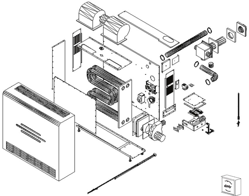
Page 21 1017952-AHI-EFFICIENT DIRECT VENT WALL FURNACE PARTS LIST
Natural Gas: HEDV253A & HEDV403A | Propane Gas: HEDV254A & HEDV404A
2
42
31 32
40 30
44 3
29
33
34 35
36
36
38
26 41 37
1 23
5
4 25 43
24 22
21
28 20
17 15
HOW TO 24 19
PROPERLY
ORDER PARTS: 9 11 14
12 13 18
In addition to the 47 10
8 16
part description 6
and numbers,
please be prepared 27
to provide:
- Model Number
- Serial Number 46
- Type of Gas Used
This information can be found on the
rating plate that is attached to the heater.
PART # PART # PART # PART #
REF. # PART DESCRIPTION HEDV253A HEDV254A HEDV403A HEDV404A
1 Cabinet 18020 18020 18520 18520
2 Circulating Blower 72501 72501 72500 72500
3 Limit Switch 72671 72671 72670 72670
4 Front Heat Shield 72531 72531 72530 72530
5 Tubular Heat Exchanger 18120 18120 18620 18620
6 Cabinet Base Assembly 18120 18120 18620 18620
7 Leg Leveler - (4 Per) 80009 80009 80009 80009
8 Draft Inducer Gasket - ( 7-3/4 x 9” ) 72565 72565 72565 72565
9 Draft Inducer - (Mounting Plate Gasket) 72563 72563 72563 72563
10 Draft Inducer 72506 72506 72506 72506
11 Sight Glass Frame 18185 18185 18185 18185
12 Sight Glass 70150 70150 70150 70150
13 Sight Glass Gasket - ( 2-5/8 x 1-3/8” ) 72564 72564 72564 72564
14 Ignitor 64009 64009 64009 64009
NOTE: Parts & schematic drawings on current models are shown at: cozyheaters.com | Specifications subject to change without notice.
1017952-A Page 22HI-EFFICIENT DIRECT VENT WALL FURNACE PARTS LIST
Natural Gas: HEDV253A & HEDV403A | Propane Gas: HEDV254A & HEDV404A
ATTN: Contractors and Qualified Service Technicians: We only sell parts through our wholesalers.
For prompt parts service, contact the wholesaler from which you purchased your Cozy heater.
PART # PART # PART # PART #
REF. # PART DESCRIPTION HEDV253A HEDV254A HEDV403A HEDV404A
15 Ignitor Cable 64210 64210 64210 64210
16 Burner Orifice - (Requires 2) *95251 *95258 *72156 *72139
17 Burner *72528 *72528 *72528 *72528
18 Manifold 72640 72640 72640 72640
19 Burner Box Assembly 18150 18150 18150 18150
20 Burner Box Top Gasket - ( 6-3/4 x 6-1/2” ) 72567 72567 72567 72567
21 Burner Box Top 18165 18165 18165 18165
22 Gas Valve 64590 64591 64590 64591
23 Gas Valve Support Bracket 18180 18180 18180 18180
24 Burner Box Mounting Gasket - ( 7-3/4 x 3-1/2” ) 72566 72566 72566 72566
25 Transformer 78069 78069 78069 78069
26 Circuit Board 64625 64625 64625 64625
27 Wiring Harness 72675 72675 72675 72675
28 Pressure Switch 72517 72517 72518 72518
29 Casing Back 18090 18090 18590 18590
30 Air Intake Hose 72611 72611 72611 72611
31 2” Hose Clamp (4 Per) 72593 72593 72593 72593
32 Vent Cap Assembly 18250 18250 18650 18650
33 Vent Cap Gasket - ( 4-3/32 x 4-3/32” ) 72608 72608 72608 72608
34 Collection Box Assembly 18225 18225 18225 18225
35 Collection Box Gasket - ( 5-7/16 x 5-7/16” ) 72607 72607 72607 72607
36 Collection Box Cap 72587 72587 72587 72587
37 Vent Exhaust Tube 72610 72610 72610 72610
38 Trim Kit Bracket - (Requires 4) 18320 18320 18320 18320
39 Wall Mounting Bracket - (Requires 4) 18315 18315 18315 18315
40 Trim Kit - (Left Side Panel) 18310 18310 18310 18310
41 Trim Kit - (Right Side Panel) 18305 18305 18305 18305
42 Trim Kit - (Top) 18300 18300 18700 18700
43 HEDV Wire Bracket 18190 18190 18190 18190
44 Liner - (Left Side) 18110 18110 18610 18610
45 Liner - (Top) 18075 18075 N/A N/A
46 Wall Thermostat, 24 Volt 78355 78355 78355 78355
47 Draft Inducer Mounting Plate 18200 18200 18200 18200
n/a Thermostat Wire 20’ 74518 74518 74518 74518
n/a Power Cord 64205 64205 64205 64205
n/a Manual Shut-off Valve - (Off-On) 64074 64074 64074 64074
n/a Condensate Kit 18900 18900 18900 18900
*Requires 2
NOTE: Parts & schematic drawings on current models are shown at: cozyheaters.com | Specifications subject to change without notice.
Page 23 1017952-ALIMITED WARRANTY
The manufacturer, Williams Comfort Products, Some states do not allow limitation on how long
warrants this Cozy wall furnace or heater to the an implied warranty lasts, and some states do not
original purchaser under the following conditions: ANY allow the exclusion or limitation of incidental
WARRANTY CONSIDERATIONS ARE CONTINGENT or consequential damages, so the above
ON INSTALLATION BY A QUALIFIED INSTALLER limitations or exclusions may not apply to you.
(CONTRACTOR). SELF-INSTALLATION IS PROHIBITED 2. This warranty does not include any charge for labor
AND WILL INVALIDATE YOUR WARRANTY. or installation.
3. This warranty does not extend to painted surfaces
LIMITED ONE-YEAR WARRANTY or to damage or defects resulting from accident,
1. Any part thereof which proves to be defective alteration, misuses or abuse or improper installation.
in material or workmanship within one year from date of 4. This warranty does not cover claims which do not
original purchase for use will be replaced at the involve defective workmanship or materials.
Manufacturer’s option, FOB to its factory.
DUTIES OF THE CONSUMER
2. No liability is assumed by the Manufacturer for
removal or installation labor costs, nor for freight 1. The heating equipment must be installed by a
or delivery charges. qualified installer and operated in accordance
with the installation and homeowner’s
LIMITED EXTENDED WARRANTY instructions furnished with the equipment.
1. In addition to the above limited one year
warranty on the complete unit, any combustion 2. Any travel, diagnostic costs, service labor,
chamber which burns out or rusts under normal and labor to repair the defective unit will be the
installation, use and service conditions during a responsibility of the owner.
period of nine years following expiration of the 3. A bill of sale, canceled check, payment record
one-year warranty period will be exchanged for a or permit should be kept to verify purchase date to
like or functionally similar part. establish the warranty period.
2. No liability is assumed by the Manufacturer for 4. Have the installer enter the requested
removal or installation labor costs, nor for freight information in the space below.
or delivery charges. GENERAL
LIMITATIONS 1. The manufacturer neither assumes nor authorizes
1. THIS LIMITED WARRANTY IS THE ONLY any person to assume for it any other obligation
WARRANTY MADE BY THE MANUFACTURER, or liability in connection with said equipment.
IMPLIED WARRANTIES OF MERCHANTABILITY 2. Service under this warranty should be obtained
OR FITNESS FOR ANY PARTICULAR PURPOSE by contacting your dealer. Provide the dealer with
ARE LIMITED TO THE SAME ONE YEAR TERM the model number, serial number, and purchase
AS THE EXPRESS WARRANTY. UNDER NO date verification.
CIRCUMSTANCES SHALL THE MANUFACTURER
BE LIABLE FOR INCIDENTAL, CONSEQUENTIAL, 3. If, within a reasonable time after contacting your
SPECIAL OR CONTINGENT DAMAGES OR dealer, satisfactory service has not been received,
EXPENSES ARISING DIRECTLY OR INDIRECTLY contact: Customer Service Department,
FROM ANY DEFECT IN THE PRODUCT OR ANY 250 West Laurel Street, Colton, CA 92324
COMPONENT OR FROM THE USE THEREOF. THE for assistance.
REMEDIES SET FORTH HEREIN ARE THE 4. THIS WARRANTY GIVES YOU SPECIFIC LEGAL
EXCLUSIVE REMEDIES AVAILABLE TO THE USER RIGHTS AND YOU MAY ALSO HAVE OTHER RIGHTS
AND ARE IN LIEU OF ALL OTHER REMEDIES. WHICH VARY FROM STATE TO STATE.
TO REGISTER YOUR FURNACE: GO ONLINE TO THE COZY HEATERS WEBSITE AT:
www.cozyheaters.com/warranty-registration/
1017952-A Page 24Manual Español
CALENTADOR DE ALTA
EFICIENCIA CON TOBERA
TEM
E
AS D CIÓN LL
SIS ALEFA
C
C DIRECTA PARA MURO
C
Instalación e Instrucciones de Operación
Gas Natural - HEDV253A, HEDV403A | Gas Propano - HEDV254A, HEDV404A
! ADVERTENCIA: Si no se sigue exactamente la
información en estas instrucciones, puede ocurrir un
incendio o una explosión que provocaría daños a la HEDV 40
propiedad, lesiones personales o la pérdida de la vida.
— No almacene ni utilice gasolina ni otros líquidos y vapores
inflamables en las proximidades de este o cualquier otro
dispositivo.
— QUÉ DEBE HACER SI HUELE GAS
• No intente encender ningún dispositivo. HEDV 25
• No toque ningún interruptor eléctrico; no utilice ningún
teléfono del edificio. - El revestimiento seleccionado para proporcionar
• Llame inmediatamente a su proveedor de gas desde una mayor vida útil al intercambiador de calor
puede humear levemente con el encendido
el teléfono de un vecino. Siga las instrucciones del
inicial. Por favor proporcione ventilación adecuada
proveedor de gas. si esto ocurre.
• Si no puede comunicarse con el proveedor de gas, llame - La instalación, el mantenimiento, el servicio, la
al departamento de bomberos. solución de problemas y las reparaciones deben ser
realizados por una agencia de servicio calificada.
— La instalación y el servicio deben ser realizados por NO intente ninguno de estos procedimientos si
un instalador certificado, una agencia de servicio o el no está calificado, ya que esto podría exponerlo
proveedor de gas. a daños a la propiedad, lesiones personales o
pérdida de vidas e invalidará todas las garantías.
- Esta unidad es solo para uso residencial y no está
aprobada para instalación en invernaderos, o
INSTALADOR: Deje este manual junto al dispositivo. ambientes con condiciones polvorientas, mojadas,
corrosivas, o explosivas. Tales condiciones invalidarán
CONSUMIDOR: Conserve este manual para referenia futura. la garantía y pueden crear condiciones inseguras.
- Este aparato se puede instalar en una casa
prefabricada, de ubicacion permanente (unicamente
! ADVERTENCIA: Este producto puede exponerlo a productos en los E.E. U.U.) o, donde el codigo local no lo
químicos, incluida la epiclorhidrina, que el estado de California sabe prohiba, en una casa movil. Este aparato solo se
debe usar con el tipo de gas indicado en la placa
que causan cáncer y defectos de nacimiento y / u otros daños re- de datos tecnicos, y no se puede convertir para
productivos. Para mas información, www.p65warnings.ca.gov visite uso con otros tipos de gas, a menos que se use un
equipo certificado.
ADVERTENCIA: HACER FUNCIONAR ESTE CALENTADOR SIN EL SISTEMA DE VENTILACIÓN Y LA VALVULA DE VENTEO DE
FABRICA DEBIDAMENTE INSTALADOS PUEDE RESULTAR EN ENVENENAMIENTO POR MONÓXIDO DE CARBONO (CO) E INCLUSO
LA MUERTE. POR SU SEGURIDAD UN TÉCNICO DE SERVICIO CALIFICADO DEBE REVISAR POR LO MENOS UNA VEZ AL AÑO ESTE
CALENTADOR Y EL SISTEMA VENTILACION.
Cozy Heating Systems, LLC | cozyheaters.com | 888-444-1212 | 250 West Laurel Street | Colton, CA 92324
Manual Español Página 1 1017953-AYou can also read