INLINE 400 PRESSURE BOOSTING SYSTEM - Installation and Operation Manual - franklinwater.com - Little Giant ...
←
→
Page content transcription
If your browser does not render page correctly, please read the page content below

INLINE 400 PRESSURE BOOSTING SYSTEM
                    Installation and Operation Manual

                                        franklinwater.com
COPYRIGHT INFORMATION
                                                                                                                   Franklin Electric
                                                                                                                   Technical Publications
                                                                                                                   9255 Coverdale Road
                                                                                                                   Fort Wayne, IN 46809

Copyright © 2019, Franklin Electric, Co., Inc. All rights reserved.
The entire contents of this publication are copyrighted under United States law and protected by worldwide copyright laws and treaty
provisions. No part of this material may be copied, reproduced, distributed, republished, downloaded, displayed, posted or transmitted
in any form by any means, including electronic, mechanical, photocopying, recording, or otherwise, without prior written permission of
Franklin Electric. You may download one copy of the publication from www.franklinwater.com onto a single computer for your personal,
                                                                         35TU                     U35T

non-commercial internal use only. This is a single copy, single use license, not a transfer of title, and is subject to the following restric-
tions: you may not modify the materials, use them for any commercial purpose, display them publicly, or remove any copyright or other
proprietary notices from them.
The information in this publication is provided for reference only and is subject to change without notice. While every effort has been
made to ensure the accuracy of this manual at the time of release, ongoing product improvements and updates can render copies obso-
lete. Refer to www.franklinwater.com for the current version.
              35TU                     U35T

This publication is provided “as is” without warranties of any kind, either express or implied. To the fullest extent possible pursuant to
applicable law, Franklin Electric disclaims all warranties, express or implied, including but not limited to, implied warranties of merchant-
ability, fitness for a particular purpose, and non-infringement of intellectual property rights or other violation of rights. Franklin Electric
does not warrant or make any representations regarding the use, validity, accuracy, or reliability of the material in this publication.
Under no circumstances, including but not limited to, negligence, shall Franklin Electric be liable for any direct, indirect, special, inciden-
tal, consequential, or other damages, including, but not limited to, loss of data, property damage, or expense arising from, or in any way
connected with, installation, operation, use, or maintenance of the product based on the material in this manual.
Trademarks used in this publication:
The trademarks, service marks, and logos used in this publication are registered and unregistered trademarks of Franklin Electric and
others. You are not granted, expressly, by implication, estoppel or otherwise, any license or right to use any trademark, service mark, or
logo displayed on this site, without the express written permission of Franklin Electric.
FE Logo and Design® and Inline 400™ are registered trademarks of Franklin Electric.
NEMA is a trademark of The Association of Electrical Equipment and Medical Imaging Manufacturers.

2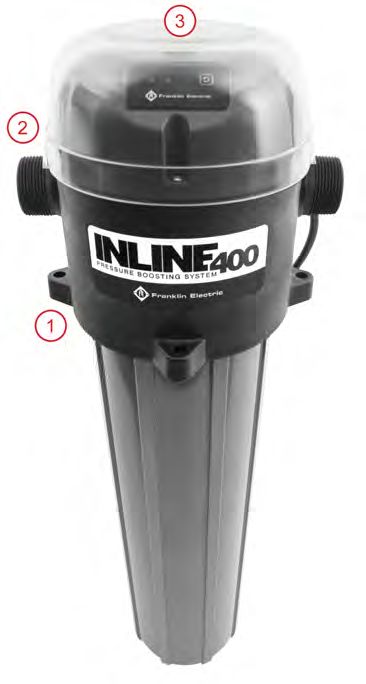
TABLE OF CONTENTS

TABLE OF CONTENTS
SAFETY INSTRUCTIONS - - - - - - - - - - - - - - - -           -   -   -   -   -   -   -   -   -   -   -   -   -   -   -   -   -   -   -   -   -   -    4
PRODUCT INFORMATION- - - - - - - - - - - - - - - -            -   -   -   -   -   -   -   -   -   -   -   -   -   -   -   -   -   -   -   -   -   -    5
    Description - - - - - - - - - - - - - - - - - - - -       -   -   -   -   -   -   -   -   -   -   -   -   -   -   -   -   -   -   -   -   -   -    5
    Features- - - - - - - - - - - - - - - - - - - - - -       -   -   -   -   -   -   -   -   -   -   -   -   -   -   -   -   -   -   -   -   -   -    5
    Models - - - - - - - - - - - - - - - - - - - - - -        -   -   -   -   -   -   -   -   -   -   -   -   -   -   -   -   -   -   -   -   -   -    5
    Pump Components - - - - - - - - - - - - - - - -           -   -   -   -   -   -   -   -   -   -   -   -   -   -   -   -   -   -   -   -   -   -    6
    What’s in the Box - - - - - - - - - - - - - - - - -       -   -   -   -   -   -   -   -   -   -   -   -   -   -   -   -   -   -   -   -   -   -    6
INSTALLATION - - - - - - - - - - - - - - - - - - - -          -   -   -   -   -   -   -   -   -   -   -   -   -   -   -   -   -   -   -   -   -   -    7
    Environmental Requirements- - - - - - - - - - - -         -   -   -   -   -   -   -   -   -   -   -   -   -   -   -   -   -   -   -   -   -   -    7
         Special Considerations for Outdoor Use- - - - -      -   -   -   -   -   -   -   -   -   -   -   -   -   -   -   -   -   -   -   -   -   -    7
         Location - - - - - - - - - - - - - - - - - - -       -   -   -   -   -   -   -   -   -   -   -   -   -   -   -   -   -   -   -   -   -   -    7
         Pressure Tank - - - - - - - - - - - - - - - - -      -   -   -   -   -   -   -   -   -   -   -   -   -   -   -   -   -   -   -   -   -   -    7
    Inline 400 Mounting - - - - - - - - - - - - - - - -       -   -   -   -   -   -   -   -   -   -   -   -   -   -   -   -   -   -   -   -   -   -    8
         Orientation of the Inline 400 - - - - - - - - - -    -   -   -   -   -   -   -   -   -   -   -   -   -   -   -   -   -   -   -   -   -   -    8
         Flow Direction- - - - - - - - - - - - - - - - -      -   -   -   -   -   -   -   -   -   -   -   -   -   -   -   -   -   -   -   -   -   -    9
         Plumbing Considerations for Priming Purposes -       -   -   -   -   -   -   -   -   -   -   -   -   -   -   -   -   -   -   -   -   -   -    9
    Typical Installation Diagram - - - - - - - - - - - -      -   -   -   -   -   -   -   -   -   -   -   -   -   -   -   -   -   -   -   -   -   -   10
    Plumbing Installation - - - - - - - - - - - - - - -       -   -   -   -   -   -   -   -   -   -   -   -   -   -   -   -   -   -   -   -   -   -   11
    Electrical Installation - - - - - - - - - - - - - - - -   -   -   -   -   -   -   -   -   -   -   -   -   -   -   -   -   -   -   -   -   -   -   12
OPERATION - - - - - - - - - - - - - - - - - - - - - -         -   -   -   -   -   -   -   -   -   -   -   -   -   -   -   -   -   -   -   -   -   -   12
    Priming the System - - - - - - - - - - - - - - - -        -   -   -   -   -   -   -   -   -   -   -   -   -   -   -   -   -   -   -   -   -   -   12
         Adjusting Performance - - - - - - - - - - - -        -   -   -   -   -   -   -   -   -   -   -   -   -   -   -   -   -   -   -   -   -   -   13
         Effect of System Leaks- - - - - - - - - - - - -      -   -   -   -   -   -   -   -   -   -   -   -   -   -   -   -   -   -   -   -   -   -   14
    Status Display - - - - - - - - - - - - - - - - - - -      -   -   -   -   -   -   -   -   -   -   -   -   -   -   -   -   -   -   -   -   -   -   15
    Protection Features - - - - - - - - - - - - - - - -       -   -   -   -   -   -   -   -   -   -   -   -   -   -   -   -   -   -   -   -   -   -   16
         Maximum Inlet Pressure - - - - - - - - - - - -       -   -   -   -   -   -   -   -   -   -   -   -   -   -   -   -   -   -   -   -   -   -   16
         Maximum Output Pressure- - - - - - - - - - -         -   -   -   -   -   -   -   -   -   -   -   -   -   -   -   -   -   -   -   -   -   -   16
         Maximum Operating Temperature - - - - - - -          -   -   -   -   -   -   -   -   -   -   -   -   -   -   -   -   -   -   -   -   -   -   16
MAINTENANCE - - - - - - - - - - - - - - - - - - - -           -   -   -   -   -   -   -   -   -   -   -   -   -   -   -   -   -   -   -   -   -   -   17
    Draining the System - - - - - - - - - - - - - - - -       -   -   -   -   -   -   -   -   -   -   -   -   -   -   -   -   -   -   -   -   -   -   17
    Cleaning the Flow Piston - - - - - - - - - - - - - -      -   -   -   -   -   -   -   -   -   -   -   -   -   -   -   -   -   -   -   -   -   -   17
         Re-calibration of Control Head - - - - - - - - -     -   -   -   -   -   -   -   -   -   -   -   -   -   -   -   -   -   -   -   -   -   -   18
    Troubleshooting - - - - - - - - - - - - - - - - - -       -   -   -   -   -   -   -   -   -   -   -   -   -   -   -   -   -   -   -   -   -   -   19
STANDARD LIMITED WARRANTY - - - - - - - - - - - -             -   -   -   -   -   -   -   -   -   -   -   -   -   -   -   -   -   -   -   -   -   -   20

                                                                                                                                                                          3
SAFETY INSTRUCTIONS
Hazard Messages

SAFETY INSTRUCTIONS
Hazard Messages                                                      Refer to product data plate(s) for additional operating instruc-
                                                                     tions and specifications.
This manual includes safety precautions and other important
information in the following formats:                                Failure to follow installation or operation procedures and all
                                                                     applicable codes may result in the following hazards:

 Indicates an imminently hazardous situation
 which, if not avoided, will result in death or                                High voltages capable of causing severe
 serious injury.                                                               injury or death by electrical shock are
                                                                               present in this unit.
                                                                      •    To reduce risk of electrical shock, disconnect power before
 Indicates a potentially hazardous situation                               working on or around the system. More than one discon-
 which, if not avoided, could result in death or                           nect switch may be required to de-energize the equipment
 serious injury.                                                           before servicing.
                                                                      •    Be certain that this pump is connected to a circuit
                                                                           equipped with a ground fault circuit interrupter (GFCI)
                                                                           device if required by code.
 Indicates a potentially hazardous situation                          •    Check electrical outlets with a circuit analyzer to ensure
 which, if not avoided, could result in minor or                           power, neutral, and ground wires are properly connected.
 moderate personal injury.                                                 If not, a qualified, licensed electrician should correct the
                                                                           problem.
                                                                      •    Wire pump system for correct voltages.
 Indicates a potentially hazardous situation
 which, if not avoided could result in damage to
 equipment or other property.                                                         Risk of bodily injury, electric shock,
                                                                                      or property damage.
IMPORTANT: Identifies information that controls correct assem-
                                                                      •    This equipment must not be used by children or persons
bly and operation of the product.
                                                                           with reduced physical, sensory or mental abilities, or lack-
NOTE: Identifies helpful or clarifying information.                        ing in experience and expertise, unless supervised or
        This symbol alerts the user to the presence of dangerous           instructed. Children may not use the equipment, nor may
        voltage inside the product that might cause harm or elec-          they play with the unit or in the immediate vicinity.
        trical shock.                                                 •    Equipment can start automatically. Lockout-Tagout before
                                                                           servicing equipment.
        This symbol alerts the user to the presence of hot sur-       •    Operation of this equipment requires detailed installation
        faces that might cause fire or personal injury.                    and operation instructions provided in this manual for use
                                                                           with this product. Read entire manual before starting
Before Getting Started                                                     installation and operation. End User should receive and
This equipment should be installed and serviced by technically             retain manual for future use.
qualified personnel who are familiar with the correct selection       •    Keep safety labels clean and in good condition.
and use of appropriate tools, equipment, and procedures. Failure      •    Keep work area clean, well-lit, and uncluttered.
to comply with national and local electrical and plumbing codes
and within Franklin Electric recommendations may result in elec-
trical shock or fire hazard, unsatisfactory performance, or equip-
ment failure.
Read and follow instructions carefully to avoid injury and prop-
erty damage. Do not disassemble or repair unit unless described
in this manual.

4
PRODUCT INFORMATION
                                                                                                                      Description

PRODUCT INFORMATION
Description
  The Franklin Electric Inline 400 Pressure Boosting System provides consistent water pressure boosting in
  residential and small commercial applications that suffer from low water pressure or demand-based fluctu-
  ating water pressure. When added to the existing water supply, the Inline 400 senses fluctuating water
  pressure, and automatically increases pressure throughout the system.
  The Inline 400 is equipped with a flow sensor and dual pressure switches. It will turn on when the:
       • Discharge pressure drops below 40 psi (2.8 bar), or
       • Flow through the Inline 400 is ½ gpm (1.9 lpm) or greater
  The Inline 400 system stops boosting pressure when the demand for water drops below the ½ gal-
  lon-per-minute (1.9 lpm) flow rate (pump will turn off around 15 seconds after the flow stops). The
  unit can also be manually shut down during normal operation by pressing the pushbutton on the cap.
  The Inline 400 is easy to install (mounting either vertically or horizontally) while working with vir-
  tually any existing plumbing configuration.
  NOTE: Horizontal installations are approved for INDOOR use only. Vertical installations are
  approved for OUTDOOR use when the clear protective cover is installed.

Features
  Configuration
  • Plug-in electrical cord connected unit (60 Hz models only)
  • Installs vertically or horizontally
  • 1 ¼" NPT (BSPT for 50 Hz model) Inlet and Outlet
  • Includes pressure tank if ordered as accessory
  • Maximum Inlet Water Temperature: 120 °F / 49 °C
  Operation
  • Two LED indicators for system status and troubleshooting
  • Simple flow-based controls boost pressure on demand
  • Single phase operation
  • Maximum suction lift of 5 feet (1.5 m)
  Protection
  • Overvoltage (+10% of rated)
  • Undervoltage (-10% of rated)
  • Dry Run (i.e. motor is running but no pressure or flow is being developed)
  • Overheat (greater than 120 °F internal water temperature)

Models
                        Input
                            Hz HP Current Power Phase Maximum   Maximum Maximum Enclosure Weight
        Model          Voltage                          Boost    System   Flow    Type
                                                        55 psi    95 psi 20 gpm   CSA
       Inline 400   115 VAC 60 ⅓ 6.6 A 710 W      1
                                                       3.79 bar 6.55 bar 75 lpm  Type 3
                                                        55 psi    95 psi 20 gpm   CSA     35 lbs.
       Inline 400   230 VAC 60 ⅓ 3.3 A 710 W      1
                                                       3.79 bar 6.55 bar 75 lpm  Type 3    16 kg
                    220-230                             50 psi    90 psi 16 gpm
   Inline 400 50 Hz         50 ½ 2.7 A 630 W      1                               IP24
                      VAC                              3.45 bar 6.21 bar 60 lpm

                                                                                                                               5
PRODUCT INFORMATION
Pump Components

Pump Components
                                                                               11
                                            1
                                                                                         10
                    2
                                                                                              9

               3

                                                                                                  8
          4

                                                                                              7

                5

                                                                                     6

    1.        Head Cover Screws (6 total)                    2.    Power Cord (No plug end on 50 Hz models)
    3.        Pump Inlet                                     4.    Mounting Bracket
    5.        Pump Housing                                   6.    1/4” NPT Drain Plug
    7.        Mounting Bolts (2 total)                       8.    Air Bleed Valve
    9.        Pump Outlet                                    10.   Protective Weather Cover
    11.       Status Display

What’s in the Box
    1.    Inline 400 Pressure Boosting System
    2.    Owner’s Manual
    3.    Pressure Tank (if ordered as part of the system)
    All Franklin Electric Inline 400 Pressure Boosting Systems are carefully tested, inspected, and
    packaged to ensure their arrival in perfect condition. When the unit is received, examine it closely
    to make sure there is no damage that may have occurred in shipping.
    If damage is evident, report this immediately to your shipping carrier and product dealer. The ship-
    ping carrier assumes full responsibility for the shipment’s safe arrival. Any claim for damage to the
    shipment, either visible or concealed, must be made through the shipping carrier first.

6
INSTALLATION
                                                                                                      Environmental Requirements

INSTALLATION
Environmental Requirements

        Risk of malfunction can occur due to improper handling, installation, or
        environment.
        • Handle with care to prevent damage to the plastic components.
        • Do not mount on equipment with excessive vibration.
        • Install in a location where temperature is within the range of product rating.
        • Do not install in corrosive environments.

Special Considerations for Outdoor Use
   For outdoor vertical installations of the Inline 400, the enclosed protective weather cover should be used for
   maximum protection of the unit. It is not recommended that the Inline 400 be installed horizontally for out-
   door applications where the unit would be directly subjected to inclement weather. Failure to use this pro-
   tective cover in outdoor installations will void the warranty of the Inline 400 unit.
   To attach the protective weather cover, after the Inline 400 unit has been
   installed, simply attach the cover over the top of the unit using the reusable fas-
   tener. The cover allows viewing of the operation lights of the unit, but does not
   allow access to the user interface pushbutton. The cover must be removed to
   press the user interface pushbutton. After the required pushbutton activation is
   completed, the protective weather cover must be reassembled to the unit.
   1.     Vertically Mounted Inline 400
   2.     Protective Weather Cover
   3.     Reusable Fastener

Location
   Decide on a location for the pump installation that is suitable for the Inline 400.
   Choose a clean, well-ventilated location that provides protection from freezing,
   flooding, and excessive heat. In addition, it should provide access for servicing
   and allow convenient draining of the pump housing, tank, and service pipes.
   NOTE: Install the Inline 400 away from items that could be damaged by water
   leaks. Priming and bleeding air from the system can produce wet conditions.

Pressure Tank
   Consider using a pressure tank. The pressure tank serves two purposes:
   1.     It allows for small volumes of water to be used without starting the Inline
          400.
   2.     It adds a pressure buffer to the system in order to absorb undesired pres-
          sure spikes (water hammer) or pressure fluctuations.

                                                                                                                              7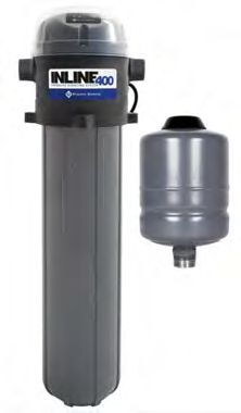
INSTALLATION
Inline 400 Mounting

Inline 400 Mounting

Orientation of the Inline 400
    It is preferred (for ease of priming) to install the Inline 400
    unit in a VERTICAL orientation.
    However, the unit can be installed in the HORIZONTAL
    position as long as the air-bleed valve is facing upwards
    (arrow) and the pump is laying horizontally. Never allow
    the pump to hang unsupported from a horizontal surface;
    never use the plumbing for pump support. Always use the
    mounting bracket for pump support.

8
INSTALLATION
Inline 400 Mounting
Flow Direction
In VERTICAL installations, the Inline 400 comes standard with the flow direction being from LEFT to RIGHT
when mounted vertically on a wall. In this orientation, you can view the status display and the label (1) is in
front.
The flow direction can be easily changed to RIGHT to LEFT by removing two pump 3
mounting bolts (2), rotating the pump 180 degrees, and re-installing the two
mounting bolts. There are four mounting lugs on the unit, so you can rotate the
pump in 90° increments (in relation to the mounting bracket) if desired.
It is possible to rotate the control cap. Remove six control cap screws (3) and rotate 1
the cap in 60 degree increments to place the status display in a viewable orienta-
tion.
2
NOTE: Be careful when rotating the control cap as there is an electrical cable
attached to it.
Plumbing Considerations for Priming Purposes
The Inline 400 needs to be primed with water before it can function properly. There is an internal check
valve built into the unit that needs to open during priming. This requires that the priming water has an
incoming pressure of 1.5 psi (0.1 bar) minimum. This is especially important if the application involves boost-
ing water out of a shallow cistern. There are two ways to accomplish this in the suction plumbing:
PRIMING DIAGRAM: 1.5 psi (0.1 bar) can be
achieved on the inlet by pouring water through a 3
feet (91 cm) vertical water column. Be sure to keep
the inlet valve closed and open the air-bleed valve 6 6
until all air is purged from unit. Close the air bleed 1
valve. 1 2
INSET PRIMING DIAGRAM: Adequate inlet pres-
sure/flow can be achieved on the inlet by connect-
ing a working garden hose to a fitting on the inlet 2
side of the pump and running water into the pump.
Be sure to keep the inlet valve closed, turn on the 7
garden hose water supply, and open the air-bleed
valve until all air is purged from unit. Close the air
bleed valve.
3
1. Shut off valve for priming 4
2. Priming Inlet line
3. Outlet line
4. Outlet valve
5
5. Air Bleed Valve (Vent)
6. Add water or connect garden hose (inset
image) here
7. Three feet (91 cm) minimum
9INSTALLATION
Typical Installation Diagram
Typical Installation Diagram
11 4 12 11
1
3 5
6
7 6 4
2
4 10 11 8 9
10
1. Water from source
2. Inline 400
3. Power Cord (No plug end on 50 Hz models)
4. Ball Valve
5. Pressure Tank (no further away than 5’ / 1.5 m from the pump)
6. Pressure Gauge
7. Inlet Pressure Reducing Valve (optional)
8. Outlet Pressure Reducing Valve (optional)
9. Pressure Relief Valve
10. Union Coupling
11. Pipe Tee
12. Check Valve
10INSTALLATION
Plumbing Installation
Plumbing Installation
1. Close all water supply valves necessary to turn off the incoming water supply. Carefully drain the exist-
ing plumbing system of all water. Make adjustments to existing plumbing to accommodate the addition
of the Inline 400 plumbing.
2. Install the Inline 400 in the desired location using mounting bracket and mounting screws, refer to
“Inline 400 Mounting” on page 8. Screws for mounting the bracket are not included with the product.
• For ease of service, leave a clearance of 20 inches (51 cm) below the pump for housing removal.
This can be reduced if the unit is installed with two plumbing unions shown as (10) in the “Typical
Installation Diagram” on page 10. This makes it easy to remove the entire pump from the system
for servicing.
3. Install inlet and outlet plumbing to the unit. The inlet and outlet of the Inline 400 are labeled with
“INLET” and “OUTLET” respectively. Using ball valves (4) in the system allows for a “service bypass” so
the typical household can still have incoming water if unit maintenance is required.
• Unions (10) should be installed on the suction and discharge ends of the Inline 400.
• Use of PTFE thread sealant tape is recommended over paste; do not over tighten.
• An internal check valve is provided on the discharge of the pump. This valve prevents back flow.
• If the optional bypass loop is used, a check valve (12) should also be installed in the bypass.
• Be sure to check all local plumbing codes to ensure that all requirements pertaining to back flow
prevention are met.
4. Install the bladder-type pressure tank (5) (maximum recommended size: 2 gallon/8 liter) downstream
from the pump. The tank should be located within 5 feet (1.5 m) of the pump discharge.
• There should be no control/check valve between the pressure tank and the Inline 400.
• The tank should be charged no greater than 2 psi (0.1 bar) below the outlet pressure switch set-
ting. Factory outlet pressure switch setting is 40 psi (2.8 bar), therefore maximum tank pre-charge
is 38 psi (2.6 bar) for factory settings.
• The tank pre-charge pressure shall never exceed 80 psi (5.5 bar).
5. Install a pressure gauge (6) on both the inlet and outlet pipes. These will be required in order to prop-
erly adjust the system, as well as aid in potential system troubleshooting.
6. If the incoming supply is above 40 psi (2.8 bar), a pressure reducing valve (7) may be installed on the
inlet.
7. The Inline 400 will boost a downstream pressure equal to 55 psi (3.8 bar) + incoming psi. If the discharge plumb-
ing, fixtures, and appliances are not rated for these higher pressures, it is recommended to install a pressure
reducing valve (8) after the pressure tank to limit the max downstream pressure.
8. Install a pressure relief valve (9) downstream of the Inline 400. This discharge must be plumbed to a
drain rated for maximum pump output at relief pressure settings.
11OPERATION
Electrical Installation
Electrical Installation
Risk of severe injury or death by electrical shock.
• Always disconnect the electrical power before working on or around the system.
• Check local electrical and building codes before installation. The installation must be in accordance
with their regulations as well as the most recent National Electrical Code (NEC).
• Some pumps are supplied with lead wires and are intended to be hardwired using a junction box or
other approved enclosure. The pumps include a grounding connector. To reduce risk of electric
shock, be certain that it is properly connected to ground.
• Some pumps are supplied with a grounding conductor and grounding-type attachment plug. To
reduce risk of electric shock, be certain that it is connected only to a properly grounded grounding-
type receptacle. Do not remove the third prong from the plug. The third prong is to ground the pump
to help prevent possible electric shock hazard.
Employ a licensed electrician to perform all wiring. All wiring must be done in accordance with applicable
national and local electrical codes.
1. Disconnect electrical power at the main breaker.
2. The pump should be wired to its own circuit, with no other outlets or equipment in the circuit.
3. Verify that the dedicated branch circuit for the Inline 400 is equipped with a 15 amp circuit breaker.
4. Check that the power supply corresponds with the electrical rating of the Inline 400 being installed.
Supply voltage must be ± 10% of the nameplate voltage.
5. Every installation must be grounded. There must be a reliable ground connection between the pump
and the main electric panel.
6. Unit should be plugged into an outlet that matches the voltage of the unit purchased, or wired directly
to a dedicated circuit junction box (for 50 Hz models, as they have no plug on the power cord).
OPERATION
Priming the System
Refer to “Plumbing Considerations for Priming Purposes” on page 9 for additional information.
Risk of bodily injury or property damage.
• The Inline 400 Pressure Boosting System can develop very high pressure in some situations.
• Always install a pressure relief valve able to pass full pump flow at 120 psi (6.9 bar). Install the pres-
sure relief valve near the pressure tank.
• It might be necessary to install a pressure reducing valve to limit the potential boost. Install the
pressure reducing valve after the pressure tank.
Prior to system start up, all air must be removed from the entire system. The Inline 400 comes with an air
bleed valve to assist with eliminating the air.
1. Close all system water outlets.
2. Using a small flathead screwdriver, slowly open the air bleed valve (located directly under the pump outlet).
3. Open inlet valves to allow water supply to enter the pump. Be prepared for air mixed with some water to
be discharged through the air bleed valve. It may be handy to have a small bucket to catch the water.
12OPERATION
Priming the System
4. When the air bleed valve stops sputtering and only a fine stream of water is being expelled, close the
air bleed valve.
5. Once the air has been evacuated from the pump, slightly open a system outlet valve. If necessary, start
the pump by pressing the pushbutton. This will put the pump into automatic mode.
6. Open a discharge valve to half open. If, after a few minutes of running, you do not get pressurized
water, repeat the priming process as detailed above.
NOTE: If the unit does not prime in 10 seconds, the pump will stop and the red LED light will flash, in a
one blink pattern on the display. This is due to an UNDERLOAD error condition in which the pump is not
yet incurring a load indicating water is being pumped. Simply press the pushbutton again to allow the
pump to run for an additional 10 seconds in order to attempt prime. REPEAT this as necessary.
7. Once the pump is operating, fully open the discharge valve and a system outlet, letting the pump oper-
ate until the water is running without any air sputtering.
No further priming should be needed unless the pump is drained, or a leak develops in the suction plumbing.
IMPORTANT: NEVER OPEN THE AIR BLEED WITH THE PUMP ON as this may allow air to ENTER the pump
rather than expel it from the system.
Adjusting Performance
When installed properly with an external pressure tank, it is possible to adjust the pump CUT-IN pressure of
the Inline 400 unit.
High voltages capable of causing severe injury or death by electrical
shock are present in this unit.
• Disconnect power to the system before attempting to remove the control cap and adjust the dis-
charge pressure switch.
The Inline 400 pump is factory-set to start boosting (turn pump ON) when the discharge pressure drops
below 40 psi (2.8 bar). In certain applications, it may be desirable to adjust this setting to be higher or
lower. See the example below:
In this example, a home is supplied with pressurized water from the local municipality that fluctuates
between 30 psi (2.1 bar) MAX and 25 psi (1.7 bar) MIN. The Inline 400 adds 55 psi (3.8 bar) to the incoming
water pressure.
MAX Total Downstream Pressure is 30 psi + 55 psi = 85 psi (2.1 bar + 3.8 bar = 5.9 bar)
MIN Total Downstream Pressure is 25 psi + 55 psi = 80 psi (1.7 bar + 3.8 bar = 5.5 bar)
This condition will result in a pressure drop from 80 or 85 psi down to 40 psi before the pump initially turns
ON (this DROP is due to the stored water being discharged from the pressure tank).
13OPERATION
Priming the System
If the installer desires to change this from a 80 psi–40 psi drop to a 80 psi–50 psi drop, the discharge pres-
sure switch can be adjusted to turn the pump ON when the discharge pressure reaches 50 psi.
Follow these steps:
1. Disconnect the unit from incoming power.
2. Remove the six control cap screws and remove the cap.
NOTE: Be careful when removing the control cap, as there is an electrical cable attached to the cap.
3. Using a 7/32" hex wrench, turn the internal discharge pressure switch screw (2) clockwise one full turn.
This should raise the switch cutoff by 10–12 psi (0.7 - 0.8 bar).
4. Replace the control cap and re-install six control cap
screws. 2
5. If desired (not required), adjust the pressure tank pre-
charge pressure to a maximum of 2 psi (0.1 bar) below
the new outlet pressure switch setting (48 psi (3.3 bar)
in this example).
NOTE: NEVER adjust the discharge pressure switch to a 1 3
setting HIGHER than the SUM of your minimum incom-
ing pressure + 40 psi, as doing so may result in a system
fault (flashing red LED).
1. Water Source INLET
2. Pressure Switch adjustment screw
3. Water OUTLET
Effect of System Leaks
Leaking water systems may cause the system to cycle more than expected. This is due to the unit turning on
when the outlet pressure drops below the preset discharge pressure (factory-set at 40 psi/2.8 bar). Contin-
uous running or a high number of starts and stops will not hurt the controller, pump, or motor. The issue
should still be fixed, if possible, to eliminate an increase in power usage of the system.
14OPERATION
Status Display
Status Display
The Inline 400 is designed to provide basic feedback regarding the systems current operational state. This
communication is transmitted via the products LED light, integrated into the control head module. The LED
can be seen flashing in a repetitive pattern representing operational state.
If the Inline 400 has detected a fault condition, the repetitive flashes can be counted to determine which
fault the unit is reporting as the cause. “Troubleshooting” on page 19 provides more information on the pos-
sible faults being reported via LED light flashes.
The Inline 400 is equipped with two LED lights to provide system status and diagnostic information.
1. Solid Green Light: Indicates system is powered and is turned ON, but not currently running. The green
solid light will only be present when no faults are active.
2. Flashing Green Light: Indicates the pump is powered, turned ON, and running. A rapid blinking green
light (two blinks per second, followed by one second off) indicates inlet water supply pressure is above
40 PSI. The unit remains on stand-by until the inlet pressure switch detects incoming water pressure
below the 40 PSI limit.
3. Solid Red Light: Indicates the control is powered but currently in the OFF mode. Pressing the button
will toggle the unit into the ON mode.
4. Flashing Red Light: Indicates a FAULT has occurred. The unit will automatically attempt to restart. If an
immediate restart is needed, the button can be pressed to force a reset if the fault is no longer present.
If the problem persists, a qualified water professional should be contacted. See Troubleshooting Guide
for further detail on various fault code LED flash indications.
5. Pushbutton: The pushbutton can be used to turn the unit on or off. When the unit is powered but in the
OFF mode (solid red light), a press of this button will turn the unit ON. If the unit is powered and in the
ON mode (solid green light), a press of the button will shut the unit OFF. The pushbutton can also be
used to force a reset after a fault.
15OPERATION
Protection Features
Protection Features
Maximum Inlet Pressure
The maximum internal pressure rating of the Inline 400 is 100 psi (6.9 bar). Therefore, the maximum inlet
pressure when added to the maximum Inline 400 pump pressure must not exceed 100 psi (6.9 bar). The
unit incorporates an internal pressure switch that will not allow the unit to turn ON if the inlet pressure
exceeds 40 psi (2.8 bar) either before or during desired operation. The LED display will show rapid green
flash, 2 blinks per second, followed by a 1 second pause.
Example: If you wish to use this booster in an application with 45 psi (3.1 bar) incoming, it is recommended
to install a pressure reducing valve (PRV) on the inlet side of the unit. The PRV would be used to maintain a
constant pressure below the cut-in pressure and could be used to limit the maximum pressure created.
Maximum Output Pressure
The Inline 400 will maintain a “NO-FLOW” system pressure equal to the incoming pressure (psi/bar) plus
the shut-off pressure from the pump operating curve. For example, if the input pressure is 38 psi (2.6 bar),
at shut off the system will boost an additional 55 psi (3.8 bar). This means ALL plumbing downstream of the
Inline 400 would be subject to maintaining 93 psi (38 psi + 55 psi) or 6.4 bar (2.6 bar + 3.8 bar). If this high
pressure is undesirable due to the condition and/or configuration of the existing plumbing or appliances,
installing a PRV on the discharge of the Inline 400 is recommended to limit the maximum distributed pres-
sure.
Maximum Operating Temperature
The Inline 400 is equipped with two temperature sensors. One is installed integral to the motor to protect
the motor windings. The other is installed in the control head and senses the internal temperature of the
water. In both cases, the unit will fault at a maximum temperature of 120 °F (49 °C) and turn back on when
the temperature drops below 95 °F (35 °C). A control head sensor trip is indicated by a 5 flash pattern, fol-
lowed by a 1 second pause. The Inline 400 Control Head cannot detect a trip of the internal pump’s motor
faulting from an overload.
16MAINTENANCE
Draining the System
MAINTENANCE
Risk of bodily injury, electric shock, or property damage.
• Disconnect power to the unit before attempting to perform maintenance functions.
• All maintenance functions should be performed by a qualified service professional.
Draining the System
Disconnecting the pump will not necessarily drain all other parts of the piping system. If there are any con-
cerns with the proper procedure or necessity of draining the suction plumbing, contact a water systems pro-
fessional. All Inline 400 systems, piping, and water tanks exposed to freezing weather should be drained
when freezing conditions are expected. There is a drain plug on the bottom of the unit that may be used to
drain the disabled (powered off) system. If there are any concerns with the proper procedure to drain the
system’s pressure tank, contact the tank manufacturer for assistance.
Cleaning the Flow Piston
1. Control Head
2. Phillips Head Screws
3. Flow Cap
4. O-ring
5. Flow Piston
The flow piston may
become clogged with
mineral deposits or
debris.
To clean the Flow Pis-
ton:
1. Disconnect the unit from incoming power.
2. The system may be under pressure. As such, close both the inlet and outlet valves and drain all pressur-
ized water from the system prior to performing maintenance on the flow switch (described above).
3. Remove the six Inline 400 cap screws and remove the cap.
NOTE: Be careful when removing the control cap, as there is an electrical cable attached to the head.
4. Remove the three Phillips screws that hold the flow cap in place.
5. Remove the Flow Cap. The O-ring may come off with the cap or may remain in the head. Remove the
O-ring and make sure it is free of debris. Place it back on the bottom of the Flow Cap.
6. Use a small metal object, such as a screwdriver or nut driver, to retrieve the magnetic Flow Piston from
the cavity (it is magnetic and will stick to the metal object).
7. Clean the Flow Piston with a clean cloth.
8. Clean any debris or residue from the head where the Flow Piston is inserted.
9. Replace the Flow Piston into the Control Head. Press the Flow Cap with the O-ring firmly into the head.
Tighten the three screws to 15 in-lbs (1.7 N-m). Do not over tighten.
10. Replace the Inline 400 cap and tighten six screws to 15 in-lbs (1.7 N-m).
11. Re-calibrate control head (see “Re-calibration of Control Head” on page 18).
17MAINTENANCE
Cleaning the Flow Piston
Re-calibration of Control Head
There are times, especially after servicing, that the Inline 400 needs to be re-calibrated. This is necessary in
order to re-establish a reference point for the indication of flow.
Follow these procedures for Field Flow Calibration:
1. Remove power from the unit by unplugging it or turning off the circuit breaker (if a 50 Hz direct wired
model).
2. Verify there is no water flowing in the system. This will ensure that the flow piston is in the fully seated
(zero flow) position.
3. While holding down the push button (3) on the status display, plug the 3
unit’s power cord into the power receptacle (or switch on the breaker, if a
50 Hz direct wired model). Continue holding down the button for five sec-
onds until both the green and red LEDs blink, indicating calibration is com-
plete. Release the button and the red LED should come on solid, indicating
calibration was successful.
4. Open valves/taps to begin water flow and confirm unit is operating properly.
18MAINTENANCE
Troubleshooting
Troubleshooting
The Inline 400 provides basic feedback regarding the system’s current operational state. The product’s LED
lights are integrated into the control head. Refer to “Status Display” on page 17. The LED flashes in a repeti-
tive pattern representing operational state. The repetitive flashes can be counted to determine which fault
the unit is reporting.
Observed Condition Indicator Lights Possible Cause Corrective Action
• Turn on the circuit breaker.
Unit will not turn on - No green or Circuit breaker tripped or
None • Consult a licensed electrician to properly wire the
red LED illuminated on control cap turned off
Outlet/Junction Box.
Flashing Green 10 sec- • Check water supply, valving, and priming sections
Unit runs briefly, won’t develop onds, then flashing Red Insufficient water or prime of this manual for additional information.
pressure, then turns off 1 flash,
1 second pause
Rapid Green flash, 2 Inlet water pressure above • Install a pressure reducing valve on inlet to reduce
Unit won’t start with demand for
blinks per second, inlet pressure, or wait for the inlet pressure to fall
water 1 second pause 40 psi (2.8 bar)
below 40 psi (2.8 bar).
Improper charge pressure • Set the pressure in pressure tank to 2 psi lower than
Unit continuously cycles ON/OFF in tank cut-in pressure.
Flashing Green
(Rapid Cycle) Check valve between tank • Place check valve after pressure tank.
and unit
Solid Red Unit is turned OFF • Press the push button on the user interface.
• Check inlet water supply and valving.
Flashing Red, 1 Flash, Dry Run Fault • Make sure outlet pressure switch setting is not
1 Second Pause
adjusted too high.
Overvoltage (input voltage • Consult a licensed electrician to check the supply
Flashing Red, higher than +10%) voltage and correct.
2 Flashes,
1 Second Pause Undervoltage (input volt- • Consult a licensed electrician to check the supply
age lower than -10%) voltage and correct.
Flashing Red, Flow Sensor Component • Consult professional for replacement parts or unit.
3 Flashes,
Unit won’t turn on 1 Second Pause Failure
Flashing Red, • Consult professional for replacement parts or unit.
4 Flashes, Temperature sensor fault
1 Second Pause
Flashing Red, Overheating due to exces- • Supply cold water to the pump.
5 Flashes,
1 Second Pause sive water temperature
Continuous hot water • Improper hot water application of unit. Supply cold
Flashing Red, detected above thermal water to the pump.
6 Flashes,
1 Second Pause limit when unit is not run-
ning
Leak or usage exceeds • Repair all plumbing leaks.
½ gpm(1.9 lpm) in system
plumbing
Internal non-return (check) • Place a new non-return (check) valve before Inline
Unit runs or cycles continuously Flashing Green
valve is blocked or dam- 400 unit in INLET plumbing.
aged
Internal flow piston is stuck • Clean the flow piston (see “Cleaning the Flow
open Piston” on page 17)
NOTE: The motor in this Inline 400 unit contains thermal protection that responds to motor current and heat from the motor winding and ambient
temperature. When the combination of current and heat exceeds a pre-determined point, the thermal protector opens and interrupts the circuit.
When the winding temperature returns to a more normal level, the thermal protector will automatically reset.
19STANDARD LIMITED WARRANTY
Except as set forth in an Extended Warranty, for one (1) year from the date of installation, but in no event more than two (2) years from the
date of manufacture, Franklin hereby warrants to the purchaser (“Purchaser”) of Franklin’s products that, for the applicable warranty period,
the products purchased will (i) be free from defects in workmanship and material at the time of shipment, (ii) perform consistently with sam-
ples previously supplied and (iii) conform to the specifications published or agreed to in writing between the purchaser and Franklin. This lim-
ited warranty extends only to products purchased directly from Franklin. If a product is purchased other than from a distributor or directly
from Franklin, such product must be installed by a Franklin Certified Installer for this limited warranty to apply. This limited warranty is not
assignable or transferable to any subsequent purchaser or user.
a. THIS LIMITED WARRANTY IS IN LIEU OF ALL OTHER WARRANTIES, WRITTEN OR ORAL, STATUTORY, EXPRESS, OR IMPLIED, INCLUDING
ANY WARRANTY OF MERCHANTABILITY OR FITNESS FOR A PARTICULAR PURPOSE. PURCHASER’S SOLE AND EXCLUSIVE REMEDY FOR
FRANKLIN’S BREACH OF ITS OBLIGATIONS HEREUNDER, INCLUDING BREACH OF ANY EXPRESS OR IMPLIED WARRANTY OR OTHER-
WISE, UNLESS PROVIDED ON THE FACE HEREOF OR IN A WRITTEN INSTRUMENT MADE PART OF THIS LIMITED WARRANTY, SHALL BE
FOR THE PURCHASE PRICE PAID TO FRANKLIN FOR THE NONCONFORMING OR DEFECTIVE PRODUCT OR FOR THE REPAIR OR REPLACE-
MENT OF NONCONFORMING OR DEFECTIVE PRODUCT, AT FRANKLIN’S ELECTION. ANY FRANKLIN PRODUCT WHICH FRANKLIN DETER-
MINES TO BE DEFECTIVE WITHIN THE WARRANTY PERIOD SHALL BE, AT FRANKLIN’S SOLE OPTION, REPAIRED, REPLACED, OR A
REFUND OF THE PURCHASE PRICE PAID. Some states do not allow limitations on how long an implied warranty lasts, therefore, the lim-
itations and exclusions relating to the products may not apply.
b. WITHOUT LIMITING THE GENERALITY OF THE EXCLUSIONS OF THIS LIMITED WARRANTY, FRANKLIN SHALL NOT BE LIABLE TO THE
PURCHASER OR ANY THIRD PARTY FOR ANY AND ALL (i) INCIDENTAL EXPENSES OR OTHER CHARGES, COSTS, EXPENSES (INCLUDING
COSTS OF INSPECTION, TESTING, STORAGE, OR TRANSPORTATION) OR (ii) DAMAGES, INCLUDING CONSEQUENTIAL, SPECIAL DAM-
AGES, PUNITIVE OR INDIRECT DAMAGES, INCLUDING, WITHOUT LIMITATION, LOST PROFITS, LOST TIME AND LOST BUSINESS OPPOR-
TUNITIES, REGARDLESS OF WHETHER FRANKLIN IS OR IS SHOWN TO BE AT FAULT, AND REGARDLESS OF WHETHER THERE IS OR
THERE IS SHOWN TO HAVE BEEN A DEFECT IN MATERIALS OR WORKMANSHIP, NEGLIGENCE IN MANUFACTURE OR DESIGN, OR A
FAILURE TO WARN.
c. Franklin’s liability arising out of the sale or delivery of its products, or their use, whether based upon warranty contract, negligence, or
otherwise, shall not in any case exceed the cost of repair or replacement of the product and, upon expiration of any applicable warranty
period, any and all such liability shall terminate.
d. Without limiting the generality of the exclusions of this limited warranty, Franklin does not warrant the adequacy of any specifications
provided directly or indirectly by a purchaser or that Franklin’s products will perform in accordance with such specifications. This limited
warranty does not apply to any products that have been subject to misuse (including use in a manner inconsistent with the design of the
product), abuse, neglect, accident or improper installation or maintenance, or to products that have been altered or repaired by any per-
son or entity other than Franklin or its authorized representatives.
e. Unless otherwise specified in an Extended Warranty authorized by Franklin for a specific product or product line, this limited warranty
does not apply to performance caused by abrasive materials, corrosion due to aggressive conditions, or improper voltage supply.
f. With respect to motors and pumps, the following conditions automatically void this limited warranty:
1. Mud or sand deposits which indicate that the motor has been submerged in mud or sand.
2. Physical damage as evidenced by bent shaft, broken or chipped castings, or broken or bent thrust parts.
3. Sand damage as indicated by abrasive wear of motor seals or splines.
4. Lightning damage (often referred to as high voltage surge damage).
5. Electrical failures due to the use of non-approved overload protection.
6. Unauthorized disassembly.
For technical assistance, please contact:
800.348.2420 | franklinwater.com
Form 106935101 Rev. 10 06/19ES ESPAÑOL
INLINE 400 SISTEMA DE PRESURIZACIÓN
Manual para propietarios
franklinagua.comINFORMACIÓN SOBRE PROPIEDAD INTELECTUAL
Franklin Electric
Publicaciones técnicas
9255 Coverdale Road
Fort Wayne, IN 46809
Copyright © 2019, Franklin Electric, Co., Inc. Todos los derechos están reservados.
La totalidad del contenido en esta publicación es material protegido por derechos de autor conf orme a las leyes estadounidenses y las
leyes de propiedad intelectual y las disposiciones de tratados de todo el mundo. Ninguna parte de este documento podrá ser copiado,
reproducido, distribuido, republicado, descargado, exhibido, publicado o transmitido en forma alguna a través de ningún medio, inclui-
dos medios electrónicos, mecánicos, fotocopias, grabaciones u otros, sin permiso previo y escrito de Franklin Electric. Usted puede des-
cargar una copia de la publicación desde www.franklinwater.com a una sola computadora con el solo fin de su uso interno personal y no
35TU U35T
comercial. Esta es una sola copia, una única licencia de uso, no una transferencia de pr opiedad, y está sujeta a las siguientes restric-
ciones: usted no puede modificar los documentos, usarlos con fines comerciales, exhibirlos en público ni quitarles cualquier aviso sobre
derechos de aut or o propiedad intelectual.
La información en esta publicación se brinda únicamente como referencia y está sujeta a cambios sin aviso previo. Pese a haber real-
izado todos los esfuerzos posibles por garantizar la precisión de este manual al momento de su publicación, las mejor as y las actual-
izaciones continuas del producto pueden volver obsoletas las copias. Consulte www.franklinwater.com para obtener la versión actual.
35TU U35T
Esta publicación se ofrece “tal como está”, sin garantías de ningún tipo, e xplícitas o implícitas. En la mayor medida posible conforme a
las leyes aplicables, Franklin Electric se desliga de toda garantía, explícita o implícita, incluidas entre otras las garantías implícitas de
comerciabilidad, adecuación a un uso particular y no violación de derechos de propiedad intelectual u otras violaciones de derechos.
Franklin Electric no garantiza ni efectúa declaraciones sobre el uso, la validez, la pr ecisión o la fiabilidad del material en esta publicación.
Bajo ninguna circunstancia, incluidos entre otros casos de negligencia, Franklin Electric será responsable por los daños directos, indirec-
tos, especiales, incidentales, resultantes u otros daños, incluidos, entre otros, pérdidas de datos, daños a las pr opiedades o gast os que
surjan o est én vinculados de algún modo a la instalación, funcionamiento, uso o mantenimiento del producto sobre la base del material
en este manual.
Marcas comerciales utilizadas en esta publicación:
Las marcas comerciales, las marcas de servicio y los logotipos que aparecen en esta publicación son marcas comerciales registradas y no
registradas de Franklin Electric y otros. Usted no recibió, en forma explícita, implícita, por impedimento u otro motivo , permiso o der
echo a usar cualquier marca comercial, mar ca de servicio o logotipo que aparece en este sitio, sin el permiso expreso por escrito de
Franklin Electric.
FE Logo y Design® y Inline 400™ son marcas comerciales registradas de Franklin Electric.
NEMA es una marca registrada de The Association of Electrical Equipment and Medical Imaging Manufacturers.
2TABLE OF CONTENTS
ÍNDICE
INSTRUCCIONES SOBRE SEGURIDAD - - - - - - - - - - - - - - - - - - - - - - - - - - - - - --- 4
INFORMACIÓN SOBRE EL PRODUCTO - - - - - - - - - - - - - - - - - - - - - - - - - - - - --- 5
Descripción - - - - - - - - - - - - - - - - - - - - - - - - - - - - - - - - - - - - - - - --- 5
Características - - - - - - - - - - - - - - - - - - - - - - - - - - - - - - - - - - - - - - --- 5
Modelos - - - - - - - - - - - - - - - - - - - - - - - - - - - - - - - - - - - - - - - - - --- 5
Componentes del Sistema - - - - - - - - - - - - - - - - - - - - - - - - - - - - - - - - --- 6
En la Caja - - - - - - - - - - - - - - - - - - - - - - - - - - - - - - - - - - - - - - - - --- 6
INSTALACIÓN - - - - - - - - - - - - - - - - - - - - - - - - - - - - - - - - - - - - - - - - --- 7
Requisitos Ambientales - - - - - - - - - - - - - - - - - - - - - - - - - - - - - - - - - --- 7
Consideraciones especiales para uso al aire libre - - - - - - - - - - - - - - - - - - - --- 7
Ubicación - - - - - - - - - - - - - - - - - - - - - - - - - - - - - - - - - - - - - - --- 7
Tanque de Presión- - - - - - - - - - - - - - - - - - - - - - - - - - - - - - - - - - --- 7
Montaje Inline 400 - - - - - - - - - - - - - - - - - - - - - - - - - - - - - - - - - - - - --- 8
Orientación para la Instalación del Inline 400 - - - - - - - - - - - - - - - - - - - - - --- 8
Dirección del Flujo - - - - - - - - - - - - - - - - - - - - - - - - - - - - - - - - - - --- 9
Consideraciones de la tubería para propósito del cebado - - - - - - - - - - - - - - - --- 9
Instalación típica - - - - - - - - - - - - - - - - - - - - - - - - - - - - - - - - - - - - - --- 10
Instalacion de Plomeria - - - - - - - - - - - - - - - - - - - - - - - - - - - - - - - - - --- 11
Instalacion electrica - - - - - - - - - - - - - - - - - - - - - - - - - - - - - - - - - - - --- 12
OPERACIÓN - - - - - - - - - - - - - - - - - - - - - - - - - - - - - - - - - - - - - - - - - --- 12
Cebado del sistema - - - - - - - - - - - - - - - - - - - - - - - - - - - - - - - - - - - --- 12
Ajuste de Rendimiento - - - - - - - - - - - - - - - - - - - - - - - - - - - - - - - --- 13
Efecto de las fugas del sistema - - - - - - - - - - - - - - - - - - - - - - - - - - - - --- 14
Pantalla de Estado - - - - - - - - - - - - - - - - - - - - - - - - - - - - - - - - - - - - --- 15
Rasgos de Protección - - - - - - - - - - - - - - - - - - - - - - - - - - - - - - - - - - --- 16
Presión máxima de entrada - - - - - - - - - - - - - - - - - - - - - - - - - - - - - --- 16
Presión máxima de salida - - - - - - - - - - - - - - - - - - - - - - - - - - - - - - --- 16
Temperatura máxima de funcionamiento - - - - - - - - - - - - - - - - - - - - - - - --- 16
MANTENIMIENTO - - - - - - - - - - - - - - - - - - - - - - - - - - - - - - - - - - - - - - --- 17
Drenaje del sistema - - - - - - - - - - - - - - - - - - - - - - - - - - - - - - - - - - - --- 17
Limpieza del interruptor de flujo - - - - - - - - - - - - - - - - - - - - - - - - - - - - - --- 17
Re-calibración de la cabeza de control - - - - - - - - - - - - - - - - - - - - - - - - --- 18
Solución de Problemas - - - - - - - - - - - - - - - - - - - - - - - - - - - - - - - - - - --- 19
GARANTÍA ESTÁNDAR LIMITADA- - - - - - - - - - - - - - - - - - - - - - - - - - - - - - - --- 20
3INSTRUCCIONES SOBRE SEGURIDAD
Mensajes de peligro
INSTRUCCIONES SOBRE SEGURIDAD
Mensajes de peligro
Este manual incluye precauciones de seguridad y otra informa- Esta unidad tiene voltajes elevados que
ción importante en los siguientes formatos: son capaces de provocar lesiones
graves o muerte por descarga eléctrica.
• Para reducir el riesgo de descarga eléctrica, desconecte la
Indica una situación inminentemente peligrosa energía antes de trabajar en el sistema o cerca de él. Es
que, de no evitarse, provocará una muerte posible que sea necesario más de un interruptor de
o lesiones graves. desconexión para cortar la energía del equipo antes de
realizarle un mantenimiento.
• Asegúrese de que esta bomba esté conectada a un circuito
Indica una situación potencialmente peligrosa equipado con un dispositivo interruptor de circuito por
que, de no evitarse, puede provocar una falla de conexión a tierra (GFIC).
muerte o lesiones graves. • Revise los tomacorrientes con un analizador de circuito
para garantizar que los cables de alimentación, neutro y a
tierra estén conectados correctamente. De lo contrario, un
electricista calificado y autorizado deberá rectificar el
Indica una situación potencialmente peligrosa problema.
que, de no evitarse, puede provocar lesiones • Cablee el sistema de bombeo para los voltajes correctos.
menores o moderadas.
Riesgo de lesiones corporales,
Indica una situación potencialmente peligrosa
descargas eléctricas o daños al
que, de no evitarse, puede provocar daños al
equipo.
equipo u otros bienes.
• Este equipo no deben usarlo niños ni personas con capaci-
IMPORTANTE: Identifica información que controla el ensam- dades físicas, sensoriales o mentales reducidas, ni aque-
blaje y el funcionamiento correctos del producto. llos que carezcan de experiencia y capacitación, salvo que
estén bajo supervisión o instrucción. Los niños no podrán
NOTA: Identifica información útil o aclaratoria. usar el equipo ni jugar con la unidad o en las cercanías
Este símbolo alerta al usuario sobre la presencia de un inmediatas.
voltaje peligroso dentro del producto que podría provo- • El equipo puede encenderse en forma automática. Realice
car lesiones o descargas eléctricas. los procedimientos de bloqueo/etiquetado antes de efec-
tuar el mantenimiento del equipo.
Este símbolo alerta al usuario sobre la presencia de • El funcionamiento de este equipo exige instrucciones
superficies calientes que podrían provocar incendios detalladas para su instalación y funcionamiento que se
o lesiones personales. encuentran en este manual para su uso con este producto.
• Lea la totalidad del manual antes de comenzar la insta-
Antes de empezar lación y el funcionamiento.
La instalación y el mantenimiento de este equipo deben estar • El usuario final debe recibir y conservar el manual para
a cargo de personal con capacitación técnica. El hecho de no usos futuros.
cumplir con los códigos eléctricos y de plomería nacionales • Mantenga las etiquetas de seguridad limpias y en buenas
y locales y con las recomendaciones de Franklin Electric puede condiciones.
provocar peligros de descarga eléctrica o incendio, desempeños • Mantenga el área de trabajo limpia, bien iluminada y orde-
insatisfactorios o fallas del equipo. nada.
Lea y siga las instrucciones cuidadosamente para evitar lesiones
y daños a los bienes. No desarme ni repare la unidad salvo que
esté descrito en este manual.
4INFORMACIÓN SOBRE EL PRODUCTO
Descripción
INFORMACIÓN SOBRE EL PRODUCTO
Descripción
Franklin Electric Inline 400 Sistema de Empuje de Presión proporciona el empuje de presión de echar agua conse-
cuente en aplicaciones comerciales residenciales y pequeñas que sufren de presión de marea baja o presión de echar
agua fluctuante a base de demanda. Cuando añadido al abastecimiento de agua existente, Inline 400 sentidos que
fluctúan la presión de echar agua, y automáticamente aumenta la presión de echar agua para mantener una presión de
echar agua constante en todas partes del sistema.
El 400 en línea está equipada con un sensor de flujo y dos interruptores de presión. Encenderá cuando el:
• La presión de descarga se cae abajo 40 psi (2.8 bar), o
• El flujo por el Inline 400 es ½ gpm (1.9 lpm) o mayor
El sistema Inline 400 deja de aumentar la presión cuando la demanda de agua cae por debajo del caudal de ½ galón
por minuto (1.9 lpm) (la bomba se apagará unos 15 segundos después de que se detenga el flujo). La unidad también
se puede apagar manualmente durante el funcionamiento normal presionando el botón en la tapa de la unidad.
El 400 en línea es fácil de instalar (montaje vertical u horizontalmente) mientras se trabaja con virtualmente
cualquier configuración de tuberías existentes.
NOTA: Las instalaciones horizontales se utilizan solo para uso en el INTERIOR. Las instalaciones verticales se
utilizan solo para uso en el EXTERIOR cuando se haya instalado la cubierta de protección transparente.
Características
Configuración
• Unidad conectada por cable eléctrico enchufable (solo modelos de 60 Hz)
• Se instala vertical u horizontalmente
• 1 ¼" NPT (BSPT para modelo de 50 Hz) Entrada y salida
• Incluye depósito de presión si se solicita como accesorio
• Temperatura máxima del agua de entrada: 120 °F / 49 °C
Funcionamiento
• Dos indicadores LED para el estado del sistema y la solución de problemas
• Los controles simples basados en el flujo aumentan la presión sobre la demanda
• Operación de fase sola
• Altura máxima de succión de 5 pies (1.5 m)
Protección
• Sobretensión (10% del valor nominal)
• Tensión insuficiente (-10% del valor nominal)
• Funcionamiento en seco (es decir, el motor está funcionando pero no se está
desarrollando presión o flujo)
• Sobrecalentamiento (más de 120 ° F temperatura del agua interna)
Modelos
Presurizac Sistema Flujo Peso
Modelo Voltaje Hz HP Corriente Potencia Fase ión Gabinete
Maxima máximo neto
máxima
55 psi 95 psi 20 gpm CSA
Inline 400 115 VAC 60 ⅓ 6.6 A 710 W 1 3.79 bar 6.55 bar 75 lpm Type 3
55 psi 95 psi 20 gpm CSA 35 lbs.
Inline 400 230 VAC 60 ⅓ 3.3 A 710 W 1 3.79 bar 6.55 bar 75 lpm Type 3 16 kg
220-230 50 psi 90 psi 16 gpm
Inline 400 50 Hz 50 ½ 2.7 A 630 W 1 IP24
VAC 3.45 bar 6.21 bar 60 lpm
5INFORMACIÓN SOBRE EL PRODUCTO
Componentes del Sistema
Componentes del Sistema
11
1
10
2
9
3
8
4
7
5
6
1. Tornillos de la tapa de la cabeza 2. Cable de alimentación (sin extremo de enchufe en
(6 en total) los modelos de 50 Hz)
3. Entrada 4. Base de montaje
5. Carcasa de la bomba 6. Tapón de drenaje de 1/4” NPT
7. Pernos de montaje (2 en total) 8. Válvula de purga de aire
9. Salida 10. Tapa de control
11. Pantalla de estado
En la Caja
1. Sistema de presurización Inline 400
2. Manual de instalación
3. Tanque de presión (accesorio si se pide e incluye con el Inline 400)
Todos los Sistemas de presurización Inline Franklin Electric son cuidadosamente probados, inspec-
cionados y empacados para asegurar que lleguen en condición perfecta. Cuando reciba la unidad,
examínela detenidamente para asegurarse de que no se hayan producido daños durante el envío.
Si hay daños evidentes, notifíquelos inmediatamente a la empresa transportista y al concesionario
del producto. La empresa transportista asume responsabilidad total por la llegada segura del
envío. Cualquier reclamo por daños al envío, ya sean visibles o encubiertos, debe hacerse primero
a través de la empresa transportista.
6You can also read