HIGH SPEED TWO PHASE 2a INFORMATION PAPER F2: PHASE 2a TUNNELS - Gov.uk
←
→
Page content transcription
If your browser does not render page correctly, please read the page content below
HIGH SPEED TWO
PHASE 2a INFORMATION PAPER

F2: PHASE 2a TUNNELS

    This paper outlines the range of proposed tunnelling methods to be deployed
    on the Proposed Scheme, the factors that influence the choice of method and
    the means of mitigating the construction and operational impacts associated
    with tunnelling.

    It will be of particular interest to those potentially affected by the Government’s
    proposals for high speed rail.

    This paper was prepared in relation to the promotion of the High Speed Rail
    (West Midlands-Crewe) Bill which is now enacted. It was finalised at Royal
    Assent and no further changes will be made.

    If you have any queries about this paper or about how it might apply to you,
    please contact the HS2 Helpdesk in the first instance.

    The Helpdesk can be contacted:

    by email:             HS2enquiries@hs2.org.uk

    by phone (24hrs):     08081 434 434
                          08081 456 472 (minicom)

    or by post:           High Speed Two (HS2) Limited
                          2 Snowhill, Queensway
                          Birmingham
                          B4 6GA

Version 1.2
Last updated: 11 February 2021

                                              1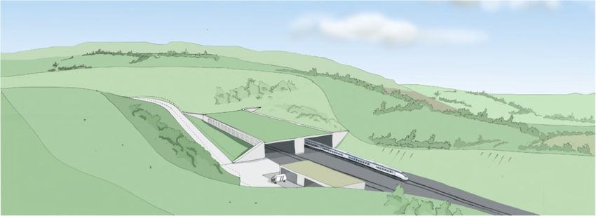
F2: PHASE 2a TUNNELS
    1. Introduction
    1.1.      High Speed Two (HS2) is the Government’s proposal for a new, high speed
              north-south railway. The proposal is being taken forward in phases: Phase One
              will connect London with Birmingham and the West Midlands. Phase 2a will
              extend the route to Crewe. Phase 2b will extend the route to Manchester, Leeds
              and beyond. The construction and operation of Phase One of HS2 is authorised
              by the High Speed Rail (London – West Midlands) Act 2017.
    1.2.      HS2 Ltd is the non-departmental public body responsible for developing and
              promoting these proposals. The company works to a Development Agreement
              made with the Secretary of State for Transport.
    1.3.      In July 2017, the Government introduced a hybrid Bill1 to Parliament to seek
              powers for the construction and operation of Phase 2a of HS2 (the Proposed
              Scheme). The Proposed Scheme is a railway starting at Fradley at its southern
              end. At the northern end it connects with the West Coast Main Line (WCML)
              south of Crewe to allow HS2 services to join the WCML and call at Crewe
              Station. North of this junction with the WCML, the Proposed Scheme continues
              to a tunnel portal south of Crewe.
    1.4.      The work to produce the Bill includes an Environmental Impact Assessment
              (EIA), the results of which are reported in an Environmental Statement (ES)
              submitted alongside the Bill. The Secretary of State has also published draft
              Environmental Minimum Requirements (EMRs)2, which set out the
              environmental and sustainability commitments that will be observed in the
              construction of the Proposed Scheme.
    1.5.      The Secretary of State for Transport is the Promoter of the Bill through
              Parliament. The Promoter will also appoint a body responsible for delivering the
              Proposed Scheme under the powers granted by the Bill. This body is known as
              the 'nominated undertaker'. The nominated undertaker will be bound by the
              obligations contained in the Bill and the policies established in the EMRs. There
              may be more than one nominated undertaker.
    1.6.     These information papers have been produced to explain the commitments
             made in the Bill and the EMRs and how they will be applied to the design and
             construction of the Proposed Scheme. They also provide information about the
             Proposed Scheme itself, the powers contained in the Bill and how particular
             decisions about the Proposed Scheme have been reached.

1 The High Speed Rail (West Midlands – Crewe) Bill, hereafter ‘the Bill’.
2 For more information on the EMRs, please see Information Paper E1: Control of Environmental Impacts.

                                                          2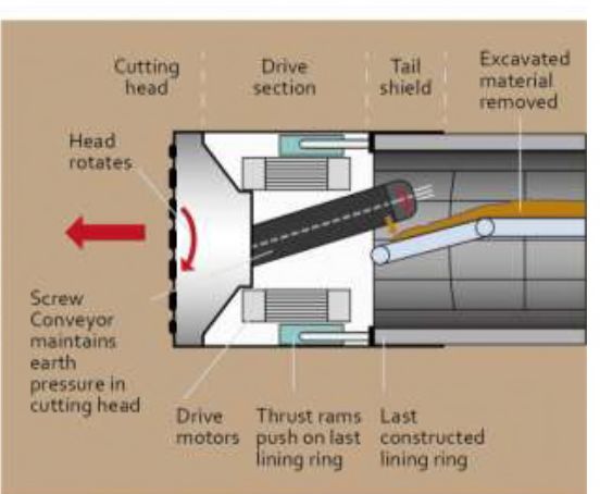
2. Overview
2.1 This paper provides an overview of the range of proposed tunnelling methods to
be employed on the Proposed Scheme and the means of mitigating the
construction and operational impacts associated with tunnelling.
2.1. Tunnelling is often necessary on railway lines where, due to the rolling nature of
the landscape, it would not be possible to align the track without steep inclines,
which are not compatible with railway operations. This is also the case for the
Proposed Scheme.
2.2. Tunnels have also been introduced into the Proposed Scheme for environmental
reasons, for example, to pass beneath built-up areas where disruption at the
surface would be severe.
3. Tunnels on Phase 2a
3.1. A brief overview of the types of tunnel planned for the Proposed Scheme is as
follows:
cut-and-cover tunnel (also referred to as green tunnel) – where a trench is
excavated and a concrete structure with a base, roof and walls is constructed
in the trench. Fill material and soil is then used to backfill the trench and
cover the top. The ground above is then restored and graded to blend it into
the surrounding landscape. A short length (about 200m) of the southern part
of the Whitmore Tunnel will be in cut-and-cover. See Figure 1 below for the
cross section of a typical cut-and-cover tunnel;
Figure 1: Cross section of a typical cut-and-cover tunnel
bored tunnels – where two parallel tunnels, each containing a single rail
track, are constructed. This can be done by either using tunnel boring
machines (TBMs) or by excavation of a single-bore tunnel with mechanical
3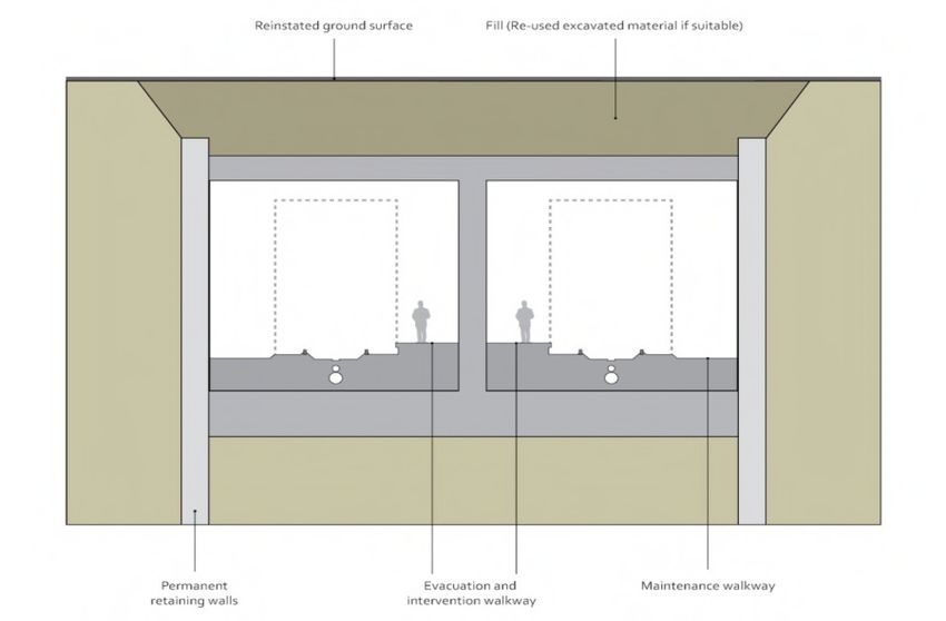
plant. The Proposed Scheme includes approximately 2km of twin-bore
tunnels (Whitmore and Madeley tunnels). These are planned to have an
internal diameter of 8.8m. See section 5 below for further information on
tunnel construction.
3.2. For safety reasons, when bored tunnels exceed 500m in length, they are
required to have cross passages to connect the two tunnel bores as well as
escape routes that run the full length of the tunnel and are connected to the
surface at tunnel portals. Cross passages and escape routes are required to
provide safe exit routes and emergency services access in the event of an
emergency. Figure 2 below for a typical cross-section of a twin-bored tunnel
with cross passage.
Figure 2: Cross section of a typical twin bore tunnel with cross passage escape route
3.3. On long tunnels, ventilation shafts may also be required at intermediate points
along the tunnel to provide further emergency service access and evacuation
points.
4. Tunnel Construction Methods
4.1. Bored tunnels are constructed either by starting from one entrance and
constructing the whole tunnel or by starting at both entrances and meeting in
the middle. The construction strategy will be to construct tunnels from the most
suitable entrance or entrances, based on:
distance from sensitive locations;
ease of access for logistics by road and rail;
impact on overall construction programme; and
economic use of plant and machinery.
4.2. At present, to construct the Whitmore and Madeley tunnels it is assumed that
Tunnel Boring Machines (TBMs) will be launched from the main tunnelling
4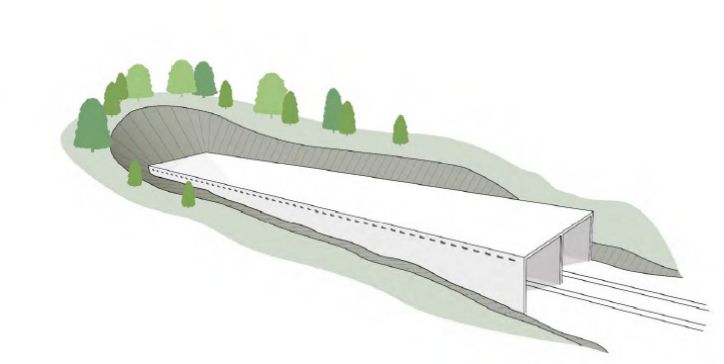
worksites at the southern portal of each tunnel. It is assumed that the tunnels
will be bored in a south to north direction.
4.3. The main tunnel worksites are required for the removal of excavated material
from the tunnel. They also form the main logistics area to take construction
material and operatives into the tunnel. Depending on the construction method,
the main worksite may also contain an area for casting concrete tunnel
segments.
4.4. Cut-and-cover tunnels are constructed either in an open excavation or in a
retained excavation.
4.5. The open excavation method involves excavating from the surface. Once the
final depth is reached the tunnel floor is constructed, followed by the walls and
roof to form a twin-cell box. Cut-and-cover tunnels in open excavation are
generally constructed in shorter bays. The bays gradually advance over the full
length of the tunnel section, with excavation being carried out from the ends of
each box section. On shorter lengths of cut-and-cover tunnel the full tunnel
length could be excavated at the same time.
4.6. The retained excavation method involves first constructing the walls using
diaphragm walling or bored piling, followed by excavation and construction of
the roof. Excavation of the tunnel is then undertaken beneath the roof slab from
the open ends of the box. This method is likely to be adopted where space
limitations restrict the width of an open excavation with side slopes.
5. Tunnel boring machines
5.1. HS2 Ltd has put together a high performance TBM specification that is
specifically designed to limit both tunnel construction risk and ground
movements to a practical minimum. The TBMs used to construct HS2 will be
purpose-built machines, using proven state-of-the-art technology and will
operate 24 hours a day, seven days a week. They will be designed specifically for
the project to ensure their reliability of performance, settlement control and to
cope with the range of ground conditions expected along the Proposed Scheme.
5.2. During the Jubilee Line extension, HS1 and Crossrail projects, bored tunnels
were driven successfully through ground conditions that would once have been
considered extremely difficult, and similar to the ground conditions on some of
the HS2 tunnels, proving the capability of modern construction techniques.
5.3. There are several types of TBM that employ different methods of supporting the
tunnel face during excavation depending on the ground conditions, but they all
involve essentially similar construction operations in terms of logistics.
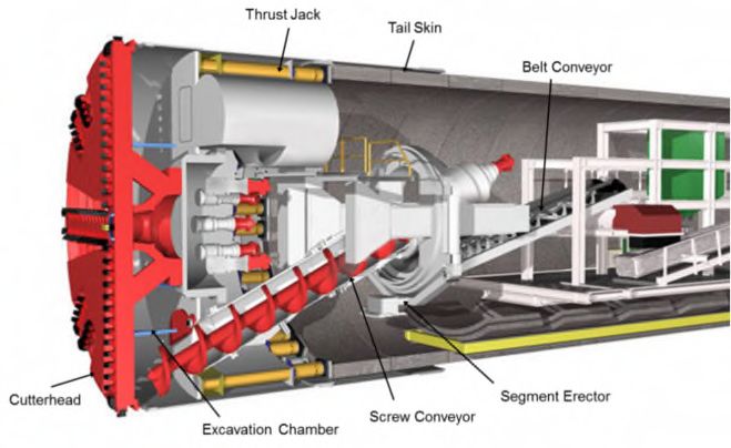
5.4. The TBMs most likely to be used on the Whitmore and Madeley tunnels are
Earth Pressure Balance Machines as shown in Figure 3 below.
5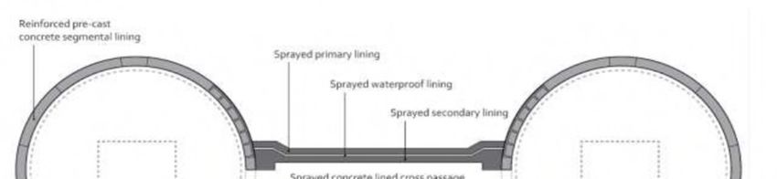
Figure 3: Earth Pressure Balance TBM
5.5. To ensure the TBMs are operating safely, information will be relayed to a
dedicated monitoring room manned by suitably experienced engineers. The
monitoring room will have displays of real-time surface, subsurface and tunnel
movements, together with TBM tunnel progress and TBM parameters.
5.6. This will ensure that the tunnel construction is being carried out to specification
and that ground movements and temporary vibration effects remain within
acceptable limits.
6. TBM operation
6.1. The TBMs will weigh over 1,000 tonnes when fully operational. They will be
delivered in smaller components and assembled near the tunnel entrance.
6.2. Where sufficient space is available, the TBM will be fully assembled before
launch, with all back-up equipment installed. Otherwise, the TBM will be
advanced and a sufficient length of tunnel constructed to allow the back-up
equipment to be assembled in the tunnel.
6.3. Where necessary, ground treatment will be carried out around the TBM launch
chamber structure to allow the TBM to be buried safely. This will also allow the
full stabilising effects of the TBM to be brought into operation.
6.4. Once the TBM is launched, the following tunnel construction cycle will begin:
excavation will be undertaken one tunnel lining ring3 at a time. First the TBM
will excavate a short section of tunnel. Next, the tunnel lining ring segments will
be built within the tail-skin of the TBM using a mechanical erector to form a
complete ring. Following this the next short section of tunnel will be excavated,
with the TBM propelled forwards by hydraulic jacks shoving off the previously
erected tunnel lining ring; Figure 4 below shows the layout in a typical TBM.
3 The tunnel will be built progressively through the building of joined ‘rings’ approximately 1.5m in length.
6
Figure 4: Sectional View of TBM Copyright Herrenknecht
grouting of the tunnel lining rings will be undertaken as a continuous process
through the tail-skin of the TBM to fill the voids between the tunnel lining rings
and the excavated surface of the ground behind;
materials (such as tunnel lining rings and grouts) will be delivered to the TBMs
by a narrow-gauge construction railway or other system such as pumping from
the surface; and
excavated materials may be removed by railway, specially designed rubber tyre
vehicles, conveyors or pumping, depending on the type of TBM and the length
of the tunnel.
6.5. TBM parameters will be monitored continuously both underground and within a
dedicated tunnel monitoring control room. An excavation/grout check will be
carried out to ensure all voids have been filled to minimise the risk of settlement.
6.6. The tunnelling operation will be continuous, which will minimise ground
movements. On completion of the tunnel drives, the TBMs will be dismantled
and removed from the tunnels.
7. Tunnelling Construction Phase Impacts
7.1. Noise and vibration due to tunnel boring during construction have been
assessed based on previous experience at the Dublin Port Tunnel, the Jubilee
Line Extension, HS1 and Crossrail. In general, the levels are low and occur for a
limited period only.
7.2. As with any underground works, ground movements affecting buildings could
occur during tunnel excavation or shortly thereafter. While the vast majority of
tunnelling projects are successful, with very low recorded ground settlements,
occasionally an incident occurs that results in higher localised ground
settlements or subsidence.
77.3. The impact of ground movements on buildings will be assessed through a well-
established three-stage process to determine whether there is a risk of potential
building damage. This process has been used successfully on both HS1 and
Crossrail. Full details of this process are set out in Information Paper C14:
Ground Settlement.
7.4. The environmental impacts of tunnelling are considered within the ES.
8. Tunnelling Operational Phase Impacts
8.1. Modern tunnelling methods mean the impact of ground-borne noise and
vibration from railway operations are relatively low and may be effectively
controlled. The main reasons for this are:
better quality track;
straighter track alignments;
smoother running surfaces on the rails;
fewer rail joints and the use of continuously welded track (reducing the
dynamic loads and consequently the wear and tear on the rolling stock); and
better suspension on the trains (which improves passenger comfort, as well
as reducing the impact forces on the track).
8.2. For high speed trains, the need for better performance requires that the track is
maintained to a very high standard. The process of calculating noise and
vibration from rail tunnels is well understood and the effects can be accurately
predicted. Where noise and vibration levels are considered to be an issue, well-
tried mitigation measures are available.
8.3. Recent projects, such as the Jubilee Line Extension and HS1 tunnels under
London, have shown that modern railways can run in tunnels under large
residential areas without noise and vibration affecting the people who live there
or disturbing other highly sensitive non-residential uses.
8.4. Further information on noise and vibration control, and mitigation is available in
Information Papers: E10 Control of ground-borne noise and vibration from the
operation of temporary and permanent railways; E11 Control of noise from the
operation of stationary systems; and E13 Control of construction noise and
vibration.
9. Tunnel lining design
9.1. Tunnel linings are required to;
structurally retain the earth and water pressure; and
provide an internal space appropriate to the function of the operational
railway.
89.2. Tunnel linings will be designed in accordance with the relevant regulatory
standards, guidelines and current practice. These are based on proven design
and construction technology that has been used successfully worldwide.
9.3. The linings will be designed to withstand all foreseeable loading, including
construction loads and those from the surrounding ground and groundwater.
They will also meet fire resistance and durability requirements.
9.4. As well as the train itself, the internal diameters of the tunnels have been sized
to accommodate the swaying movement of trains, the overhead power supply,
evacuation and access walkways, track slab, cables and associated furniture, and
construction tolerances. Their sizing also takes account of the aerodynamic
requirements of high speed trains.
9.5. The majority of the bored tunnels will be lined with pre-cast concrete tunnel
lining segments, reinforced with steel fibres and polypropylene fibres. To enable
connection between the twin bored tunnels, at intervals along the length of the
route, cross-passages will be constructed and the openings for these formed
using round graphite iron linings or steel frames encased in concrete alongside
precast concrete tunnel linings. The linings are made up of a number of tunnel
segments which are joined to form a ring.
9.6. The mined and cross passage tunnels, which are lined with sprayed concrete, will
have a primary sprayed lining of fibre-reinforced concrete with a waterproof
layer. A secondary lining of fibre-reinforced concrete will be either sprayed or
cast in place. These construction techniques have been used successfully on the
Crossrail project.
9.7. The lining of cut-and-cover tunnels will be conventional reinforced concrete.
10. Tunnel Porous Portals
10.1. A tunnel portal is the entry or exit section of a tunnel.
10.2. On high speed railways, the purpose of a porous portal at the entry of a tunnel is
to ensure that the micro pressure waves produced by the 'piston effect' of the
train moving through the tunnel, which can otherwise result in noise as the train
exits the tunnel, are controlled and kept at a level which does not adversely
affect the surrounding area.
10.3. A 'porous portal' is generally achieved by providing perforated structures,
usually of concrete, at the tunnel portal. These structures have openings of
increasing diameter, open to the outside air, running along their length.
10.4. Figure 5 and 6 below illustrate how porous portals on the Proposed Scheme
could look:
9Figure 5: Example of porous portal (1)
Figure 6: Example of porous portal (2)
11. Fit-Out of Tunnels
11.1. Once tunnels are excavated, lined and cleaned out, the following activities take
place:
construction of walkways and drainage;
installation of rail track and formation;
installation of mechanical and electrical systems; and
testing and commissioning.
1012. More information
12.1. More detail on the Bill and related documents can be found at: www.gov.uk/Hs2
11You can also read