HIGHLY EFFICIENT BLUE GREEN QUANTUM DOT LIGHT-EMITTING DIODES USING STABLE LOW-CADMIUM QUATERNARY-ALLOY ZNCDSSE/ZNS CORE/ SHELL NANOCRYSTALS
←
→
Page content transcription
If your browser does not render page correctly, please read the page content below
Research Article

                                                                                                                                                 www.acsami.org

Highly Efficient Blue−Green Quantum Dot Light-Emitting Diodes
Using Stable Low-Cadmium Quaternary-Alloy ZnCdSSe/ZnS Core/
Shell Nanocrystals
Huaibin Shen,†,§ Sheng Wang,†,§ Hongzhe Wang,† Jinzhong Niu,† Lei Qian,† Yixing Yang,‡
Alexandre Titov,‡ Jake Hyvonen,‡ Ying Zheng,*,‡ and Lin Song Li*,†
†
 Key Laboratory for Special Functional Materials, Henan University, Kaifeng 475004, P. R. China
‡
 NanoPhotonica Inc., 747 SW Second Avenue, Gainesville, Florida 32601, United States
    *
    S Supporting Information

    ABSTRACT: High-quality blue−green emitting
    ZnxCd1−xS1−ySey/ZnS core/shell quantum dots (QDs) have
    been synthesized by a phosphine-free method. The quantum
    yields of as-synthesized ZnxCd1−xS1−ySey/ZnS core/shell QDs
    can reach 50−75% with emissions between 450 and 550 nm.
    The emissions of such core/shell QDs are not susceptible to
    ligand loss through the photostability test. Blue-green light-
    emitting diodes (LEDs) based on the low-cadmium
    ZnxCd1−xS1−ySey/ZnS core/shell QDs have been successfully
    demonstrated. Composite films of poly[9,9-dioctylfluorene-co-
    N-[4-(3-methylpropyl)]-diphenylamine] (TFB) and ZnO
    nanoparticle layers were chosen as the hole-transporting and
    the electron-transporting layers, respectively. Highly bright blue−green QD-based light-emitting devices (QD-LEDs) showing
    maximum luminance up to 10000 cd/m2, in particular, the blue QD-LEDs show an unprecedentedly high brightness over 4700
    cd/m2 and peak external quantum efficiency (EQE) of 0.8%, which is the highest value ever reported. These results signify a
    remarkable progress in QD-LEDs and offer a practicable platform for the realization of QD-based blue−green display and
    lighting.
    KEYWORDS: ZnCdSSe/ZnS, alloy, core/shell, blue−green, QD-LEDs, electroluminescence

■    INTRODUCTION
Semiconductor quantum dots (QDs) show great promise for
                                                                                enhancement processes. Those alloyed QDs are high potential
                                                                                materials for stable and high performance blue emitters which
use in QD-based light-emitting devices (QD-LEDs), displays,                     may surpass the drawbacks of binary QD emitters.
and other photoelectric devices owing to their unique optical                      In this paper, we have prepared high-quality blue−green
properties.1−17 It is well-known that the tuning of photo-                      emitting quaternary ZnCdSSe QDs, which adjusted the optical
luminescence (PL) emission is accessible through altering the                   performance by not only the radio between Zn and Cd but also
size of the particles for binary II−VI QDs such as CdS and                      the radio between Se and S and the PL QYs could reach up to
CdSe which have been most intensively investigated.18                           40%. To improve the QY and stability of ZnCdSSe QDs, high-
However, these binary QD systems are still not very easy to                     quality blue−green emitting low-cadium ZnCdSSe/ZnS core/
deliver high quantum yield (QY) and stable blue−green                           shell QDs have been synthesized by a phosphine-free method.
emission between 450 and 530 nm due to the unstable fine                         The QYs of as-synthesized ZnCdSSe/ZnS core/shell QDs can
particles are difficult to passivate by overcoating shells.                       reach 50−75% with emissions between 450 and 550 nm. We
However, the wavelength at 450 and 530 nm are of particular                     also demonstrated blue−green light-emitting diodes based on
interest for the preparation of QD-based blue−green LEDs and                    the ZnCdSSe/ZnS core/shell QDs. The highly bright blue−
as “must-have” emitters for next-generation displays and white                  green QD-LEDs show a peak luminance up to 10000 cd/m2. In
solid-state lighting. Therefore, it is still very important to exploit          particular, the blue QD-LEDs show unprecedentedly high
new synthesis methods since the efficient and controllable                        brightness over 4700 cd/m2, which is the highest value ever
synthesis of high quality blue−green QDs is still a challenging                 reported and indicates the ZnCdSSe/ZnS core/shell QDs are
topic. Recently, alloyed Zn1−xCdx based chalcogenide QDs                        more suitable for making blue QD-LEDs. These results provide
(such as Zn1−xCdxS, Zn1−xCdxSe and ZnxCd1−xSySe1−y)19−25
have arisen as attractive candidates because their composition                  Received: January 31, 2013
sensitive emissions can be easily tuned to cover the whole                      Accepted: April 30, 2013
visible range and high operability for subsequent stability                     Published: April 30, 2013

                               © 2013 American Chemical Society          4260             dx.doi.org/10.1021/am400433y | ACS Appl. Mater. Interfaces 2013, 5, 4260−4265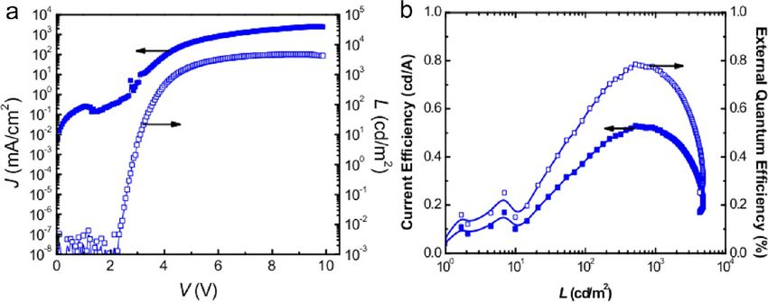
ACS Applied Materials & Interfaces                                                                                                                  Research Article

reliable conveniences for the realization of QD-based full color                   (DMSO) (0.5 M) and 30 mL of a solution of TMAH in ethanol (0.55
displays and lighting devices.                                                     M) were mixed and stirred for 1 h in ambient air, then washed and
                                                                                   dispersed in ethanol at a concentration of ∼30 mg mL−1. QD-LEDs

■   EXPERIMENTAL DETAILS
   Chemicals. All reagents were used as received without further
                                                                                   were fabricated on glass substrates coated with ITO with a sheet
                                                                                   resistance of ∼20 Ω sq−1. The substrates were cleaned with deionized
                                                                                   water, acetone, and isopropanol, consecutively, for 15 min each, and
experimental purification. Zinc oxide (ZnO, 99.99% powder),                         then treated for 15 min with ozone generated by ultraviolet light in air.
cadmium oxide (CdO, 99.99%, powder), sulfur (S, 99.98%, powder),                   These substrates were spin-coated with PEDOT:PSS (AI 4083) and
1-octadecene (ODE, 90%), oleic acid (OA, 90%), decanoic acid                       baked at 150 °C for 15 min in air. The coated substrates were then
(99%), and selenium (Se, 99.99%, powder) were purchased from                       transferred to a N2-filled glovebox for spin-coating of the poly[9,9-
Aldrich. Hexanes (analytical grade), paraffin oil (analytical grade), and            dioctylfluorene-co-N-[4-(3-methylpropyl)]-diphenylamine] (TFB),
methanol (analytical grade) were obtained from Beijing Chemical                    Zn1−xCdxS1−ySey/ZnS QD, and ZnO nanoparticle layers. The TFB
Reagent Ltd., China.                                                               hole-transport layer was spin-coated using 1.5 wt % in chlorobenzene
   Preparation of precursors. Stock Solution for Zn−Cd Precursor.                  (2000 rpm for 30 s), followed by baking at 110 °C for 30 min. This
A mixture (30 mL in total) of CdO (0.5760 g, 4.5 mmol) and ZnO                     was followed by spin-coating of Zn1−xCdxS1−ySey/ZnS QDs (10 mg
(0.3645 g, 4.5 mmol), oleic acid (27 mmol, 9 mL), and 21 mL paraffin                 mL−1, toluene) and ZnO nanoparticles (30 mg mL−1, ethanol) layers
oil was loaded in a 50 mL three-neck flask and heated to 260 °C under               followed by baking at 145 °C for 30 min. The spin speed is 1000 rpm
nitrogen to obtain a colorless clear solution. The resulting solution was          for the QD layer and 4000 rpm for the ZnO nanoparticle layer to
allowed to cool down to 100 °C for injection.                                      achieve layer thickness of ∼20 and ∼25 nm, respectively. These
   Stock Solution for Zn Precursor. A mixture (30 mL in total) of                  multilayer samples were then loaded into a custom high-vacuum
ZnO (0.2441 g, 3 mmol), oleic acid (25 mmol, 8 mL), and 22 mL                      deposition chamber (background pressure, ∼3 × 10⁻⁷ Torr) to
paraffin oil was loaded in a 50 mL three-neck flask and heated to 310                 deposit the top Al cathode (100 nm thick) patterned by an in situ
°C under nitrogen to obtain a colorless clear solution. The resulting              shadow mask to form an active device area of 4 mm2.
solution was allowed to cool down to 130 °C for shell growth.                         Characterization. Room temperature UV−vis absorption and PL
   Stock Solution for S Precursor. The sulfur precursor solution (0.1              spectra were measured with an Ocean Optics spectrophotometer
M) was prepared by dissolving sulfur (0.064 g, 2 mmol) in ODE (20                  (mode PC2000-ISA). PL quantum yields (QYs) were determined by
mL) at 150 °C.                                                                     comparison of the integrated fluorescence intensity of the QD samples
   Synthesis of Zn0.5Cd0.5S0.25Se0.75 QD. QDs with various ratios of               in solution with that of standard of known QYs (LD 423, QY = 68% in
Zn to Cd and S to Se have been synthetized. The Zn0.5Cd0.5S0.25Se0.75              ethanol; coumarin 540, QY = 78% in ethanol). All QYs data of QDs
QD was used as an example. A 0.1 mmol portion of S and 0.3 mmol of                 and dyes were collected through Ocean Optics USB2000 spectrometer
Se were mixed with 15 mL paraffin liquid, degassed for 30 min, filled                 and an Ocean Optics ISP-50-8-I integrating sphere. The optical
with N2, and heated to 310 °C. At this temperature, 3 mL of Zn0.5Cd0.5             density (OD) values of the QD samples and organic dyes at the
precursor solution was quickly injected to the flask containing the                 excitation wavelength were set the same in the range of 0.02−0.05. X-
above mixture. The new mixture was then maintained at 260 °C under                 ray diffraction (XRD) studies of NCs were carried out with a Philips
continuous stirring. Aliquots were taken at different time intervals such           X′ Pert Pro X-ray diffractometer using Cu−Ka radiation (λ = 1.54 Å).
as 10 s, 1 min, 5 min, and 30 min, respectively. The as-synthesized                Transmission electron microscopy (TEM) studies were performed
QDs were purified by repeated precipitation with methanol and                       using a JEOL JEM-2010 electron microscope operating at 200 kV.
redispersed in hexanes for several times. Other types of                           Current−luminance−voltage characteristics were measured using an
Zn1−xCdxS1−ySey QDs were prepared and purified following the                        Agilent 4155C semiconductor parameter analyzer with a calibrated
same procedures as described above for Zn0.5Cd0.5S0.25Se0.75 QDs. The              Newport silicon diode. The luminance was calibrated using a Minolta
ratio of S to Se and Zn to Cd varied from 7:1 to 1:7 and 8:1 to 1:8,               luminance meter (LS-100). The electroluminescence spectra were
respectively.                                                                      obtained with an Ocean Optics high-resolution spectrometer
   Synthesis of Zn1−xCdxS1−ySey/ZnS Core/Shell QDs with                            (HR4000) and a Keithley 2400 power source.

                                                                                   ■
Blue−Green Emission. It is well-known that the lattice mismatch
between the core and shell seriously limits the PL intensity. One                       RESULTS AND DISCUSSION
solution is to use a core and multishell structure such as CdSe/CdS/
CdZnS/ZnS.26 But this route is complex because of too many                         The composition-dependent PL and absorption spectra of
precursors. The lattice mismatch between the Zn1−xCdxS1−ySey core                  Zn0.5Cd0.5S1−ySey core QDs (Figure 1) were used for
and ZnS shell is relatively small so that this core/shell NCs structure            representing the spectra of the various composition ratios of
not only simplifies the synthesis process but also improves the QYs.                Zn1−xCdxS1−ySey core QDs. Zn0.5Cd0.5S1−ySey QDs recorded in
The growth of ZnS shells was performed by the method reported                      the composition of the molar ratio of S and Se range from 9: 1
previously.27 A typical synthesis was performed as follows: 4 mL of                to 1:9, and the PL peak shifts from 460, 474, 486, and 512 to
ODE and 3 g of ODA were loaded into a 100 mL reaction vessel. The                  538 nm, respectively. The photoluminescence of
purified Zn1−xCdxS1−ySey QDs in hexanes (3.5 nm in diameter, 3 ×
                                                                                   Zn0.5Cd0.5S1−ySey QDs redshift with the increase of the amount
10−7 mol) were added, and the system was kept at 100 °C under N2-
flow for 30 min to remove the hexanes and other undesired materials                 of Se due to the narrower band gap of Zn0.5Cd0.5Se than of
of low vapor pressure. Subsequently, the solution was heated up to 300             Zn0.5Cd0.5S. Powder X-ray diffraction (XRD) patterns of the
°C under N2-flow where the shell growth was performed. This is                      typical Zn0.5Cd0.5S1−ySey core QDs (Supporting Information
followed by alternating addition of Zn precursor and S-ODE                         Figure S1) reveal that they all have a zinc blende cubic crystal
precursor, respectively, and the amount of which were calculated                   structure. The diffraction peaks were apparently located
from the respective volumes of concentric spherical shells with a                  between those of the bulk CdSe and ZnS composites and
thickness of one hypothetical monolayer. An interval of 20 min was set             gradually shifted toward smaller angles as the S:Se molar ratio
for the growth of S layers and an interval of 30 min was set for the               changed from 9:1 to 1:9, indicating increased lattice constants
growth of Zn layers. Finally, a small amount of hexanes was added into
                                                                                   of the QDs with gradual substitution of S atoms with the bigger
the QDs solution and the unreacted compounds and byproducts were
removed by successive methanol extraction (at least three times).                  and heavier Se atoms, which is in accordance with Vegard’s
   Fabrication and Characterization of QD-LED. ZnO nano-                           law.28,29 Furthermore, by adjusting the relative amounts of the
particles were synthesized by a solution-precipitation process using Zn            four elements, the band gaps of the ZnCdSSe QDs can be
acetate and tetramethylammonium hydroxide (TMAH).11 For a                          continuously tuned from 450 to 550 nm. Figure 1b shows PL
typical synthesis, a solution of zinc acetate in dimethyl sulphoxide               data for a series of ZnCdSSe QDs with PL peaks at 460
                                                                            4261               dx.doi.org/10.1021/am400433y | ACS Appl. Mater. Interfaces 2013, 5, 4260−4265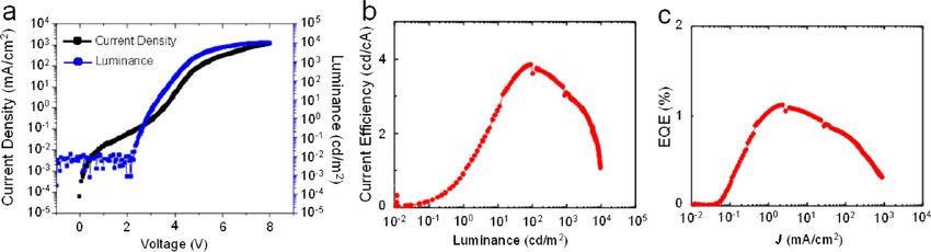
ACS Applied Materials & Interfaces                                                                                                              Research Article

                                                                                wave function leaking out into the shell material.30 During the
                                                                                subsequent shell growth, the absorption and PL-spectra slightly
                                                                                shifted to the blue, which was observed by Xie and co-
                                                                                workers,31 who discovered that the blue-shift was only
                                                                                happened when the particles are covered with additional ZnS.
                                                                                This phenomenon was ascribed to the fact that the Zn-atoms
                                                                                diffuse into the Cd-rich regions of the shell at high temperature,
                                                                                thus increasing the band-offset of the shell and hence the
                                                                                effective confinement.31,32 With the shell growth, the fwhm
                                                                                (full width at half-maximum) increases from 29 to 39 nm. To
                                                                                prove the high stability of as-synthesized Zn0.5Cd0.5S0.25Se0.75/
                                                                                ZnS core/shell QDs, ligand loss tests were adopted. It is clearly
                                                                                shown that the QYs of core−shell QDs do not show any
                                                                                decline upon many times of precipitation and redispersion in
                                                                                hexanes (Supporting Information Figure S2).
Figure 1. (a) Absorption and photoluminescence spectra of                          To further characterize the evolution of structures of
Zn0.5Cd0.5S1−ySey QDs with a constant Zn:Cd molar ratios of 1:1                 Zn0.5Cd0.5S0.25Se0.75/ZnS core/shell QDs, we also verified the
along with different S:Se molar ratios for 9:1, 3:1, 1:1, 1:3, and 1:9,          crystallographic properties by XRD (Figure 3). The XRD
respectively. (b) Composition-dependent band-edge emission of
ZnCdSSe QDs. (1) Zn:Cd:S:Se = 9:1:9:1; (2) Zn:Cd:S:Se =
4:1:4:1; (3) Zn:Cd:S:Se = 7:3:6:4; (4) Zn:Cd:S:Se = 3:2:2:3; and
(5) Zn:Cd:S:Se = 1:2:1:2.

(9:1:9:1), 474 (4:1:4:1), 486 (7:3:6:4), 512 (3:2:2:3), and 550
nm (1:2:1:2), respectively.
   It is well-known that ZnS is the most widely used shell
material for core/shell structures, because its relatively wide
band gap can effectively confine both the electrons and the
holes to the core region and thus improve the PL QYs and
stability.24 Figure 2 shows the absorption and PL spectra of the

                                                                                Figure 3. Powder XRD patterns of Zn0.5Cd0.5S0.25Se0.75 cores and
                                                                                core/shell QDs with different monolayers (MLs) of ZnS shell. For
                                                                                comparison, the standard powder diffraction patterns of cubic CdSe
                                                                                and ZnS bulk crystals are provided.

                                                                                patterns of bulk cubic CdSe and ZnS are shown at the bottom
                                                                                and top of Figure 3, respectively. The XRD pattern of the
                                                                                Zn0.5Cd0.5S0.25Se0.75 shows three obvious diffraction peaks
                                                                                located at 25.5, 42.7, and 50.2 degrees corresponding to the
                                                                                (111), (220), and (311) planes, respectively, which lie between
                                                                                the bulk CdSe and ZnS of zinc blende structure. It is also
Figure 2. Evolution of the absorption and PL spectra upon                       clearly shown that XRD peaks get narrower along with the
consecutive growth of Zn0.5Cd0.5S0.25Se0.75/ZnS core/shell QDs.                 increase of shell thicknesses, which indicates the increase of the
                                                                                QDs’ sizes. An obvious peak shift to larger reflection angle
                                                                                positions has been observed when ZnS shells were grown and
core/shell QDs from a typical reaction. The result indicates that               all samples still kept zinc blende structures. For better
such ZnS layers indeed enhanced both QY and stability of                        comparison, TEM images of the core QDs and several core/
alloyed Zn1−xCdxS1−ySey QDs. The highest QYs of these as-                       shell QDs with different shell thicknesses are shown in Figure
synthesized Zn0.5Cd0.5S0.25Se0.75/ZnS core/shell QDs could                      4a−e. All the TEM images show nearly monodisperse spherical
reach 75%. High temperature is needed in our synthesis. The                     QDs with average diameters of 4.3 (b), 6.2 (c), 7.0 (d), and 7.8
relatively high reaction temperature not only promote the Zn                    nm (e) after shells were grown onto the original
ion for growth ZnS shell but also diffuse the Zn ion into the                    Zn0.5Cd0.5S0.25Se0.75 core QDs with a diameter of 3.5 nm (a).
surface of Zn1−xCdxS1−ySey core that forms a consecutive                        The corresponding HRTEM images of Zn0.5Cd0.5S0.25Se0.75
change of lattice parameters from core to shells without the                    cores and core/shell QDs are shown in Figure 4a1−e1. As
formation of structural defects. Figure 2 also shows that during                shown in the HRTEM image of Zn0.5Cd0.5S1−xSex core QDs,
the first monolayer (ML) of the shell growth from the                            the lattice spacing of the (111) planes is 0.35 nm, which is
Zn0.5Cd0.5S0.25Se0.75 core QDs, the absorption and PL spectra                   bigger than that of zinc blende ZnS (0.313 nm) and smaller
shifted to the red due to the larger extension of the electronic                than that of zinc blende CdSe (0.351 nm). With the increase of
                                                                         4262              dx.doi.org/10.1021/am400433y | ACS Appl. Mater. Interfaces 2013, 5, 4260−4265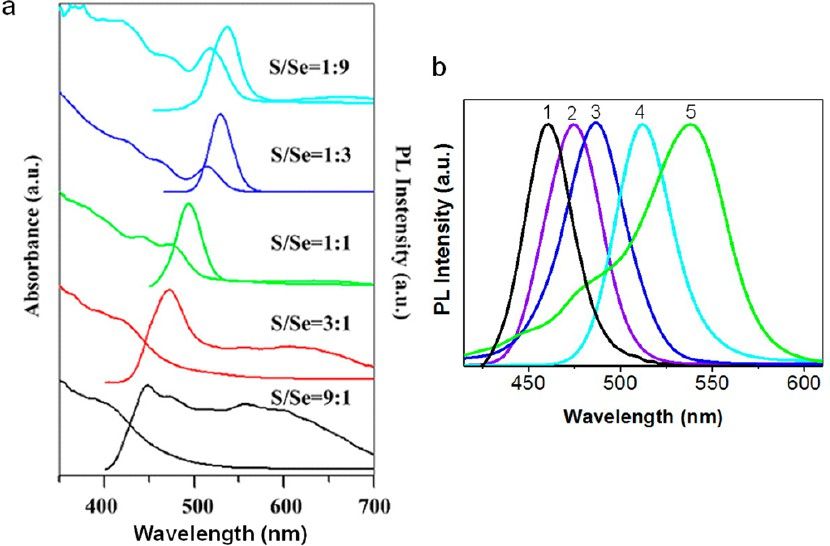
ACS Applied Materials & Interfaces Research Article
Figure 4. TEM and HRTEM (inset) images of the Zn0.5Cd0.5S0.25Se0.75 cores and core/shell QDs obtained under typical reaction conditions: (a)
TEM images of Zn0.5Cd0.5S0.25Se0.75 cores; (b) part a plus two monolayers of ZnS; (c) part b plus two monolayers of ZnS; (d) part c plus two
monolayers of ZnS; (e) part d plus two monolayers of ZnS. (a1−e1): Corresponding HRTEM of parts a−e.
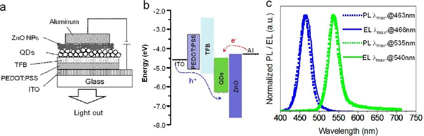
Figure 5. (a) Schematic of layers in the device structure. (b) Energy level diagram for the various layers. (c) Normalized photoluminescence spectra
(dashed lines) and EL (solid lines) spectra of blue−green QD-LEDs.
Figure 6. Electroluminescence performance of QD-LEDs with green emission: (a) current−density (J) and luminance (L) versus driving voltage
(V); (b) current efficiency versus luminance; (c) external quantum efficiency (EQE) versus current−density.
shell thickness, the lattice parameters decrease gradually toward co-N-[4-(3-methylpropyl)]-diphenylamine] (TFB) (30 nm)/
0.313 nm, which is consistent with that of zinc blende ZnS. The Zn1−xCdxS1−ySey/ZnS core/shell QDs (20 nm)/ZnO NPs (25
consecutive change of the lattice parameters can effectively nm)/Al to confine exciton formation within the QD layer. TFB
reduce the structural defects and improve the PL QYs. and ZnO layers were chosen as the hole-transporting and the
On the basis of this “green” and efficient synthesis method, electron-transporting layers, respectively, because of their high
we further explored the potential application of hole (electron) mobility with effective electron-(hole-)blocking
Zn1−xCdxS1−ySey/ZnS (x = 0.2, y = 0.1 for blue and x = 0.6, properties. Except for the Al cathode, which was deposited
y = 0.5 for green) core/shell QDs as emitters in blue−green through vacuum thermal evaporation, all the active layers were
LEDs. The structure of the QD-LEDs is schematically shown in spin-coated on top of ITO sequentially. Previous research
Figure 5a, the QD-LEDs were fabricated with layers of indium results have indicated the solvent orthogonality in such
tin oxide (ITO)/poly(ethylenedioxythiophene):polystyrene multilayer structure, which can successfully avoid compromis-
sulfonate (PEDOT:PSS) (40 nm)/poly[9,9-dioctylfluorene- ing the integrity of the underlying layers while depositing the
4263 dx.doi.org/10.1021/am400433y | ACS Appl. Mater. Interfaces 2013, 5, 4260−4265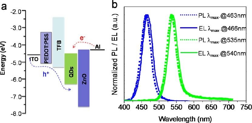
ACS Applied Materials & Interfaces                                                                                                          Research Article

Figure 7. Electroluminescence performance of QD-LED with blue emission: (a) current−density (J) and luminance (L) versus driving voltage (V);
(b) current efficiency and external quantum efficiency versus luminance.

overlayers.11 The schematic energy level diagram (Figure 5b)
shows that the ZnO nanoparticle layer not only provides
                                                                            ■    CONCLUSIONS
                                                                            In summary, we have synthesized nearly monodisperse
efficient electron injection from the Al cathode into                         Zn1−xCdxS1−ySey cores and high quality blue−green fluorescent
Zn1−xCdxS1−ySey/ZnS QDs but also helps to confine holes                      Zn1−xCdxS1−ySey/ZnS core/shell QDs with a “green” and
within the QD layer due to the valence band offset at the QD/                simple method. The PL QYs of these core/shell QDs reached
ZnO nanoparticle interface, leading to an improved charge                   75% and their FWHMs were kept below 40 nm. The QD-LEDs
recombination efficiency.11 Figure 5c shows the PL spectra of                 fabricated using Zn1−xCdxS1−ySey/ZnS core/shell QDs as
Zn1−xCdxS1−ySey/ZnS core/shell QDs and the electrolumines-                  emitters display high external quantum efficiency (0.8), and
cence (EL) spectra of the corresponding QD-LEDs. The blue−                  high maximum luminance values (4700 cd/m2) which is the
green LEDs have EL peaks at wavelength of 466 nm, and 540                   highest value in blue area ever and comparable to the brightness
nm and all QD-LEDs exhibit EL spectra with a narrow spectral                of the best QD-based LEDs. These results suggest that
bandwidth (fwhm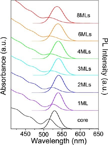
ACS Applied Materials & Interfaces                                                                                                        Research Article

  (3) Steckel, J. S.; Snee, P.; Coe, S.; Zimmer, J. P.; Halpert, J. E.;
Anikeeva, P.; Kim, L.; Bulović, V.; Bawendi, M. G. Angew. Chem., Int.
Ed. 2006, 45, 5796.
  (4) Kim, L.; Anikeeva, P. O.; Coe, S.; Steckel, J. S.; Bawendi, M. G.;
Bulović, V. Nano Lett. 2008, 8, 4513.
  (5) Sun, Q.; Wang, Y. A.; Li, L. S.; Wang, D.; Zhu, T.; Xu, J.; Yang,
C.; Li, Y. Nat. Photon. 2007, 1, 717.
  (6) Shirasaki, Y.; Supran, G. J.; Bawendi, M. G; Bulović, V. Nat.
Photon. 2013, 7, 13.
  (7) Cho, K.-S.; Lee, E. K.; Joo, W.-J.; Jang, E.; Kim, T.-H.; Lee, S. J.;
Kwon, S.-J.; Han, J. Y.; Kim, B.-K.; Choi, B. L.; Kim, J. M. Nat. Photon.
2009, 3, 341.
  (8) Kwak, J.; Bae, W. K.; Zorn, M.; Woo, H.; Yoon, H.; Lim, J.; Kang,
S. W.; Weber, S.; Butt, H.-J.; Zentel, R.; Lee, S.; Char, K.; Lee, C. Adv.
Mater. 2009, 21, 5022.
  (9) Peng, H.; Kang, C.; Liang, M.; Chen, C.; Demchenko, A.; Chen,
C.; Chou, P. ACS Appl. Mater. Interfaces 2011, 3, 1713.
  (10) Pal, B. N.; Ghosh, Y.; Brovelli, S.; Laocharoensuk, R.; Klimov, V.
I..; Hollingsworth, J. A.; Htoon, H. Nano Lett. 2012, 12, 331.
  (11) Qian, L.; Zheng, Y.; Xue, J.; Holloway, P. H. Nat. Photon. 2011,
5, 543.
  (12) Bae, W. K.; Kwak, J.; Lim, J.; Lee, D.; Nam, M. K.; Char, K.;
Lee, C.; Lee, S. Nanotechnology 2009, 20, 075202.
  (13) Bae, W. K.; Kwak, J.; Park, J. W.; Char, K.; Lee, C.; Lee, S. Adv.
Mater. 2009, 21, 1690.
  (14) Kim, T.-H.; Cho, K.-S.; Lee, E. K.; Lee, S. J.; Chae, J.; Kim, J.
W.; Kim, D. H.; Kwon, J.-Y.; Amaratunga, G.; Lee, S. Y.; Choi, B. L.;
Kuk, Y.; Kim, J. M.; Kim, K. Nat. Photon. 2011, 5, 176.
  (15) Kwak, J.; Bae, W. K.; Lee, D.; Park, I.; Lim, J.; Park, M.; Cho, H.;
Woo, H.; Yoon, D. Y.; Char, K.; Lee, S.; Lee, C. Nano Lett. 2012, 12,
2362.
  (16) Nevins, J.; Coughlin, K.; Watson, D. ACS Appl. Mater. Interfaces
2011, 3, 4242.
  (17) Wu, P.; Dai, Y.; Sun, T.; Ye, Y.; Meng, H.; Fang, X.; Yu, B.; Dai,
L. ACS Appl. Mater. Interfaces 2011, 3, 1859.
  (18) Peng, X.; Manna, L.; Yang, W.; Wickham, J.; Scher, E.;
Kadavanich, A.; Alivisatos, A. P. Nature 2000, 404, 59.
  (19) Wang, W.; Germanenko, I.; El-Shall, M. S. Chem. Mater. 2002,
14, 3028.
  (20) Zhong, X.; Feng, Y.; Knoll, W.; Han, M. J. Am. Chem. Soc. 2006,
128, 9002.
  (21) Zhong, X.; Feng, Y.; Zhang, Y.; Gu, Z.; Zou, L. Nanotechnology
2007, 18, 385606.
  (22) Zhong, X.; Han, M.; Dong, Z.; White, T. J.; Knoll, W. J. Am.
Chem. Soc. 2003, 125, 8589.
  (23) Shen, H.; Wang, H.; Zhou, C.; Niu, J.; Yuan, H.; Ma, L.; Li, L. S.
Dalton Trans. 2011, 40, 9180.
  (24) Shen, H.; Zhou, C.; Xu, S.; Yu, C.; Wang, H.; Chen, X.; Li, L. S.
J. Mater. Chem. 2011, 21, 6046.
  (25) Deng, Z.; Yan, H.; Liu, Y. J. Am. Chem. Soc. 2009, 131, 17744.
  (26) Xu, S.; Shen, H.; Zhou, C.; Yuan, H.; Liu, C.; Wang, H.; Ma, L.;
Li, L. S. J. Phys. Chem. C. 2011, 115, 20876.
  (27) Shen, H.; Wang, H.; Tang, Z.; Niu, J.; Lou, S.; Du, Z.; Li, L. S.
CrystEngComm 2009, 11, 1733.
  (28) Deng, Z.; Cao, L.; Tang, F.; Zou, B. J. Phys. Chem. B 2005, 109,
16671.
  (29) Deng, Z.; Mansuripur, M.; Muscat, A. J. Nano Lett. 2009, 9,
2015.
  (30) Schoos, D.; Mews, A.; Eychmüller, A.; Weller, H. Phys. Rev. B
1994, 49, 17072.
  (31) Xie, R.; Kolb, U.; Li, J.; Basché, T.; Mews, A. J. Am. Chem. Soc.
2005, 127, 7480.
  (32) Zhong, X.; Feng, Y.; Knoll, W.; Han, M. J. Am. Chem. Soc. 2003,
125, 13559.

                                                                              4265   dx.doi.org/10.1021/am400433y | ACS Appl. Mater. Interfaces 2013, 5, 4260−4265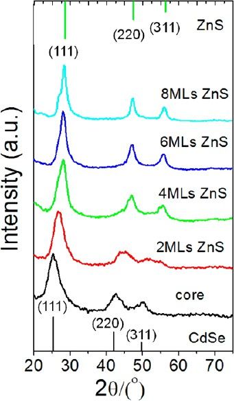
You can also read