CPF Series The Professionals Choice - Counter-top, Automatic Fill, Water Boiler (Professional Series) - With Filtration
←
→
Page content transcription
If your browser does not render page correctly, please read the page content below
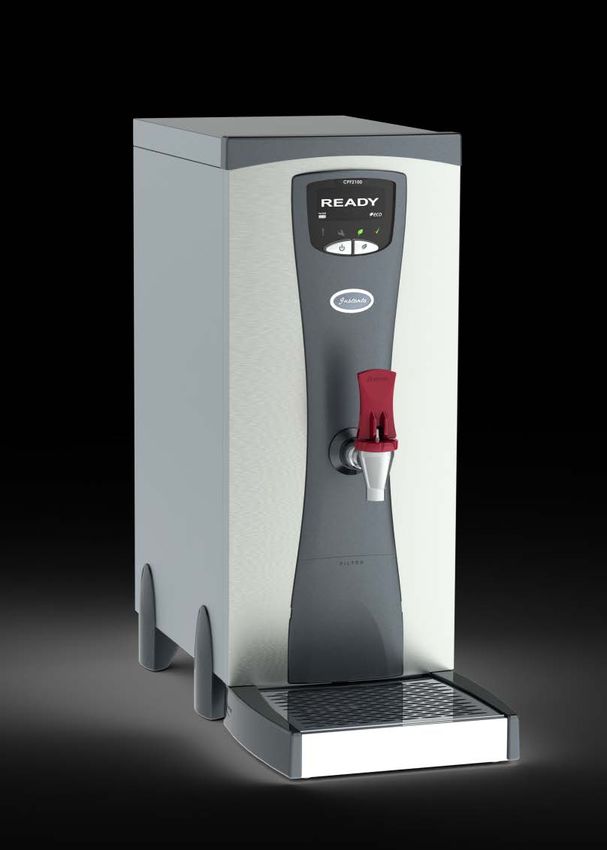
The Professionals Choice

CPF Series
Counter-top, Automatic Fill, Water Boiler (Professional Series) -
With Filtration

       Instanta Limited, Technical Support – Tel: 01704 502911 or 501114
INSTANTA LIMITED
SERVICE MANUAL
ISSUE: 1- Dated: March 2013
“CPF” SERIES
AUTOMATIC FILL, COUNTER-TOP WATER BOILERS
CONTENTS
Section: Page No:
Contents p.1
Introduction p.2
Principle of Operation p.2
1.0 Technical Specifications p.3 - 4
2.0 The Tank p.4
3.0 The LCD Display p.4 - 5
4.0 The Sensing Probes p.5
5.0 Thermistor p.6
6.0 Temperature Adjustment p.6
7.0 Heating Elements p.7
8.0 Triacs p.7
9.0 Printed Circuit Boards p.8
10.0 Thermal Cut-outs (over-boil & boil-dry) p.8 - 9
11.0 Solenoid Valve p.9
12.0 Filter & Filter Monitor p.9 - 10
13.0 Water Draw-off Tap p.10 - 11
14.0 Descaling p.11
15.0 Fault-Finding p.12
16.0 Service Warning Messages p.13 - 14
17.0 Exploded Drawing & Wiring Diagrams p.15 - 19
1INTRODUCTION:
The “CPF” series of counter-top water boilers were launched in November 2012 to
supersede the CT series which was manufactured between 2006 and 2012. The new
“CPF” series have taken the proven reliability and robust construction of their
predecessors and added a built-in filter and applied the latest advancements in
electrical design and technology to produce a catering boiler which is the most
advanced of its kind and yet easy to use and built to last.
The “CPF” series are inspected and tested in accordance with the company’s
ISO9001 Quality Management System and ISO14001 Environmental Management
System and conform with the protection requirements of the following standards and
specifications:
EMC Emissions and Immunity
EN55014-1:2006 +A1:2009 + A2:2011*
EN55014-2:1997 + A1:2001 +A2:2008*
EN61000-3-2:2006 + A1:2009
EN61000-3-3:2008
ROHS Manufactured in compliance with the requirements of the RoHS
Directive
WRAS Manufactured in compliance with the requirements of the UK Water
Regulations/Bylaws
All models in this range are similar in construction, but vary in size.
PRINCIPLE OF OPERATION:
When switched on, the machine first checks for water at the low-level (bottom)
probe. If no water is sensed at the probe, the solenoid is energised. If no water is
detected after approximately 5 minutes the solenoid switches off and the LCD
display reads “check water supply”. When water is detected at the bottom probe, the
heating element(s) is switched on to heat the water to the correct temperature. When
the set temperature is reached, the solenoid is pulsed on and off to allow water into
the boiler. The amount allowed into the boiler is controlled to maintain the
temperature. The heating element stays on during the filling cycle until the normal-
operating probe and specified temperature is reached.
When the boiler has reached the normal-operating probe and the correct
temperature, it goes into ‘idle’ mode. The heating element is pulsed periodically to
maintain temperature.
21.0 TECHNICAL SPECIFICATION:
CPF2100
Voltage: 220-240V single-phase 50Hz
Supply: AC
Rated Input: 3.0kW
Fill Type: Automatic Fill
Recovery per Minute: 0.5 Litres (3KW)
Rapid Draw-off: 10 litres
Heat-up time: 31 minutes (from empty to full capacity)
Height: 610 mm
Width: 260 mm
Depth: 555 mm (including drip-tray)
Avg. Power Consumption: 0.084 (kw/hour - standby)
CPF210
Voltage: 220-240V single-phase 50Hz
Supply: AC
Rated Input: 3.0kW
Fill Type: Automatic Fill
Recovery per Minute: 0.5 Litres (3KW)
Rapid Draw-off: 10 litres
Heat-up time: 31 minutes (from empty to full capacity)
Height: 705 mm
Width: 260 mm
Depth: 555 (including drip-tray)
Avg. Power Consumption: 0.084 (kw/hour - standby)
CPF310
Voltage: 220-240V single-phase 50Hz
Supply: AC
Rated Input: 6.0kW
Fill Type: Automatic Fill
Recovery per Minute: 1.0 Litre
Rapid Draw-off: 11 Litres
Heat-up time: 22 minutes (from empty to full capacity)
Height: 705 mm
Width: 260 mm
Depth: 555 mm (including drip-tray)
Avg. Power Consumption: 0.084 (kw/hour - standby)
CPF4100-3
Voltage: 220-240V single-phase 50Hz
Supply: AC
Rated Input: 3.0kW
Fill Type: Automatic Fill
Recovery per Minute: 0.5 Litres
Rapid Draw-off: 17 Litres
Heat-up time: 60 minutes (from empty to full capacity)
Height: 610 mm
Width: 360 mm
Depth: 555 mm (including drip-tray)
Avg. Power Consumption: 0.1 (kw/hour - standby)
3CPF4100-6
Voltage: 220-240V single-phase 50Hz
Supply: AC
Rated Input: 6.0kW
Fill Type: Automatic Fill
Recovery per Minute: 1.0 Litre
Rapid Draw-off: 20 Litres
Heat-up time: 35 minutes (from empty to full capacity)
Height: 610 mm
Width: 360 mm
Depth: 555 mm (including drip-tray)
Avg. Power Consumption: 0.1 (kw/hour - standby)
CT6000-6
Voltage: 220-240V single-phase 50Hz
Supply: AC
Rated Input: 6.0kW
Fill Type: Automatic Fill
Recovery per Minute: 1.0 Litre
Rapid Draw-off: 29 Litres
Heat-up time: 45 minutes (from empty to full capacity)
Height: 610 mm
Width: 440 mm
Depth: 555 mm (including drip-tray)
Avg. Power Consumption: 0.13 (kw/hour - standby)
2.0 THE TANK:
The tank lid is secured using M4 stainless steel screws. The lid is sealed with a
silicone rubber gasket. Silicone sealant secures the gasket to the tank, and the lid is
sealed with silicone grease. The tank body and lid are made from type-304 stainless
steel while the internal baffle plates are made from type-316 stainless steel (type-316
is more resistant to the corrosive properties and minerals found in some mains water
supplies in specific parts of the UK).
3.0 THE LCD DISPLAY (Digital Program Menu):
The LCD display informs the user of the boiler’s status (e.g. filling, heating, ready
etc.). The display also informs the user of potential fault conditions (e.g. no water
supply, clean probes, etc.).
The LCD display in conjunction with the On/Off and Eco button also gives access to
the program menu which allows various settings to be selected.
There are 2 levels that can be accessed in programming mode (USER PROG &
ENG PROG). These can be accessed as follows:
USER PROG - This gives the customer/user limited access to certain functions and
settings (e.g. time & day setting, temperature setting).
To access USER programming menu:
Switch boiler off and then back on again whilst press & holding the On/Off button in
(for approximately 10 seconds).
4ENG PROG - This gives the engineer access to all programming functions.
To access the engineer programming menu:
Turn the unit off and when turning back on, press & hold both and On/Off and
Eco button together for approximately 10 seconds until the screen goes red.
Continue to push the On/Off button to proceed through the 15 menu
selections until the desired mode is reached.
To select the mode, hold button in for 3 seconds.
Program Menu is as follows:
1. HOUR (adjustable: 0 – 24 hours)
2. MIN (adjustable: 0 – 59 minutes)
3. DAY (adjustable: 1 – 7 [1 been Sunday etc])
4. TMDE (Sets Timer: ON – OFF or ALL)
5. TMRS (Sets on/off periods – [ALL or Each day)
6. FSIZ (Sets litres throughput between filter changes:
Adjustable from 2000 – 19500 litres)
7. TEMP (Sets Temperature – 800C – 980C [default 960C])
8. FILT (Sets filter – On or Off)
9. PWUP (Power up mode – On, Off or Last Used)
10. ECO (ECO Button – On or Off)
11. ELEM (Sets Element power – 3, 6kw etc.)
12. SHWC (Show clock on display – On or Off)
13. VOLT (Displays incoming voltage)
14. TADC (Displays thermistor valves)
PLEASE NOTE: All new XEF500 circuit boards are supplied with default settings
suitable for 3KW models (CPF210, CPF2100 & CPF4100-3).
If a new PCB is fitted to a CPF4100-6 or a CPF6100-6, then the “ELEM” mode will
need to be accessed and the setting adjusted to the appropriate KW rating (6KW for
CPF4100-6 & CPF6100-6).
4.0 THE SENSING PROBES:
Sensing probes are used to detect the presence of water within the tank (5-13
second response time), using a small electrical current to make a circuit via the
water.
They are made-up from a PTFE insulator with a 316 stainless steel rod through the
centre.
There are five level sensing probes inside the tank (from bottom to top):
1. Low-level Sensor - Yellow wire
2. Eco Sensor - Grey wire
3. Normal Operating Sensor - Brown wire
4. De-scale warning Sensor - Orange wire
5. Overfill detection Sensor - Red wire
5NOTE: Only the low-level and Normal Operating sensors are used in normal
operation.
Common problem: Hard-water in some parts of the UK causes a build-up of lime-
scale on the sensing probes, which acts as an insulator (e.g. the sensor is no-longer
able to detect the presence of water). When a sensor becomes insulated, the water
level will switch to a different sensor and the CLEAN PROBES message will display.
5.0 THE THERMISTOR (thermal resistor):
The thermistor is an electronic device used in place of a thermostat, to measure the
temperature of water. It is constructed using a thermally sensitive resistor which
exhibits changes in electrical resistance with even a slight change in water
temperature, making it extremely accurate (+/- 1.2 degrees Celsius).
On the “CPF” series, the thermistor is stuck to the outside of the tank-front using
metal-set putty.
The LCD display will show thermistor valves (TADC Valves) in program mode.
Typical readings will be between 80 & 200 depending on temperature.
POSITION: - IMPORTANT: POSITION OF NEW THERMISTOR MUST BE THE
SAME AS THE OLD ONE.
Removal/replacement of thermistor: - To remove the old thermistor, chip it off
using the tip of a screwdriver.
To ensure that the new thermistor is correctly fitted to the tank, the metal-set
compound must be thoroughly mixed. To do this, fold the compound between your
fingers for at least one minute. Place the thermistor into the mixed compound and
apply the compound onto the cold tank,* ensuring that the head of the thermistor is
completely covered. The metal-set should completely harden in approximately 5
minutes.
* It is strongly advised that the tank should be cool before application of Metal-
Set
6.0 TEMPERATURE ADJUSTMENT:
The water temperature on the “CPF” series boilers can be digitally adjusted between
a range of 80 and 980 Celsius in 10C increments.
To adjust temperature, access the programme menu via the LCD display (see
Section-2). The factory-default temperature setting is 960 Celsius.
NOTE: For most end-users serving hot drinks, the optimum temperature setting will
be 94-960 Celsius.
67.0 HEATING ELEMENT(S):
The heating elements are made from Incoloy-800 material, which gives them a long
life expectancy. They are sealed into the tank by two blue silicone rubber washers
and secured by two 1/4”BSP brass lock-nuts.
ELEMENT RATING: 3KW, 230V
RESISTENCE: Between 19 and 20 Ohms
AMPS: Elements draw between 10 and 11 amps.
If the element has blown it will have an open circuit. To test this use a simple PAT
test.
Boil-dry Protection:
Each element has a brazed “hot-return” fitting, which accepts a stud-mount, 120^C
thermal cut-out switch. The live input to the element is directed through the thermal
cut-out switch. If the element overheats (boil-dry situation etc,), the thermal switch
picks up the rise in temperature and breaks the live supply to the heater. If this
happens, the thermal switch will need to be reset by pushing in the small button on
the top of the switch-body.
8.0 THE TRIAC:
The triac is a device used to switch the heating element on via a control signal from
the P.C.B. The triac generates heat, which has to be dissipated. This is done by
bolting it to the aluminium wiring tray using heat-sink compound between the surface
of the triac and the aluminium tray.
There are 2 types of triac used on the “CPF” series:
XE851 - all 3kw models and
XE854 - all 6kw models
If the triac fails, in 90% of cases it will fail ‘closed circuit’. This causes the heating
element(s) to remain on. If this happens, the machine will overheat. When steam
enters the air-vent pipe, the over-boil safety cut-out will detect a rise in temperature
and switch off power to the elements.
If the triac has failed ‘closed circuit’ there will be continuity between the live element
terminal (PCB) and live into the triac (GREY wire).
To test if the triac has failed (closed circuit), re-set thermal cut-out (if necessary),
leave machine plugged in and turn off at the ON/OFF switch (front panel). If the
machine continues to heat when switched off, the triac is faulty. If not, refer to
faultfinding “over-boiling”.
79.0 PRINTED CIRCUIT BOARDS:
MAIN P.C.B. (XEF500) – ALL “CPF” MODELS:
Operating Voltage: 190V – 265V AC @ 50Hz
Frequency Range: 50-60 Hz
Fuse Rating: 1A 250V AC
Operating temp: 0–70^C
Located on the aluminium wiring tray, beneath the tank. This P.C.B. controls the
main functions of the machine, monitoring the water level, water temperature, water
supply etc.
There are four board-mounted LED’s on the XEF500 main PCB as follows:
Continuous Flashing Amber = Processor is working OK
Green = Mains Supply to PCB
Red = Heating element is on
Amber = Boiler filling with water
Blue = Boiler Status Indication
The P.C.B. can be configured for use on either: 3kW or 6kW boilers. When supplied
from new, the software default is for 3kW models. To adjust and configure for use on
a 6kW boiler, the “ELEM” mode will need to be accessed and the setting adjusted to
the appropriate kW rating (6kW for CPF4100-6 & CPF6100-6) as described in
SECTION-2 “LCD Display”.
This configuration of the P.C.B. to match the kW rating of the boiler determines how
much water the software tells the inlet valve to put into the machine in one pulse.
Fault Diagnostics:
If a fault is detected, the user is warned via the LCD display (See chart on Page:
12/13 for details of the warnings and the possible causes).
LCD Display P.C.B. (XEF501) – All “CPF” models:
The XEF501 is purely a display system. The boiler will continue to function if it is
faulty, removed or damaged. The integrity of the system is reliant on the Main
XEF500 P.C.B. in terms of failure and safety.
See Section-2 “LCD Display” for details on how to access the program mode and
make adjustment to settings.
10.0 - THERMAL CUT-OUTS:
Over-Boil Protection – (Air-vent)
All machines have a thermal cut-out switch situated on the air vent. Its function is to
protect in the event of an over-boil situation arising - the thermal switch will cut power
to the heaters. After about 10 minutes, the LCD display will show the message “NOT
READY ELEM FAIL” on a red screen. (Note: Before 10 minutes, the display does not
indicate any fault – a normal message e.g. “Boiler Ready” is displayed). If the over-
boil cut-out has activated, switch the boiler off at the wall and back on again in 10
minutes once the boiler has cooled (thermal switch will reset and work as normal).
8The Dual-pole thermal cut-out differs from the single pole as both Live and Neutral pass
through it. To reset these you will need to access the cut-out when it has cooled and
press the red reset button in the centre.
Boil-Dry protection - (Element[s])
All heating elements have individual thermal cut-out switches fitted to them. If the
element overheats (boil-dry situation etc,), the thermal switch picks up the rise in
temperature and breaks the live supply to the heater. After about 15mins, the LCD
display will show the message “THERM DISC”. If this happens, the thermal switch
will need to be reset by pushing in the small button on the top of the switch-body.
11.0 THE SOLENOID VALVE:
The cold water inlet valve can operate between 2 bar and 7 bar (28-96psi) mains
pressure. The only serviceable part on the valve is the coil. The coil is susceptible to
water damage from steam or water leaks.
Disconnect boiler from electrical supply before replacing the solenoid valve.
Mains Water Pressure:
MAINS WATER PRESSURE RANGE: Between 2.0 and 7.0 bar (28 and 96psi)
Incoming mains water pressure can vary wildly from site to site and can also
fluctuate dependent on the time of day (water pressure often increases at night). In
extreme cases, this can take the mains water pressure outside that at which the
boiler can operate. In-coming mains water pressure of more than 100psi (7.0bar) can
bypass the solenoid valve and cause an overflow situation. In such circumstances, a
pressure reduction valve should be fitted to the pipework (before the machine), to
bring it to a level that the machine can cope with.
Similarly very low mains water pressure (below 28psi) can also result in the solenoid
valve being bypassed - insufficient water pressure prevents the valve from seating
correctly, although this is much less common.
12.0 – MULTI-FILTER & FILTER MONITOR:
The CPF Series incorporates a new built-in filtration system to ensure water is
always to the highest standard. The filtration works in three ways;
- Removes sediment (3 micron)
- Removes chlorine and taste & odour
- Reduces lime-scale
A series of bars on the LCD Display shows the estimated remaining life in the current
cartridge. When the filter has just 200 litres remaining (or a period of 6 months has
expired), the filter icon will begin to flash as a reminder. When the filter needs
replacing, the screen will show the message; CHANGE FILTER.
The boiler will continue to operate with the CHANGE FILTER screen but scale may
build up more rapidly.
9Filter Capacity:
The filter monitor is set to factory default (9001 litres) but can be adjusted to suit
(between 2500 and 19500 litres); see section 3 (access to program mode), to adjust.
Filter Age:
The age of the filter (in months), can be checked at any time. With boiler turned off,
press & hold both the On/Off and Eco buttons together until the screen shows
“FAGE” and the number of months elapsed (e.g. 3 = 3 months old).
Filter-life Monitor:
The filter-life monitor can also provide an accurate reading of how many litres remain
before the filter-cartridge expires. With boiler turned off, press & hold On/Off button
until screen shows “0000 Litres”.
13.0 - WATER DRAW-OFF TAP:
The draw-off tap is subject to wear & tear. The tap washer & spring will occasionally
require replacement. The tap-bonnet can also become worn overtime and may need
replacing. We strongly recommend that the draw-off tap is given a periodic
inspection as part of general maintenance routine to check for signs of ware & tear
(e.g. cracks appearing around the edge of the tap-bonnet, discolouration, and
grooves worn into the top surface of the bonnet). Replace parts as required.
Instanta Spares Centre can provide a screw-on upper tap-assembly (XTP1050/A) for
replacement or the separate components can be changed:-
To replace the tap washer: (Part No. TP1001/L)
Switch machine off.
Drain off water.
Unscrew bonnet and remove the upper tap assembly out of the tap body.
Remove the old washer from the tap spindle and firmly push the new washer onto
the spindle.
Screw the upper assembly back onto the body.
To replace the tap spring or tap bonnet. (Part No. TP1007/N & HSTP100)
Switch machine off.
Drain off water.
Push the pin out of the tap handle.(the pin has a bend in the middle)
Unscrew the metal bonnet to replace broken spring.(Small diameter down)
Replace bonnet and handle.
14.0 - DE-SCALING (Including cleaning probes):
Common problem: Hard-water in some parts of the UK will usually result in a build-
up of lime-scale within the tank. This can lead to a variety of different problems:
(i) One of the more common problems is caused by scale deposits coating one (or
more) of the five sensing probes - The scale acts as an insulator (e.g. the sensor is
no-longer able to detect the presence of water).
(ii) Heavy scale deposits on the inside of the tank can also affect the accuracy of the
temperature sensing device (thermistor), which is fixed to the outside of the tank with
10metal-set putty – The scale acts an insulator between the water and the stainless
steel tank-body, thus reducing the responsiveness of the thermistor, which can
eventually lead to an over-boil situation arising.
(iii) A heavy build-up of scale on the heating element(s) can also reduce their life
expectancy.
De-scaling Instructions:
Disconnect the machine from the power supply.
Remove the lid
Remove tank lid and internal baffle plates.
Remove as much loose scale as possible by hand.
Remove any hard scale coating the level sensing probes and insulators, using a
non-metallic scouring pad.
Use a good de-scaler to remove hard scale deposits. Leave for approximately 20
minutes.
Flush tank out with copious amounts of water, ensuring that all traces of de-scaler
are removed before re-assembly.
1115.0 - FAULT FINDING:
This section contains a list of faults and causes that the machine may encounter.
MACHINE CAUSE
SYMPTOM
Dead P.C.B. faulty - (1A fuse or transformer)
No mains input (installation or outside interference
fault)
On/Off switch faulty (board mounted on display)
Unsound terminal connection
Blown fuse in plug (3KW)
Bad connection in plug (mains lead fault)
Overfilling Water pressure too low or high (Section-11.0)
Contaminant sticking valve open
Water connected to overflow outlet (installation
error)
Not Filling Blocked inlet elbow
Blocked solenoid filter
Water turned-off
Kinked inlet hose
Water pressure too low or high
Solenoid coil failed (Section-11.0,)
Scaled-up Normal-Operating Probe (Sec-4.0)
Normal Operating Probe wire shorted out
Faulty element (See: Not Heating below)
Thermal Cut-out activated (Section-10.0)
No Draw Off Tap spring or washer fault (Section-13.0)
Over Boiling Temperature set too high (Section-6.0)
Faulty thermistor (Section-5.0)
Faulty triac (Section-8.0)
Machine not filling (Section-11.0)
Machine scaled up (Section-14.0)
Not Heating Thermal cut-out switch tripped (Section-10.0)
Faulty element (Section-7.0)
Faulty triac (Section-8.0)
Faulty P.C.B. (Section-9.0)
Unsound connection on element or triac
P.C.B. Blown Steam (See over-boiling above) or water damage
Element blown (1A fuse on P.C.B.)
Triac blown (Section-8.0)
Taste Problems Washing machines or dish washer on same feed
BLUE or RED hoses on same feed
Outside interference
Expired cartridge-filter
Foreign body in boiler
16.0 - SERVICE WARNING MESSAGES (see chart below):
12SCREEN MESSAGE BOILER STATUS POSSIBLE CAUSES ACTION TIMINGS
Filter cartridge is exhausted and should be Replace filter cartridge
READY
Fault shows
Screen
White
In READY and replaced as soon as convenient (available from Instanta
after approx. 6
NOT READY mode Spares)
CHANGE months
FILTER “Flashing” Part No: AQ35
Water turned off Check water supply and Fault shows
CHECK WATER after 20 pulses
Inlet hose kinked or bent stop-cock
Screen
White
of inlet valve
In READY and Low in-coming water supply Check in-coming water
READY NOT READY mode Fault inlet valve supply is at min of 2 bar
(approximately
2 mins)
Check solenoid valve
CLEAN PROBES Bottom probe not recognised. Clean & de-scale probes. Fault shows
after a 3-4
Yellow
Screen
NOT In READY mode Check probe wires are
months in hard
water area
READY secure.
CLEAN PROBES Top Probe not recognised. Water level has Clean & de-scale probes. Fault shows
reached the de-scale probe after a 3-4
NOT
Yellow
Screen
In READY mode months in hard
READY
water area
Flashing”!” & Triangles
Top probe & de-scale probe not recognised. Clean & de-scale probes.
NOT Water level has reached the overfill probe Fault shows
Screen
In NOT READY mode Check water pressure is after several
READY
Red
between 2 & 7 bar months in hard
water area
OVER-FILL
Flashing Red Spanner & Triangles
Thermistor disconnected or wires trapped/cut Check thermistor is
NOT plugged securely into PCB
and wires are not
READY
Screen
broken/trapped. Fault shows
Red
Immediately
In READY mode
ELEM FAIL UNLIKELY - UNLESS FAULT APPEARED
WHILST ENGINEER WORKING ON
Flashing Red Spanner & Triangles BOILER Thermistor fault - disconnected or wires cut
Screen NOT (on initial heat-up) Check thermistor is Fault shows
after 2 mins
plugged securely into PCB
READY
Red
In NOT READY mode and wires are not following
broken/trapped. switch-on from
cold.
THERM DISC
Red flashing Spanner & Triangles
Fault on heating circuit – either due to: 1). Over-heating - Reset Fault will show
over-boil safety switch. after approx. 10
1) Over-heating (scale-build-up affecting Check for limescale - de- mins after over-
scale as required boil
thermistor accuracy leading to over-boil
NOT switch activating), or Triac failed O/C Check Triac not failed O/C
READY
Screen
causing over-boil leading to over-boil
Red
Fault will show
In NOT READY mode switch activating. 2). Not Heating – check after 15 mins
ELEM FAIL power to heating circuit. following
2) Not heating (over-boil safety switch or Check both over-boil & boil switch-on from
Red flashing Spanner & Triangles boil-dry safety switch either activated or dry safety switches. Check cold (circuit
faulty, element fault, main PCB). element, check main PCB looks for a 2^C
Change component rise in temp
over 15 mins)
Fault on heating circuit whilst in normal 1). Over-heating:
operation (Ready mode): Reset over-boil safety Fault will show
switch. after
Check for limescale - de- approximately
1) Over-heating (scale-build-up affecting
NOT thermistor accuracy leading to over-boil scale as required 90 mins (circuit
has to see an
READY switch activating), or Triac failed O/C causing Check Triac not failed O/C
Screen
8^C drop in
over-boil leading to over-boil switch
Red
temp for fault
ELEM FAIL In READY mode activating. 2). Not Heating: to show)
Check heating circuit:
Red flashing Spanner & Triangles 2) Not heating (over-boil safety switch or boil- Check both over-boil & boil
dry safety switch either activated or faulty, dry safety switches.
element fault, main PCB). Check element,
Check main PCB
Change component
Fault on main PCB or an external electrical Check power supply to the Boiler will not
Dead BOILER installation fault boiler. Check PCB board – switch on and
“DEAD” mounted 1A fuse. screen will be
blank
Check main PCBInstanta
CPF310, CPF4100-6,
CPF SERIES CPF6100-632
27
38
30
31
9
8
25
33
6
29
37 28
7 10
4
14
13 11
2 3
36
1
41 12
26
16
40
23
5
18 15
20
35
17 24
19 39
22
34 21 D.80
CPF2100Exploded Drawing Key for CPF2100 (Drawing D.80)
Number Description Part Number
1 Complete Draw-off Tap XTP500
2 Tap Extension XTP1018/C
3 Yellow Tap Washer XWSH2
4 Grey Front Moulding XEF608 (CPF2100, 210, 310)
XEF609 (CPF4100, 6100)
5 Filter Door XEF604 (CPF2100, 4100, 6100)
XEF607 (CPF210, 310)
6 Display Window XEF615
7 Rubber On/Off Button XEF601
8 Display PCB XEF501
9 Display Back Box XEF606
10 Grey Water Feed Tube ACC309/S
11 Heating Element XEN200
12 Blue Rubber Element Washers XEN100/W
13 White Probe Holder E305A
14 Stainless Steel Probe PRB1/C
15 Thermal Cut-out (Over-boil) XETR7
15 Dual-Pole Thermal Cut-out (from Jan 2014 – check serial number) (CPF210 – FJ010160, XETR6
CPF310 – FK009110, CPF2100 – FA012474, CPF4100-3 – FB009090, CPF4100-6 – FD009070 & CPF6100-6 –
FE009060)
16 Thermal Cut-out (Boil-dry) XETR5
17 Solenoid Valve SOL21
18 Plastic JG Elbow (3/8 Stem to 3/8 Barb) JGXEF2
19 Plastic JG Elbow (3/8 Stem to 3/8 Push-fit) JGXEF1
20 3M Filter Head AQ35H
21 PCB XEF500
22 Triac XE851 (3kw) XE854 (6kw)
23 Rubber Breather Tube SR52
24 Terminal Block E1254
25 Overflow Gauze Assembly Ring spares
26 Cable Gland E318
27 Tank Lid Ring spares
28 Tank Ring spares
29 Overflow Tube (welded into tank) N/A
30 Upper Lid Baffle Ring spares
31 Lower Tank Baffle plate Ring spares
32 Machine Main Lid Ring spares
33 Rubber Tank Gasket XEN2G/N (CPF2100, 210, 310) XEN4G/N
(CPF4100)
XEN6G/N (CPF6100)
34 3M Filter AQ35
35 Brass Cut-out Mount XETR80 (3kw) XETR80/L (6kw)
36 Thermistor Fixing Position on Tank (Temperature Sensor) XE851
37 Probe Hex Nut T514/P
38 Water Inlet Elbow N/A
39 JG 3/8 Blue Plastic Tube JGS3/8
40 Tap/tank Adaptor XTP2019 (CPF2100, 210, 310, 4100)
XTP2019/L (CPF6100)
41 Grey tap-seal O-ring XWSH14WD127 - Issue 2
L
E GREEN/YELLOW – 11 to 15
SOLENOID
N
BLUE – 5
BROWN – 3
VIOLET – 7
BLACK – 6
BLUE – 2
N
HEATING PINK
ELEMENT
L
BLUE – 5A
RED
10
THERMAL
XETR5 CUT-OUT PINK BLUE VIOLET BROWN
(ELEMENT)
RED
FUSE
9
1 AMP
THERMAL
XETR7 CUT-OUT
(AIR VENT)
BROWN – 3
GREY – 4
PINK – 1
XE85 1
BLACK
YELLOW
BLUE
XEF500
LCD DISPLAY
RED
BLACK 6-CORE – 22 GREEN
WHITE THERMISTOR
RED – 16
ORANGE – 17
BROWN – 18
GREY – 19
YELLOW – 20
GREEN – 21
NOT USED
Instanta
CPF2100, CPF210,
CPF SERIES CPF4100-3WD128 SINGLE POLE
L
E GREEN/YELLOW – 15 to 19
SOLENOID
N
BLUE – 6
BROWN – 3
VIOLET – 8
BLUE – 5
BLACK – 7
BLUE – 2
N
HEATING
PINK
ELEMENT
L
RED
RED
13
14
THERMAL
CUT-OUT XETR5 PINK BLUE VIOLET BROWN
(ELEMENTS)
RED
RED
11
12
FUSE 1 AMP
THERMAL
CUT-OUT XETR7
(AIR VENTS)
GREY – 4
RED – 10
PINK – 1
RED – 9
XE854
BLACK
YELLOW
BLUE
XEF500
LCD DISPLAY
RED
BLACK 6-CORE – 26 GREEN
WHITE THERMISTOR
RED – 20
ORANGE – 21
BROWN – 22
GREY – 23
YELLOW – 24
GREEN – 25
EMPTY
PROBES
Instanta
             CPF310, CPF4100-6,
CPF SERIES CPF6100-6WD126
L
E GREEN/YELLOW – 11 to 15
BLACK – 6
SOLENOID
N
BLUE – 5
BROWN – 3
VIOLET – 7
BLUE – 2
N
HEATING PINK
ELEMENT
L
BLUE – 5A
RED
10
THERMAL
XETR5 CUT-OUT PINK BLUE VIOLET BROWN
(ELEMENT)
RED
FUSE
9
1 AMP
THERMAL
XETR6 CUT-OUT
(OVERFLOW)
GREY – 4
PINK – 1
RED – 3
XE851
BLACK
YELLOW
BLUE
XEF500
LCD DISPLAY
RED
BLACK 6-CORE – 22 GREEN
WHITE THERMISTOR
RED – 16
ORANGE – 17
BROWN – 18
GREY – 19
YELLOW – 20
GREEN – 21
NOT USED
Instanta CPF2100, CPF210,
CPF4100-3
CPF SERIES DUAL POLEWD129 DUAL POLE
L
E GREEN/YELLOW – 15 to 19
SOLENOID
N
BLUE – 6
BLUE – 5
BROWN – 3
VIOLET – 8
BLACK – 7
BLUE – 2
N
HEATING
PINK
ELEMENT
L
RED
RED
13
14
XETR5 PINK BLUE VIOLET BROWN
RED
RED
12
11
FUSE 1 AMP
XETR6
GREY – 4
RED – 10
PINK – 1
RED – 9
XE854
BLACK
YELLOW
BLUE
XEF500
LCD DISPLAY
RED
BLACK 6-CORE – 26 GREEN
WHITE THERMISTOR
RED – 20
ORANGE – 21
BROWN – 22
GREY – 23
YELLOW – 24
GREEN – 25
EMPTY
PROBES
Instanta
CPF310, CPF4100-6,
CPF SERIES CPF6100-6You can also read