Highly Improved Thermionic Energy Converter
←
→
Page content transcription
If your browser does not render page correctly, please read the page content below

Journal of Physics: Conference Series

PAPER • OPEN ACCESS

Highly Improved Thermionic Energy Converter
To cite this article: D. K. De et al 2019 J. Phys.: Conf. Ser. 1378 022001

View the article online for updates and enhancements.

                                This content was downloaded from IP address 46.4.80.155 on 21/01/2021 at 03:22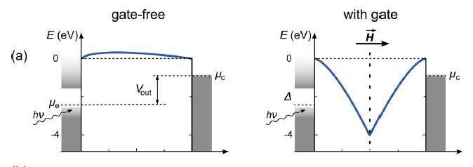
International Conference on Engineering for Sustainable World                                                      IOP Publishing
Journal of Physics: Conference Series             1378 (2019) 022001                         doi:10.1088/1742-6596/1378/2/022001

 Highly Improved Thermionic Energy Converter
                               D. K. Dea,b, O. C. Olawolea,e, S. O. Oyedepoc, E. S. Joela, O. F. Olawoled, M. E.
                               Emeterea, aOmeje M and U I Ikonoa and H M Nguyene,f

                               a
                                Department of Physics, Covenant University, Ota, Ogun State, Nigeria. bSustainable
                               Green Power Technology, Texas, USA. cDepartment of Mechanical Engineering,
                               Covenant University, Ota, Ogun State, Nigeria. dDepartment of Physics, Mountain Top
                               University, Ibafo, Ogun State, Nigeria.
                               e
                                 Division of Computational Physics, Institute for Computational Science, Ton Duc Thang University, Ho Chi Minh
                               City, Vietnam fFaculty of Electrical and Electronics Engineering, Ton Duc Thang University, Ho Chi Minh City,
                               Vietnam Corresponding author email: dilip.de@covenantuniversity.edu.ng

                               Abstract
                               Thermionic energy converter (TEC) has recently received significant attention, for it
                               holds potential for clean energy generation with a very high theoretical conversion
                               efficiency (60%). For the latter to be achieved, some of the key hurdles are to be
                               overcome. This paper discusses all these key hurdles along with modelling of solar
                               energy conversion using a TEC with nano-materials and metals, using the modified
                               Richardson-Dushman equation, which best describes the thermionic emission current
                               density from these materials. Using two scenarios: allowing natural heat radiation
                               from the back surface of the collector and using controlled heat collection from the
                               collector to maintain it at a fixed temperature. We then discuss results of simulation
                               of the conversion efficiency as a function of temperatures of emitter and collector,
                               work functions and Fermi energy of emitter and collector at absolute zero
                               temperature, solar insolation, the radius of parabolic concentrator and emissivity of
                               radiating surfaces. We discuss the impact of neglecting the radiation losses on the
                               efficiency evaluation as has been done by other workers recently. We suggest some
                               innovative ways to reduce significantly the space charge effect to make a solar TEC
                               a reality.
                               Keywords: Thermionic energy converter; solar energy; modelling; modified
                               Richardson-Dushman equation; metals; nanomaterials; high conversion efficiency;
                               clean energy, parabolic concentrator.

 1.       Introduction
  Significant research interest is currently focused on the thermionic conversion of heat energy to
  electrical energy/power using thermionic energy converter (TEC), because like solar PV, TEC
  offers a very clean energy generation technique with absolutely no pollution [1,2]. However,
  unlike solar PV, TEC has a special advantage of giving very high output power density (per unit
  area of TEC active surface) [2,3]. No power converter can match TEC in output power density,
  making it most ideal for space application [3,4]. It uses the principle of thermionic emission of
  electrons from a heated solid surface (below the melting point). The thermionic current density J
  at temperature T(K) is, in general, guided by Richardson-Dushman’s (RD) equation [5–7].

                                                                                                                               (1)

   Hence,      is the work function of the emitter,        is the Boltzmann constant. The emitted
   electrons, when collected by a colder anode (collector), constitutes electrical current that can drive
   a load in Figure 1 [8].

              Content from this work may be used under the terms of the Creative Commons Attribution 3.0 licence. Any further distribution
              of this work must maintain attribution to the author(s) and the title of the work, journal citation and DOI.
Published under licence by IOP Publishing Ltd                          1
International Conference on Engineering for Sustainable World IOP Publishing
Journal of Physics: Conference Series 1378 (2019) 022001 doi:10.1088/1742-6596/1378/2/022001
Figure 1: Schematic diagram of the thermionic energy converter [8]
In the next section, we consider (i) new development in TEC (ii) reduction of space charge effect
(iii) principle of thermionic energy converter TEC and the use of graphene as emitter and collector;
(iv) theory of the solar TEC and finally we present our own works on solar thermionic energy
conversion efficiency with graphene as emitter and collector
2 New development in TEC
Solar thermionic power generation is currently receiving attention [3,4,9–12]. The SLAC/Stanford
University research team is creating a new solid-state energy conversion technology based on
micro-fabricated heterostructure semiconductor cathodes with appropriate band engineering and
photon-enhanced thermionic energy converters (PETECs)[8,12]. The microfabrication allows a
very small gap (a few microns) between the emitter and collector and thus reduces the space charge
effect drastically. When used as a topping cycle in concentrated solar thermal electricity generation,
PETECs is expected to enable total system efficiencies in excess of 50%. However, a practical
device has not yet been realized using PETEC and micromachined is discussed also below.
Solar TEC is promising for future use as a topping cycle in concentrated solar thermal and in
concentrated photovoltaic stations. However, to our knowledge, a practical solar TEC has not been
realized yet. Recently, theoretical research has been focused on modelling solar TEC where solar
energy is concentrated onto the emitter surface by a parabolic concentrator [3,10,14]. The latest
work in this direction shows for the first time the importance and method of controlling the collector
temperature in a solar TEC. This is important to achieve the desired efficiency after the space charge
effect is reduced by the architectural combination of magnetic field and electrode gates.
Many emitter materials have work functions in the range of 3 to 4.5 eV. These require very high
temperature (above 2000 K) to generate notable current density. Except for a few refractory metals
(such as Tungsten), most materials have a melting point below 2000 K and therefore not suitable
for high-temperature TEC. Even though intensive researches are being conducted to lower the work
function of materials, they are still at a developmental stage for application to TEC. Tungsten and
graphene are special materials for TEC since both have high melting points. For higher efficiency
of TEC, it is important that the emitters should have a high melting point since efficiency increases
with the temperature of operation. In places where sunshine is abundant, like in many Asian and
African countries and parts of USA, high temperature at a small area of the emitter (1- 4 cm2) can
be created using parabolic concentrator.
Nanomaterials (emitters) with a high melting point are receiving attention for the conversion of
the thermal energy to electrical power by thermionic energy converters (TECs) [8,15]. The
addition of electrostatic gating method with a Cs/O surface coating on large area monolayer
graphene grown by chemical vapour deposition and then transferring onto 20 nm on Si that
enables high electric fields capacitive charge accumulation in the graphene, as to reduce the work
function of graphene from 4 [15]. Such ultra-low work function graphene is an
ideal candidate for graphene as the thermionic emitter in TEC, specifically, for low-temperature
2International Conference on Engineering for Sustainable World IOP Publishing
Journal of Physics: Conference Series 1378 (2019) 022001 doi:10.1088/1742-6596/1378/2/022001
TEC [16]. Liang et al. [17] proposed and theoretically studied a solid state thermionic device
comprising of van der Waals heterostructures of suitable multiple layers of transition metal
dichalcogenides such as , , and sandwiched between two graphene
electrodes to waste heat at 400 K and found efficiencies in the range of 7% to 8%. Being a high-
temperature material, graphene is a suitable material for thermionic energy conversion,
specifically, if the work function of graphene can be reduced from around to around
, using some of the technologies as mentioned above [18]. Technologies have been
maturing for growth of mono to multilayers of graphene (Gr) on silicon carbide [19,20]. The latter
is a material that also can sustain high temperature. Epitaxial Gr on silicon carbide (SiC) holds
great promise for the development of new device concepts based on the vertical current transport
at hetero-interface [21]. Work function modulation of graphene on SiC has also been
obtained recently through the controlled use of nitric acid [21]. Recently Kwon et al. (2012) [22]
reported a chemical approach to the lower work function of graphene using
, , , . The work functions are reported to be 3.7 eV, 3.8 eV,
3.5 eV and 3.4 eV. Such remarkable property along with good electrical conductivity, high
dielectric constant makes engineered graphene an ideal candidate to be used as both emitter and
collector in a thermionic energy converter.
Graphene has distinguished itself from semiconductor and the other nanomaterials due to superior
properties in the linear band structure, ultrahigh electrical conductivity, high stiffness light weight
and extreme mobility [23]. Graphene emitter, therefore, is as a good candidate for the thermionic
engine. It has its place because of the presence of free electron in the linear band structure, which is
in proximity to Fermi level, that is deficient in macro material [24–29]. Alteration in the chemical
potential across the graphene sheet provides room to tuning the intrinsic Fermi level (Chemical
potential, µ) to corresponding Dirac point by choice of the investigator [30], and thus the work
function , . Graphene has attractive features and a lot of applications in nano-
electronics [31,32] energy storage [33], and composites [34]. Thus, graphene can become the ideal
candidate for thermionic power generation with the use of solar concentrators as shown in Figure
3a. Thus, it is expected that with the advent of new science and technology, several layers of
graphene on silicon carbide can be deposited such that work function can be controlled at ease from
around to around , as desired, while retaining its high-temperature tolerance.
2.1 Reduction of space charge effect
Space charge is formed in between the emitter and collector space (which is to be maintained at
vacuum and may be filled with positive caesium ions) when all the emitted electrons from emitter
could not be collected by the anode simultaneously.
In recent time, a revolutionary modification of TEC was proposed and demonstrated. Simply by
filling in the inter-electrode gap of the TEC with a nanofluid, which consist of gold nanoparticles
dispersed in tetradecane base fluid, Nguyen et. al. [13] removed most of the aforementioned
limitations and introduced many advantages toward further potential applications of TECs. In
addition to direct thermionic emission from the cathode to the anode, this modification added an
indirect charge transport channel via the nanoparticles Firstly, by changing from the gas phase to
fluid phase, the space charge effect is reduced naturally. Secondly, by interactions with the
nanoparticles that form temporary potential barriers for nano-hopping or tunnelling of electrons,
the escape energy (work function) of any cathode material can be effectively lowered. Moreover,
the requirement of the high-temperature contrast between cathode and anode can be tolerant; and
the output current density of a nanofluid TEC was demonstrated to be strongly enhanced. However,
3International Conference on Engineering for Sustainable World IOP Publishing
Journal of Physics: Conference Series 1378 (2019) 022001 doi:10.1088/1742-6596/1378/2/022001
because the theoretical platform for this new concept is still under developing, further discussion
on its theory is outside the scope of this paper. The nanofluid device is of course benefit from new
developments that will be discussed next in this review paper.
These space charges can be minimized by (i) keeping the separation between emitter and collector
of the order of micron; (which is very difficult while maintaining a significant temperature
difference between the two electrodes), (ii) applications of the magnetic field, and gate voltage
(Figure 2c). The latter is an innovative technique shown to be effective6. Guided by accelerating
electric field and cycloidal path motion in the magnetic field, the electron scattering is reduced
significantly. The diameter of the holes in the gate must be such that (i) it allows fairly uniform
electric field directed normal to the emitter; (ii) while maximizing the hole space in the gate as
much as possible (to minimize gate current), (iii) it should be slightly larger than the cyclotron
radius of most electrons. A high magnetic field can accomplish the latter [3,10,14].
In particular, this scientific work jettisons the effect of space charge in the TEC. Partial space
charge neutrality could be accomplished as shown in Figures (2b and 2c) together with the
following criteria: Nanoengineering could be adopted to configure the emitter in a pencil-like
manner with height and diameter . For a total collection of emitted electrons
approximately 99.8 % on collector plate, there is a need to insert a gate electrode with diameter
holes at an approximate distance in between the emitter and collector.
Consequentially, the diameter hole of the gate should double the radius of the cyclotron of
the liberated electron. Hence the mean free path of the liberated electron is expressed as
mv m = Berc (2a)
a b c
Figure 2: (a) shows that the work function W of the emitter is greater than that of the collector in the absence of gate at the inter-
electrode. The difference is equal to about. (b) insertion of a positive gate between the cathode and collector, with a hole
of radius R and a magnetic field at a right angle to the gate towards the collector [4] (c) reduction of space charge effect in
TEC via the inclusion of gate and magnetic field [4,35]
(2b)
where is the mean velocity of the emitted electrons, m is the electron mass and is the
Boltzmann’s constant and typifies the radius.
3 Principles of Thermionic Energy Converter (TEC)
The principle of thermionic energy conversion has been explained lucidly in [8]. The
output power in a TEC (Fig.3),
4International Conference on Engineering for Sustainable World IOP Publishing
Journal of Physics: Conference Series 1378 (2019) 022001 doi:10.1088/1742-6596/1378/2/022001
(3a)
(3b)
where is the emitter current and is the collector current. s is the area of emitter which is equal
to that of the collector in this modelling. Again, the separation between emitter and collector has to
be very small to reduce the space charge effect (discussed earlier), specially, in absence of gate and
magnetic field control (discussed earlier) so that, the electric field is strong to pull the
emitted electrons fast onto the collector, in order to minimize the space charge problem. The space
charge will affect the net output power.
The emitter and collector current density and depend not only on emitter and collector temperatures
, , their work functions , , the distance between the two plates but also
arrangements that control space charge. The accuracy of the modified Richardson-Dushman Equation
in predicting the current density of graphene and carbon nanotube over Richardson Equation and
Liang and Ang27 model has been reported [36,37].
In addition, Figure 3a shows how the centre of the cathode-anode configuration is positioned on the
axis of the parabolic concentrator and at a right angle to it. In order, to allow all the solar irradiation
to be concentrated on the emitter in Figure 3a, the cathode-anode configuration must be strategically
placed at a height h. Also, a nanoscale coating could be done for more absorption and low reflection
of solar irradiation on the surface 1 of Figure 3b.
Moreover, we assume that large size (2- 6 m diameter) parabolic concentrators may be possible one
day and that the graphene emitter (on silicon carbide) of the TEC is placed on the axis of the parabolic
concentrator [Figure 3a]. We assume that a magnet can be attached with its south pole on the collector
and the magnet can be cooled at a rate . We then consider the energy exchange processes that take
place in such a graphene TEC and compute the efficiency of the graphene TEC for various parameters
such as, solar insolation, anode temperature, diameter of parabolic mirror, emitter height (which
determines the effective emitter cross-section) from the base of the mirror, mirror reflection
coefficients etc. To our knowledge, such a theoretical concept of computation of efficiency of
graphene TEC has not been applied by other workers and it is different from those discussed earlier
in a different model [3,10,14]. The calculation of efficiency in a TEC by other workers so far has
excluded radiation heat losses and energy conservation processes [38]. In this paper, we have
considered graphene surfaces on SiC and assumed that the graphene surfaces can be suitably
engineered for work functions to be used as emitter and collector in a solar TEC. We shall not dwell
on the space charge effect that limits the power put from a TEC. This thermionic energy converter
reduces the dependence on silicon and has the potential to charge a battery that can be used during
off-peak of sunshine.
5International Conference on Engineering for Sustainable World IOP Publishing
Journal of Physics: Conference Series 1378 (2019) 022001 doi:10.1088/1742-6596/1378/2/022001
a
b
Figure 3: (a) Dependence of upon [8,14,39] (b) Nanoscale coating of TEC plate [8,14]
The relationship that exists among radius , height h and emitter area , parabolic height , parabolic
radius , the angle the parabolic mirror makes with its base and the focal length of parabolic
concentrator can be expressed mathematically as[14]:
(4)
(5)
(6)
4 Theory of the solar TEC
An electron emitted from the emitter at temperature will require net average energy of
. Solar energy is concentrated by the parabolic mirror on to the emitter of area
s (surface 1 in Figure 3b). S is the area of the circular cross-section of the mirror (Figure 3a). The
electron emission takes place from the second surface of the emitter. This can be achieved by
covering the first surface with a thin quartz encapsulation and making the work function of the second
surface somewhat lower than the first surface. Even if that is done, the first step should suffice to
prevent continuous electron emission from the first surface. Then energy conservation demands that
the following equation holds:
(7)
In Equation (7) , and are respectively the temperatures of the first, second surfaces of the
6International Conference on Engineering for Sustainable World IOP Publishing
Journal of Physics: Conference Series 1378 (2019) 022001 doi:10.1088/1742-6596/1378/2/022001
emitter and the first surface of the collector. The first surface of collector's faces and collects the
electrons emitted from the second surface of the emitter.
Here is the collector current density. As discussed above collector work function. The
efficiency of solar power conversion is then given by:
(8)
From Equation (8) alone it is not possible to know and with known values of , , and
. Considering the dynamics of energy exchange processes that take place in a solar TEC (Figure
3) the following equations hold for the
emitter of thickness [8,14]:
(9)
(10)
(11)
(12)
where for bulk material or thick surface and for a 2-D thin surface. Now we see from Eqs. (1)-
(12), which provides an ideal model for a solar TEC, that it is a non-trivial job to solve analytically
for , , and hence Equation (8) for the efficiency of the solar TEC.
In this paper, we want to study particularly the effect of work function and temperature of the
collector in the efficiency of a solar TEC, keeping We (work function of the emitter) fixed at high
value of 4.5 eV. This value is close to the work function of tungsten and graphene without any
surface work to reduce the work function. In so doing, we want to simplify the model by assuming
both emitter and collector to be thin enough so that these can be characterized by temperatures,
(13)
(14)
Then Equations (8 and 9) can be written as:
(15)
(16)
7International Conference on Engineering for Sustainable World IOP Publishing
Journal of Physics: Conference Series 1378 (2019) 022001 doi:10.1088/1742-6596/1378/2/022001
In this simulation, we assume two parabolic concentrators with a circular aperture of radius
and ; As high temperature is needed to obtain good efficiency, the cross-
section of the emitter has to be small. We choose two emitter cross sections in these simulations:
; . Assuming , Tables 1 and 2 show simulated
efficiency of TEC in the absence space charge problem and reflection coefficient of the
parabolic mirror and absorption coefficient of the emitter surface for the reflected and
concentrated solar light energy.
Table 1: Simulated efficiency for various solar insolation with parabolic concentrator of radius with for
emitter cross section MRD Model
R(m) I0= 500 I0= 600 I0= 700 I0= 800 I0= 900 I0= 1000
W/m2 W/m2 W/m2 W/m2 W/m2 W/m2
1 22.2 22.6(1764) 23 23.4 23.6 23.8(1838)
2 25.1 25.4(1974) 25.7 25.9 26.1 26.3(2064)
Table 2: Simulated efficiency for various solar insolation with parabolic concentrator of radius with for
emitter cross section MRD model
R(m) I0= 500 I0= 600 I0= 700 I0= 800 I0= 900 I0= 1000
W/m2 W/m2 W/m2 W/m2 W/m2 W/m2
1 21 21.5(1768) 21.8 22.2 22.4 22.7(1840)
2 23.9 24.2(1974) 24.5 24.7 24.9 25(2064)
Table 3: Simulated efficiency for various solar insolation with parabolic concentrator of radius with for
emitter cross section , and MRD model
R(m) I0= 500 I0= 600 I0= 700 I0= 800 I0= 900 I0= 1000
(W/m2) (W/m2) (W/m2) (W/m2) (W/m2) (W/m2)
1 23.8 24.2(1864) 24.5 24.7 24.9 25(1944)
2 26.2 26.6(2098) 26.8 27.0 27.2 27.4(2200)
Table 4: Simulated efficiency for various solar insolation with parabolic concentrator of radius with for
emitter cross section , and MRD model
R(m) I0= 500 I0= 600 I0= 700 I0= 800 I0= 900 I0= 1000
(W/m2) (W/m2) (W/m2) (W/m2) (W/m2) (W/m2)
1 22.6 23.0(1866) 23.3 23.5 23.7 23.9(1944)
2 25.0 25.4(2096) 25.6 25.8 26.0 26.2(2200)
Table 5: Simulated efficiency for various solar insolation with parabolic concentrator of radius with for
emitter cross section , and RD model
R(m) I0= 500 I0= 600 I0= 700 I0= 800 I0= 900 I0= 1000
(W/m2) (W/m2) (W/m2) (W/m2) (W/m2) (W/m2)
8International Conference on Engineering for Sustainable World IOP Publishing
Journal of Physics: Conference Series 1378 (2019) 022001 doi:10.1088/1742-6596/1378/2/022001
1 22.6 23.0(1866) 23.3 23.5 23.7 23.9(1944)
2 25.0 25.4(2096) 25.6 25.8 26.0 26.2(2200)
Table 6: Simulated efficiency for various solar insolation with parabolic concentrator of radius with for
emitter cross section , and MRD model
R(m) I0= 500 I0= 600 I0= 700 I0= 800 I0= 900 I0= 1000
(W/m2) (W/m2) (W/m2) (W/m2) (W/m2) (W/m2)
1 42.5(1838) 42.9(1864) 43.4 43.6 44.2 44.1(1944)
2 45.24(2064) 45.5(2098) 45.7 45.9 46.0 46.2(2200)
5 Discussion
From the above tables the following facts emerge for MRD model:
i. Efficiency increases slightly at higher solar insolation when all other parameters are held constant
ii. With higher diameter (radius) of the parabolic concentrator, the efficiency is higher for the same
solar insolation.
iii. The emitter temperature at which energy balance occurs increases with solar insolation and
radius of parabolic concentrator when , , are held constant.
iv. Even though efficiency increases with the decrease of collector temperature, it decreases with
higher emitter cross section for the same parabolic mirror.
Table 5 shows efficiency simulation for various solar insolation with and for
, Wc = 1.5 eV and with the RD model. It is seen that though the RD model
gives thermionic efficiency slightly less than the MRDE model in Table 3, the temperature at which
energy balance occurs remains the same as with the RD model. Table 6 shows the effect of the reduction
of the work function of the collector. This increases the output potential from in the earlier cases
(Tables 1-5) to (Table 6) for . We see a dramatic increase in efficiency.
However, the temperature Te at which energy balance occurs in Equation 15 for various solar insolation
remains essentially the same as in Tables 1-5. as before increases with radius of parabolic mirror
and insolation for a mirror of a given radius. Efficiency at a given Te depends on many factors but
critically on and . For high efficiency of thermionic power conversion, it is essential that the values of
these two important quantities should be as low as possible while the difference is greater than .
It is for this reason significant research is being currently devoted to the discovery of materials of low
work function [21,22,40,41].
6 Conclusion
Based on our above simulation it is understandable that if the space charge problem can be fully controlled and
collector temperature can be adjusted using controlled heat extraction method discussed later, the study can obtain
high efficiency of thermionic solar energy conversion. Even if space charge is not fully controlled, good
efficiency of conversion is possible if large size parabolic concentrator can be obtained and materials can be
g low work function at the surface of electron emission.
fabricated that can stand high temperature while possessing
To generate a sizable amount of electrical power (several ) from the sun using thermionic converter one needs
large size parabolic concentrators17. The parabolic concentrator of diameter ~2.6 feet costs around $200. It is
expected that large size parabolic mirror (imaging type) of diameter to can be purchased at a cost of around
$1500-2000. Then cost-effective solar thermionic power conversion would be possible, as it can generate high
temperature onto a small surface to produce very high emission current density.
9International Conference on Engineering for Sustainable World IOP Publishing
Journal of Physics: Conference Series 1378 (2019) 022001 doi:10.1088/1742-6596/1378/2/022001
References
[1] Strohl, G. R., & Sissom, L. E. Thermionic power converter | electronics | Britannica.com
[2] Chao, J. (2016). Scientists Look to Thermionic Energy Conversion for Clean and Efficient
Power Generation
[3] De, D. K. & Olukunle, O. C. (2015). A Theoretical Study on Solar Thermionic (thermo
electronic ) Power Conversion with a Parabolic Concentrator
[4] Meir, S., Stephanos, C., Geballe, T. H., & Mannhart, J. J. (2013). Highly-Efficient
Thermoelectronic Conversion of Solar Energy and Heat into Electric Power Journal
Renewable, Sustainable Energy, 5: 1-27.
[5] Richardson, O. W. (1913). The emission of Electrons from Tungsten at High Temperatures:
an Experimental Proof that the Electric Current in Metals is Carried by Electrons. Science,
(80)38, 57–61.
[6] Richardson, O. (1901). On the Negative Radiation from Hot Platinum. Cambridge
Philosophical Society, 11, 286.
[7] Richardson O W Thermionic phenomena and the laws which govern them
[8] Olawole, O. C., & De, D. K. (2018). Theoretical Studies of Thermionic Conversion of Solar
Energy with Graphene as Emitter and Collector. Journal of Photonics Energy, (8)1, 1-27.
[9] Harper, J. (2002). How vacuum tubes really work 2-01-2002
[10] Olawole, O. C., De, D. K., & Oyedepo, S. O. (2016). Energy Dynamics of Solar Thermionic
Power Conversion with Emitter of Graphene. Proc. SPIE, 9932, 1-7.
[11] Schwede J W, Sarmiento T, Narasimhan V K, Rosenthal S J, Riley D C, Schmitt F, Bargatin
I, Sahasrabuddhe K, Howe R T, Harris J S, Melosh N A and Shen Z-X 2013 PhotonEnhanced
Thermionic Emission from Heterostructures with Low Interface Recombination Nat.
Commun. 4 1576
[12] Kribus, A., & Segev, G. (2016). Solar Energy Conversion with Photon-Enhanced Thermionic
Emission J. Opt. 18 073001
[13] Nguyẽn, H. M., Lu, J., Goto, H. & Maeda, R. (2018). Thermionic Emission via a Nanofluid
for Direct Electrification from Low-Grade Heat Energy. Nano Energy, 49, 172–178.
[14] Olukunle, O. C., & De, D. K. (2016). Thermo-Electronic Solar Power Conversion with a
Parabolic Concentrator. Journal of Semiconductor, 37 024002
[15] Yuan, H., Riley, D. C., Shen, Z. X., Pianetta, P. A., Melosh, N. A., & Howe, R. T. (2017).
Back-Gated Graphene Anode for More Efficient Thermionic Energy Converters. Nano
Energy, 32, 67–72.
[16] Misra, S., Upadhyay-Kahaly, M., & Mishra, S. K. (2017). Thermionic Emission from
Monolayer Graphene, Sheath Formation and its Feasibility Towards Thermionic Converters.
Journal of Applied Physics,. 121, 065102
[17] Liang, S. J., Liu, B., Hu, W., Zhou, K., & Ang, L. K. (2017). Thermionic Energy
Conversion Based on Graphene van der Waals Heterostructures Scientific Report, 7, 46211
[18] Yin, Y., Cheng, Z., Wang, L., Jin, K., & Wang, W. (2015). Graphene, a Material for High
Temperature Devices – Intrinsic Carrier Density, Carrier Drift Velocity and Lattice Energy
Scientific Report, 4, 5758
[19] Juang, Z. Y., Wu, C. Y., Lo, C. W., Chen, W. Y., Huang, C. F., Hwang, J. C., Chen, F. R.,
Leou, K. C., & Tsai, C. H. (2009). Synthesis of Graphene on Silicon Carbide Substrates at
Low Temperature. Carbon, 47, 2026–3201
[20] Mishra, N., Boeckl, J., Motta, N., & Iacopi, F. (2016). Graphene Growth on Silicon Carbide:
A Review. Physics Status Solidi, 213, 2277–2289.
[21] Giannazzo, F. (2016). Insight into the Mechanisms of Chemical Doping of Graphene on
Silicon Carbide. Nanotechnology, 27, 072502
10International Conference on Engineering for Sustainable World IOP Publishing
Journal of Physics: Conference Series 1378 (2019) 022001 doi:10.1088/1742-6596/1378/2/022001
[22] Kwon, K. C., Choi, K. S., Kim, B. J., Lee, J. L, and Kim, S. Y. (2012). Work-Function
Decrease of Graphene Sheet Using Alkali Metal Carbonates. J. Phys. Chem. C 116 26586– 91
[23] Rao, C. N. R., Chintamani N. R., Sood, A. K., & Ajay, K. (2013). Graphene : Synthesis,
Properties, and Phenomena. Wiley
[24] Sun, S., Ang, L. K., Shiffler, D., & Luginsland, J. W. (2011). Klein Tunnelling Model of
Low Energy Electron Field Emission from Single-Layer Graphene Sheet Applied Physics
Letter, 99 013112
[25] Wei X, Golberg D, Chen Q, Bando Y, Peng L 2011 Phonon-Assisted Electron Emission from
Individual Carbon Nanotubes Nano Letters, 11, 734–739.
[26] Liang, S. J., Sun, S., Ang, L. K. (2013). Over-Barrier Side-Band Electron Emission from
Graphene with a Time-Oscillating Potential. Carbon, 61, 294–298.
[27] Liang, S. J. & Ang, L. K. (2014). Chiral Tunneling-Assisted Over-Barrier Electron Emission
From Graphene. IEEE Transaction Electron Devices, 61, 1764–1770.
[28] Wei, X., Wang, S., Chen, Q. & Peng, L. (2015). Breakdown of Richardson’s Law in
Electron Emission from Individual Self-Joule-Heated Carbon Nanotubes. Scientific Reports 4
5102
[29] Craciun, M. F., Russo, S., Yamamoto, M., & Tarucha, S. (2011). Tuneable Electronic
Properties in Graphene
[30] Novoselov, K. S., Geim, A. K., Morozov, S. V., Jiang, D., Zhang, Y., Dubonos, S. V.,
Grigorieva, I. V, Firsov, A. A. (2004). Electric Field Effect in Atomically Thin Carbon Films.
Nature, 306 666
[31] Wei Z Q 2010 Nanoscale tunable reduction of graphene oxide for graphene electronics
Science (80-. ). 328 1373–6
[32] Lee S, Lee K, Zhong Z 2010 Wafer Scale Homogeneous Bilayer Graphene Films by
Chemical Vapor Deposition Nano Lett. 10 4702–7
[33] Liu C, Yu Z, Neff D, Zhamu A, Jang B Z 2010 Graphene-Based Supercapacitor with an
Ultrahigh Energy Density Nano Lett. 10 4863–8
[34] Stankovich S, Dikin D A, Dommett G H B, Kohlhaas K M, Zimney E J, Stach E A, Piner R
D, Nguyen S T, Ruoff R S 2006 Graphene-based composite materials Nature 442 282–6
[35] Wanke R, Hassink G W J, Stephanos C, Rastegar I, Braun W, Mannhart J 2016 Magnetic-
Field-Free Thermoelectronic Power Conversion Based on Graphene and Related
TwoDimensional Materials J. Appl. Phys. 119
[36] Olawole O C, De D K. Modeling thermionic emission from carbon nanotubes with modified
Richardson-Dushman equation[J]. SPIE,2016, 992716
[37] De D K, Olawole O C 2016 Modified Richardson–Dushman equation and modeling
thermionic emission from monolayer graphene Proc. SPIE 9927, 1-8
[38] Starodub E, Bartelt N C, Mccarty K F Viable thermionic emission from graphene-covered
metals[J]. J. Phys. Lett., 2012, 100 (18) 1-5
[39] De D K, Olukunle O C 2015 A brief review of solar concentrators[J]. International
Conference on Energy Economics and Environment (ICEEE) (IEEE), 2015, pp 1–7 [40]
Paxton W F, Wisitsoraat A, Raina S, Davidson J L, Kang W P. 2010 P2.14:
Characterization of the thermionic electron emission properties of nitrogen-incorporated
“ridged” nanodiamond for use in thermal energy conversion International Vacuum
Nanoelectronics Conference (IEEE) pp 149–150
[41] Yuan H, Chang S, Bargatin I, Wang N C, Riley D C, Wang H, Schwede J W, Provine J, Pop
E, Shen Z-X, Pianetta P A, Melosh N A, Howe R T 2015 Engineering Ultra-Low Work
Function of Graphene Nano Lett. 15 6475–80
11You can also read