Energy use and thermal comfort in a rammed earth office building
←
→
Page content transcription
If your browser does not render page correctly, please read the page content below
Energy and Buildings 40 (2008) 793–800
                                                                                                                          www.elsevier.com/locate/enbuild

        Energy use and thermal comfort in a rammed earth office building
                                             P. Taylor a,*, R.J. Fuller b, M.B. Luther b
                  a
                     Environmental and Energy Manager, Division of Facilities Management, Thurgoona Campus, Charles Sturt University,
                                                        PO Box 789, Albury, NSW 2640, Australia
       b
         Built Environment Research Group, School of Architecture and Building, Deakin University, Waterfront Campus, Geelong, Vic. 3217, Australia
                                 Received 2 February 2007; received in revised form 17 May 2007; accepted 21 May 2007

Abstract
   A two-storey rammed earth building was built on the Thurgoona Campus of Charles Sturt University in Albury-Wodonga, Australia, in
1999. The building is novel both in the use of materials and equipment for heating and cooling. The climate at Wodonga can be characterised
as hot and dry, so the challenge of providing comfortable working conditions with minimal energy consumption is considerable. This paper
describes an evaluation of the building in terms of measured thermal comfort and energy use. Measurements, confirmed by a staff
questionnaire, found the building was too hot in summer and too cold in winter. Comparison with another office building in the same location
found that the rammed earth building used more energy for heating. The thermal performance of three offices in the rammed earth building
was investigated further using simulation to predict office temperatures. Comparisons were made with measurements made over typical weeks
in summer and winter. The validated model has been used to investigate key building parameters and strategies to improve the thermal
comfort and reduce energy consumption in the building. Simulations showed that improvements could be made by design and control strategy
changes.
# 2007 Elsevier B.V. All rights reserved.

Keywords: Rammed earth; Thermal comfort; Energy; Office building

1. Introduction                                                                Traditionally thermal comfort has been achieved at the expense
                                                                               of significant energy use for heating and/or cooling. However, a
    A number of ‘green’ buildings have now been constructed in                 well-designed building should be able to provide good thermal
Australia and throughout the world. Many of these buildings                    comfort, while simultaneously having low energy consump-
have won awards. One of these is the two-storey rammed earth                   tion. The objective of this research was to establish (a) whether
‘Academic Offices Building’ on the Charles Sturt University                    the office building on the CSU Thurgoona Campus provides a
(CSU) Campus at Thurgoona in New South Wales, Australia.                       satisfactory level of thermal comfort; and (b) if this building
This campus has been called ‘‘deep green’’ because of its                      uses significantly less energy, and thus generates less green-
claimed low environmental impact [1] and the Academic Office                   house gas emissions, than a nearby comparable building of
Building has received a number of awards including a special                   conventional construction and operation.
‘‘jury award’’ from the Royal Australian Institute of Architects                  The purpose of this paper is to fill the information gap that
for an environmentally sound design. However, there has been                   can exist between an award-winning ‘green’ building design
little data presented on the performance of the campus or this                 and the realities of occupancy and operation. To provide the
office building.                                                               necessary background to the study, the paper begins with a
    Thermal comfort is recognized as a key parameter for a                     description of the rammed earth building and the prevailing
healthy and productive workplace. At the same time, lowering                   climate at its location. The methodology used to assess its
energy use in commercial buildings is vital if a significant                   performance in terms of comfort and energy use is then
reduction in greenhouse gas emissions is to be achieved.                       presented, followed by some results. ATRNSYS model of three
                                                                               of the offices was developed and this has been used to further
                                                                               investigate the building’s performance. The simulation results
 * Corresponding author. Tel.: +61 2 60242414; fax: +61 2 6051 9894.           are discussed and some conclusions are drawn from these and
   E-mail address: ptaylor@csu.edu.au (P. Taylor).                             the earlier results.
0378-7788/$ – see front matter # 2007 Elsevier B.V. All rights reserved.
doi:10.1016/j.enbuild.2007.05.013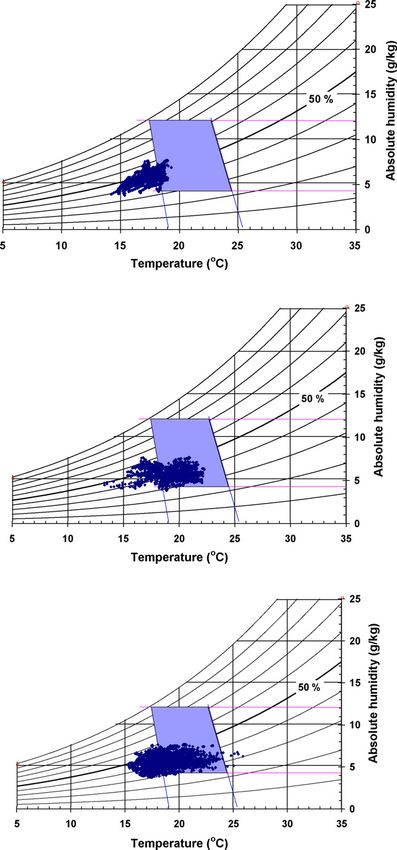
794                                               P. Taylor et al. / Energy and Buildings 40 (2008) 793–800

 Fig. 1. Northern aspect of rammed earth office building (right of figure).

2. Building description                                                           Fig. 3. Cross section through the building showing night ventilation path.

   The CSU office building contrasts sharply with a typical
office building in almost every feature (Fig. 1). It is a two-                   conceal duct work, and the concrete ceilings are exposed. In
storey building with load bearing rammed earth external and                      some places, a corrugated profile has been cast into the ceiling
internal walls and there is no steel frame. The windows open to                  to increase its surface area to enhance convective heat transfer.
permit natural ventilation. The building is curved and                           The floors are carpeted.
orientated as shown in Fig. 2. There is a central corridor                           The windows are single 6 mm glass with wooden frames.
running the length of the building on both levels with offices on                The offices have double hung vertically sliding sash windows
either side. Each office is typically 10.5 m2 in floor area. The                 with weather strip sealing. In the stair wells and at the end of the
circles in Fig. 2 are rainwater tanks. The ellipses are voids                    corridors upstairs there are manually operated louvre windows.
between the ground floor and upper storey giving a light and                     Window shading has been carefully designed to exclude all
ventilation well. Ventilation towers or stacks are situated above                direct beam sunlight during the summer months. Each office
these wells.                                                                     has a variable speed sweep fan controlled by the occupier and
   Hydronic heating and cooling has been installed instead of                    these fans are seen as an important cooling mechanism. The
an HVAC system and there are circulation pipes embedded in                       building has woollen insulation placed underneath the roof
the ground floor slab and the two ceiling slabs. Ninety-eight                    sheeting rather than on top of the upper ceiling slab. Solid-foam
square metres of flat plate solar collectors have also been                      insulation was installed around the edge of the concrete slabs.
installed on the roof of the building. It was anticipated                        The external doors at CSU all close automatically and seal
that these panels would collect sufficient energy in winter to                   against a wooden frame.
significantly reduce gas consumption. By circulating
water through the panels at night in summer, it was also                         3. Climate
expected that radiant cooling would produce a store of cold
water to reduce cooling energy requirements on the                                  The region is characterised by long-hot summers and cool/
following day.                                                                   cold-wet winters, typical of a Mediterranean climate. The mean
   Cooling is also achieved through using a night ventilation                    maximum temperature in January is 31.8 8C and the mean
purge in summer (Fig. 3). Fresh air is allowed to circulate in                   minimum in July is 3.1 8C [2]. There is a large diurnal variation
through the louvres located under the office windows and out                     between maximum and minimum temperatures. On average in
through the louvres in chimney ventilation stacks. These sets of                 January, the diurnal swing is 16.6 8C, while in July it is 9.5 8C.
louvres are computer controlled, whilst the louvres above the                    In January, the mean daily average temperature is 23.5 8C. In
office doors may be only operated manually. Since a hydronic                     summer, on average there are 16.6 days when the maximum
system is used, there is no need for a suspended ceiling to                      temperature is expected to be over 35 8C, while in winter there
                                                                                 are 31.9 days with a minimum temperature below 2 8C (Fig. 4).
                                                                                 Furthermore the daily maximum temperature is below 20 8C for
                                                                                 5 months of the year.
                                                                                    In this area of inland Australia the relative humidity in
                                                                                 summer is between 30 and 50%. As expected, the skies are less
                                                                                 cloudy in summer with an expectation of 10 h sunshine per day,
                                                                                 while in winter on average there are 4.5 h of sunshine per day.
                                                                                 The global irradiation on a clear day in summer may reach
Fig. 2. Schematic plan view of second storey of rammed earth office building.    30 MJ/m2.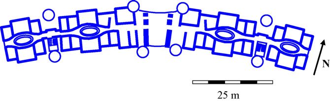
P. Taylor et al. / Energy and Buildings 40 (2008) 793–800                                   795

                                                                              working environment of their office; this was intended as a
                                                                              general satisfaction question. Section C elicited information on
                                                                              the thermal adaptive strategies of respondents: the use of fans,
                                                                              lights, blinds, and windows and concluded with a series of open
                                                                              questions specifically concerning comfort. Full details of the
                                                                              questionnaire used are available in [6].
                                                                                 An alternative way of measuring thermal comfort is to use
                                                                              one of the various models developed to describe this
                                                                              sensation and then calculate the fraction of occupancy time
                                                                              when these conditions are met by a particular building. The
                                                                              adaptive model of [7] was considered to be most appropriate
                                                                              to a naturally ventilated building such as CSU, where
            Fig. 4. Local pattern of extreme weather days.                    occupants have some control over their environment. Having
                                                                              established the neutral indoor operative temperature (‘neu-
4. Methodology                                                                trality’) using [7], the summer and winter comfort zone for
                                                                              the location was constructed using the method described by
    The office has been designed in accordance with a set of                  Auliciems and Szokolay [8]. Various measured physical
environmental principles, established prior to the development                parameters were used to indicate the percentage of time
of the Thurgoona Campus. The principles are divided into three                during working hours the indoor conditions in three offices
categories; namely low energy, resource management and                        fell within these comfort zones at those times of the year. The
environmental impact [3]. The low energy principle sought to                  internal and external surface heat fluxes of selected external
maximize the passive use of the building ‘‘to collect, store and              walls were measured with heat flux transducers (International
distribute energy’’, while one of the resource management                     Thermal Instruments, Model A). Various temperatures in the
principles was ‘‘to maximize the comfort of the building                      offices, namely: at several heights, globe, wet bulb, wall
users’’. It was therefore appropriate to choose performance                   surface and mid-wall were measured with thermistors
indicators which were consistent with these design principles.                (Betatherm, 10K3A1IA). Reed switches recorded fan rotation
The two indicators of performance used in this study are                      and window status. Data loggers (Campbell Scientific,
thermal comfort and energy use. In general, a building that                   CRX10) stored averaged data at 15 min intervals and a
consumes a relatively small amount of energy in its operation                 weather station (Davies Weather Monitor) collected climatic
should be inexpensive to run and will have low CO2 emissions,                 data. Full details of measurements and instrumentation have
an important environmental consideration. Some of the energy                  been previously reported [9].
used in a building is for the benefit of the occupants to make                   Both of the above methods were used to examine the thermal
them comfortable and therefore productive, but while energy                   comfort performance of the CSU offices.
reduction is important, it must not be at the expense of thermal
comfort. The measurement methodology for these two                            4.2. Energy use
indicators is discussed below.
                                                                                 The energy use and greenhouse gas emissions of the
4.1. Thermal comfort                                                          Academic Offices Building were compared with another CSU-
                                                                              owned building at the same location, also used for office
   Thermal comfort is a subjective measurement. Thermal                       accommodation and a library. Known as the ‘Gordon Beaven
comfort is defined by [4] as ‘‘that condition of mind that                    building’ and constructed in 1987, this building has three split-
expresses satisfaction with the thermal environment’’. One way                level storeys and is constructed with concrete blocks within a
to gauge thermal comfort levels is simply to ask building                     concrete beam frame. The building is fully air-conditioned and
occupants how they experience a building in terms of their                    maintained in good order. Most of the buildings on the CSU
temperature sensations. A number of scales have been                          Thurgoona Campus have their own gas and electricity meters
developed to do this. The survey questions used in this study                 that are read by the maintenance staff on a weekly basis.
were in part taken from the questionnaire developed by                        Monthly accounts from utility companies are also available.
Levermore et al. [5]. However, because an adaptive model was                  Gas and electricity use in the Academic Offices Building was
used to evaluate the building (see below), further questions                  established directly for 2001 from the meter readings.
were added.                                                                   Comparable data for the Gordon Beaven Building was obtained
   The final questionnaire therefore consisted of three sections.             indirectly by subtracting the energy consumed by the newer
Section A requested background information from respondents                   buildings on site from the overall figure read from the main site
(age, sex, type of work, and amount of time spent on leave over               meter. Using Australian industry guidelines [10], the useable
the summer period). Section B asked a number of multiple-                     area of both buildings was established either from plans
choice questions (on a seven-point scale) to guage a                          (Academic Offices) or from a list of room sizes (Gordon
respondent’s perception of their room with regard to aesthetics               Beaven), and was calculated to be 1500 and 2186 m2
and comfort. Section B also asked respondents to rate the                     respectively.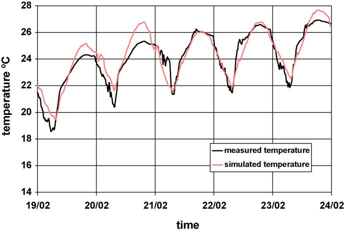
796                                             P. Taylor et al. / Energy and Buildings 40 (2008) 793–800

5. Results

   Thermal comfort during summer in three offices of the
Academic Offices Building was investigated over a 28-day
period from 13 February to 13 March 2001. Ambient
temperatures varied from a minimum of 6.7 8C to a
maximum of 36.9 8C with an average of 22.7 8C. Fig. 5
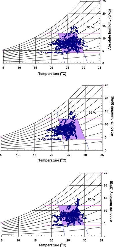
shows the coincidence of the measured psychrometric data
and the comfort zones for the three offices and Table 1
presents a summary of the operative temperatures and
percentage of time in the summer comfort zone in same three
locations.
   The ground floor office (office A) located on the southeast
corner of the building was clearly performing better than the
other two offices. Its average temperature was 23.7 8C and was
above 25.4 8C for 25% of the time. It was in the comfort zone
for 73% of the time, but this was because the office was too
cold, rather that too hot. This office was rarely used and
therefore had a very low internal heat load. The two upper level
offices were on average 1–2 8C warmer than the ground floor
office. Office C located on the northwest corner of the building
had a median temperature 1.3 8C higher than office B (mid
north side), although office B experienced a wider range of
temperatures. This was probably because the window of office
B was open for 22% of the time, whilst the window of office C
was never opened. Offices B and C both recorded temperatures
outside the upper and lower limits of the comfort zone. The
75% percentiles for offices B and C were 26.5 and 27.2 8C,
respectively. Whilst offices B and C are within the comfort zone
for longer periods than office A, it is unlikely that people would
complain about office A being too cold during the summer
months, while it is highly probable that offices B and C would
be experienced as uncomfortably warm.
   Thermal comfort during winter conditions was analysed
over the 38-day period between 30 June and 4 August 2001
(Table 2). The average ambient temperature was 8.1 8C. For
75% of the time the temperature was below 11.1 8C i.e. 7 8C
below the lower limit of the comfort zone. Unlike the summer
conditions, the winter ambient temperature was always below
comfort temperatures. Since the offices were not specifically
designed for direct solar gain in the winter, thermal comfort was
to be achieved by the hydronic heating system. The
psychrometric analysis shown in Fig. 6 demonstrates the                        Fig. 5. Coincidence of measured psychrometric data with summer comfort
effectiveness of this strategy.                                                zone for offices A–C during occupied hours.
   Fig. 6 indicates that the heating system often failed to
provide thermal comfort, particularly in office A, where

Table 1
Operative temperatures in offices A–C in selected summer period during occupied hours
Temperatures (8C)                   Ambient                   Operative office A                   Operative office B               Operative office C
Mean                                23.1                      23.7                                 24.7                             25.8
Minimum                             6.7                       16.4                                 15.9                             20.1
25% percentile                      18.9                      22.4                                 23.0                             24.7
Median                              22.7                      24.1                                 25.0                             26.3
75% percentile                      27.3                      25.4                                 26.5                             27.2
Maximum                             36.9                      27.4                                 31.0                             30.3
Comfort zone (%)                    n.a.                      73                                   76                               81
P. Taylor et al. / Energy and Buildings 40 (2008) 793–800                                                   797

                                                                                    Table 3
                                                                                    Energy use and intensity for two CSU buildings in 2001
                                                                                    Building           Energy use (GJ)              Area Energy intensity (MJ/m2)
                                                                                                                                    (m2)
                                                                                                       Electricity Gas        Total      Electricity Gas Total
                                                                                    Gordon Beaven    1548             567 2114 2186 708                 259   967
                                                                                    Academic Offices 246             1024 1270 1500 164                 683   847

                                                                                    Table 4
                                                                                    Greenhouse gas emissions two CSU buildings in 2001
                                                                                                            Electricity         Gas                  Total
                                                                                                            (CO2 ! e kg/m2)     (CO2 ! e kg/m2)      (CO2 ! e kg/m2)
                                                                                    Gordon Beaven           207                 13                   220
                                                                                    Academic Offices         48                 35                    83

                                                                                    Table 5
                                                                                    Summary of climatic data during model validation periods
                                                                                                                          Summer                              Winter
                                                                                    Ambient temperature (8C)
                                                                                     Minimum                                   14.8                           !0.9
                                                                                     Average                                   25.4                            6.8
                                                                                     Maximum                                   36.3                           14.7
                                                                                    Horizontal radiation (W/m2)
                                                                                      Maximum                             1118                                592

                                                                                    thermal comfort zone was achieved for only 13% of the time.
                                                                                    Subsequent investigations indicated that the heating system was
                                                                                    not working correctly in office A. The median temperatures in
                                                                                    the top floor offices were 18.7 and 18.8 8C, approximately
                                                                                    1.8 8C higher than the ground floor office and only just within
                                                                                    the comfort zone. A small electric heater was occasionally used
                                                                                    in office C, while some of the cooler temperatures in office B
                                                                                    are likely to have been due to an open window. Since the offices
                                                                                    are naturally ventilated the only way to obtain fresh air in winter
                                                                                    (apart from infiltration) was to open the window. Office A never
                                                                                    reached 20 8C, while the remaining offices exceeded 19.7 8C
                                                                                    for 25% of the time. Therefore these offices would probably
                                                                                    have been perceived as ‘just comfortable’ to a well-clothed
                                                                                    occupant, but would not have been considered warm. Some
Fig. 6. Coincidence of measured psychrometric data with winter comfort zones        anecdotal evidence indicates that other parts of the Academic
for offices A–C during occupied hours.

Table 2
Operative temperatures in offices A–C in selected winter period during occupied hours
Temperatures (8C)                  Ambient                     Operative temperature                 Operative temperature                   Operative temperature
                                   temperature                 in office A                           in office B                             in office C
Mean                               8.1                         16.9                                  18.6                                    19.0
Minimum                            !0.9                        14.1                                  12.6                                    15.6
25% percentile                     5.1                         16.2                                  17.5                                    17.9
Median                             8.2                         17.0                                  18.8                                    18.7
75% percentile                     11.1                        17.6                                  19.7                                    19.7
Maximum                            17.4                        19.2                                  22.2                                    28.1a
Comfort zone (%)                   n.a.                        13                                    69                                      70
 a
     It is believed that this high temperature was caused by late afternoon direct sunlight falling on the measuring equipment.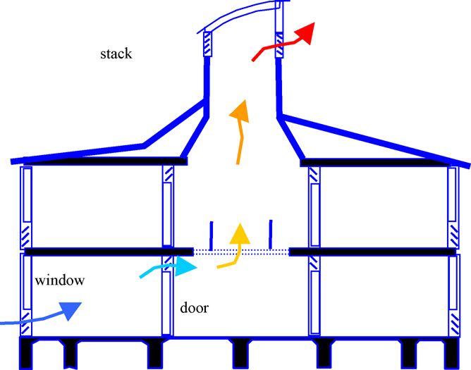
798                                              P. Taylor et al. / Energy and Buildings 40 (2008) 793–800

Table 6
General dimensional and operational parameters used in simulations

Office Building were appreciably warmer than these offices                      6. Discussion
during the winter.
   The energy intensity used to achieve this level of comfort                      The average energy intensity for Australian offices is
and the associated greenhouse gas emissions are shown in                        reported to be 981 " 62 MJ/m2 p.a. [11] and the Australian
Tables 3 and 4, respectively.                                                   Building Codes Board (ABCB) design target for new buildings
P. Taylor et al. / Energy and Buildings 40 (2008) 793–800                                                799

in the Albury-Wodonga region is 640 MJ/m2 p.a. [12]. In terms
of total energy use, the Gordon Beaven building is very close to
the Australian average, whilst the Academic Office Building
uses 13% less than the average. However, since the latter is a
relatively new building with a ‘green’ reputation, a reasonable
expectation would be that it would use less significantly less
energy than the ABCB target. In reality, however, it exceeds this
target by over 30%. It appears that the installation of the solar
collection system in the Academic Offices has not achieved any
reduction in heating energy use compared to a conventional
system. The absence of an electrically-driven refrigerative
cooling system has resulted in a building that uses only one fifth
of the electrical energy of the more conventional building;
however, it does not meet comfort standards all the time.
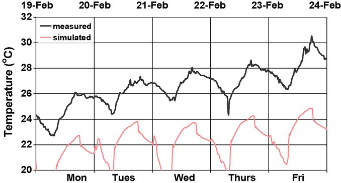
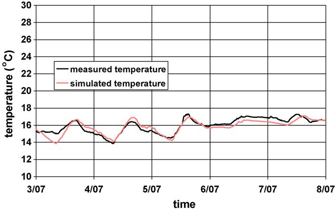
    Table 3 also shows that gas and electricity usage in the two                Fig. 7. Measured and predicted temperatures in office C in summer.
buildings is significantly different. The Gordon Beaven
building consumes more than twice as much electricity as
gas, whilst the Academic Offices Building use four times as                 when the two temperatures became equal. Since the ventilation
much gas as electricity. As a result, total greenhouse gas                  rate could not be measured directly, the value used was chosen
emissions for the former building are almost three times those              to obtain a match between measured and simulated results.
of the latter ‘‘deep green’’ building (Table 4).                            Office air temperatures, measured at 1.1 m above floor level,
                                                                            were used to validate the predictions of the summer and winter
7. Simulation                                                               models (Figs. 7 and 8). Agreement between measured and
                                                                            predicted values was considered adequate to use the models to
   The above analysis indicates that Academic Office Building               investigate improvements to the CSU building.
is not performing well. TRNSYS models were therefore                           Three strategies were investigated to reduce the office
developed to investigate the effect of changes to the control               temperatures in summer. The strategies were (a) increasing the
system or to the building fabric on the energy use and thermal              night ventilation rate; (b) adding insulation to the external walls
comfort provided by the building. The first model described the             and ceiling; and finally (c) using a hydronic cooling system.
top-floor office C and explored a number of options to improve              Their effect was not investigated separately; rather the
thermal comfort during the summer. The second model was                     cumulative effect of the strategies was predicted. Progressive
used to investigate the energy consumption in the ground floor              predictions have been reported elsewhere [13]. The predicted
office A in both summer and winter. Five days were selected in              effect of all three strategies combined is shown in Fig. 9,
both summer and in winter over which time to validate and run               compared against the measured temperatures in Fig. 7, and
the models. The period in summer had clear sunny days with the              statistical impact on operative temperatures is given in Table 8.
maximum temperature of 36.3 8C. The winter period was                       The operative temperature is now below the lower limit of the
considered typical of that time of year. There were three sunny             ASHRAE comfort zone for 75% of the time, although it would
days with cold nights followed by two cloudy days. Table 5                  probably be very acceptable by Australian standards.
summarises the climatic data during the modelling periods.                     The validated model of office A was used to try to investigate
   The general office dimensional and operational parameters                two strategies, namely wall insulation and a combination of
initially used in the simulations are given in Table 6, while               insulation, glazing and reduced infiltration, to reduce the
material parameters used are given in Table 7. The variable vent
can take values of 0 or 1. The latter indicates the use of night
purging, while a zero indicates the contrary. Ventilation of the
office occurred when the external air temperature fell 2 8C
below the average internal building air temperature, and ceased

Table 7
Material parameters
Parameter                            Value                    Unit
Internal film conductance            8.3                      W/m2 K
External film conductance            3.9 V + 5.62             W/m2 K
Wall surface solar absorptance       0.6                      n.a.
Density of rammed earth              2050                     kg/m 3
Rammed earth conductivity            1.0                      W/m K
Specific heat of rammed earth        600                      J/kg K
Carpet R-value                       0.22                     m2 K/W
                                                                                 Fig. 8. Measured and predicted temperatures in office A in winter.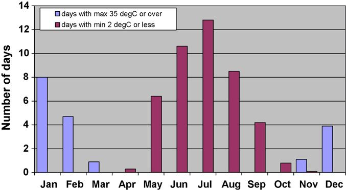
800                                                P. Taylor et al. / Energy and Buildings 40 (2008) 793–800

                                                                                    Board although the low electricity use does give low-
                                                                                    greenhouse gas intensity. It is clear that the installed solar
                                                                                    system did not perform as intended. Thermal comfort was not
                                                                                    adequately achieved during occupied hours. In the summer
                                                                                    evaluation period, two out of the three offices measured had
                                                                                    operative temperatures outside the comfort zone for over 20%
                                                                                    of the time. In the winter, the situation was worse with the two
                                                                                    top floor offices providing thermal comfort for only 70% of the
                                                                                    time and the ground floor office for only 13% of the time.
                                                                                        The computer modelling has indicated the value of increasing
                                                                                    the R-value of the external walls by external insulation. Model
                                                                                    validation indicated that there was a relatively high infiltration
Fig. 9. Predicted combined effect of increased night ventilation, additional
insulation and hydronic cooling on air temperatures in office C.                    rate. This unwanted air exchange lead to cool internal
                                                                                    temperatures in the winter. However, in the summer the required
                                                                                    air exchange used for the night purging has been shown to be too
Table 8                                                                             low to cool the building for daytime use. Wall conduction rate,
Effect of strategies on office C air temperatures in summer                         infiltration and night purging are all examples of systems that
Statistic            Measured (8C)         Predicted (8C)        Operative (8C)     allow, either intentionally or unintentionally, heat to be
Minimum              23.0                  18.5                  18.8               transferred between the building and its surrounds. A key aspect
25% percentile       25.8                  22.3                  22.0               in the design of a ‘low energy’ building is the control of this type
Median               26.7                  23.2                  22.9               of heat exchange so that a large input of heat is not required in the
75% percentile       27.7                  23.8                  23.4               winter and the building does not overheat in summer. The results
Maximum              30.5                  24.9                  24.4
                                                                                    of the thermal modelling have shown how to manage the heat
                                                                                    flows so that the building performs better.
Table 9
Energy flows, peak loads and heating energy requirements for existing and
modified east-facing external wall in winter                                        References
Variable                        Existing     Insulated      Insulated wall +
                                wall         wall           insulated slab +         [1] L. Johnson, The view from Australia—green limits in the land of plenty,
                                                            low-E window +               Architectural Design 71 (4) (2001) 52–59.
                                                             reduced infiltration    [2] Bureau of Meteorology, http://www.bom.gov.au/climate/averages/tables/
                                                                                         cw_082056.shtml viewed July 28, 2003.
Heat from external wall (MJ)    !121.4       !26.2          !31.2
                                                                                     [3] Webster-Mannison, M. Charles Sturt University, Thurgoona Campus,
Peak heating load (kW)             3.0         2.5            1.0
                                                                                         New South Wales, Australia. Alternative Construction. Contemporary
Total heating energy (MJ)        390.5       249.0           62.3
                                                                                         Natural Building Methods, in: L. Elizabeth, C.Adams (Eds.), Wiley and
                                                                                         Sons, New Jersey, 2005, (Chapter 2).
                                                                                     [4] American Society of Heating, Refrigerating and Air-conditioning Engi-
heating energy and improve thermal comfort in winter. The                                neers Inc., ASHRAE 55—Thermal Environmental Conditions for Human
hydronic heating in the ceiling was switched off for the study so                        Occupancy, Atlanta, GA (2004).
that the model could predict the mechanical heating required.                        [5] G.J. Levermore, D. Lowe, J. Ure, Occupant feedback questionnaire
Under these conditions, 390.5 MJ was needed to heat the office                           producing a fingerprint and a score, ASHRAE Transactions 105 (2)
                                                                                         (1999) 661–670.
for the entire 5 days, with a peak requirement of 3 kW (Table 9).                    [6] P. Taylor, Energy Use and Thermal Comfort in a Rammed Earth Office
Almost one third of this energy (121.4 MJ) was lost through the                          Building, Thesis for M. Architecture, Deakin University, Geelong, Vic.,
external wall (indicated by a negative heat flow).                                       Australia.
   External wall insulation alone reduced the heating require-                       [7] R. de Dear, G.S. Brager, Developing an adaptive model of thermal comfort
ment in winter to 249 MJ, with the heat lost through the external                        and preferences, ASHRAE Transactions 104 (1a) (1998) 145–167.
                                                                                     [8] A. Auliciems, S.V. Szokolay, Thermal Comfort, Design Tools and
wall reduced by 78%. If other energy savings measures e.g. floor                         Techniques, Passive and Low Energy Architecture International, in
insulation, low-E glazing, etc. had also been adopted, even greater                      Association with Department of Architecture, University of Queensland,
energy savings could have been achieved (Table 9). Although the                          Brisbane, Qld, 1997.
simulations indicate that the heat lost to the external wall would                   [9] P. Taylor, M.B. Luther, Evaluating rammed earth walls: a case study, Solar
increase slightly because the office was warmer, the heating                             Energy 76 (1–3) (2004) 79–84.
                                                                                    [10] Property Council of Australia, Method of Measurement for Lettable Area.
demand has dropped to only one sixth of its original value. No                           Sydney, Australia, 1997.
heating is required at night to maintain the required temperature,                  [11] P. Bannister, Australian Building Codes Board: Class 5 Benchmarking,
as the office air temperature did not fall below 18 8C.                                  Exergy Australia Pvt. Ltd., Belconnen, ACT, Australia, 2004.
                                                                                    [12] Australian Building Codes Board, Building Code of Australia, vol. 1,
8. Conclusions                                                                           Section J, Canberra, ACT, Australia, 2006.
                                                                                    [13] P. Taylor, R.J. Fuller, M.B. Luther, in: Proceedings of the Solar 2004
                                                                                         Annual Conference of Australian and New Zealand Solar Energy Society
   The building has been shown to have larger energy intensity                           on Validated Model and Study of a Rammed Earth Wall Building,
than the target specified by the Australian Building Codes                               Murdoch University, Perth, WA, December 1–3, 2004.
You can also read


