Comparison of UV and EB Technology for Printing
←
→
Page content transcription
If your browser does not render page correctly, please read the page content below

Technical Paper
Comparison of UV and EB
Technology for Printing
and Packaging Applications
                            U
By Stephen C. Lapin                   V/EB curing technology for           high energy required to remove water
                                     inks, coatings and laminating         from the solids portion of the formula.
                                     adhesives has become well             This high-energy requirement for water
                            established in certain segments of the         is illustrated by comparing the heat of
                            packaging industry—including folding           vaporization to some common solvents2:
                            cartons, labels and multiwall bags.                 water = 540 calories/gram
                            There is also growing interest in UV/EB             toluene = 88
                            technology for flexible packaging.1 The             heptane = 76
                            growth in UV/EB applications is due, in             The generation of energy needed to
                            part, from the inherent advantages over        operate the driers to remove water
                            solvent- and water-based materials.            results in significant CO2 emissions. In
                               The solvent in conventional inks,           addition, most water-based materials
                            coatings and adhesives functions               do contain some solvents to aid the
                            simply as the “carrier” for the “solids”       formation of the polymer film upon
                                                                           drying the ink, coating or adhesive. Also,
A clear understanding of the differences between                           in many cases, water-based materials do
                                                                           not have the resistance or appearance
UV and EB can facilitate a selection of which                              properties to match higher performance
technology is best suited to the end-use application.                      solvent- or UV/EB-based materials.
                                                                                In spite of the clear advantages of
                            portion of the material. In most cases,        UV/EB technology over solvent and
                            solvent emissions are handled by               water-based technology, there is often
                            thermal oxidation which produces               some confusion as to whether UV or
                            greenhouse gas (CO2). Solvents are             EB is a better choice. A clear
                            highly refined materials derived from          understanding of the differences
                            fossil hydrocarbon sources. It is quite        between UV and EB can facilitate a
                            wasteful to use such a high-value              selection of which technology is best
                            material for such a low-value temporary        suited to the end-use application.
                            function. Solvent-based materials are
                            old technology that is clearly out of      º   UV and EB Energy
                            step with a sustainable future.                Considerations
                               At first glance, water-based inks,              There are some fundamental
                            coatings and adhesives would appear            differences between UV and EB energy
                            to be an excellent choice from an              that provide the foundation for
                            environmental perspective. Water is a          understanding the technologies. The
                            relatively plentiful, low-cost and             smallest “bit” of UV energy is the
                            environmentally friendly carrier. The          photon that is known to have both
                            main disadvantage with water is the            particle and wave-like characteristics.

                                                             SEPTEMBER/OCTOBER 2008 RADTECH REPORT 27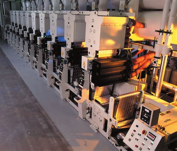
Technical Paper

                  The energy for photons is determined      with the media to be cured. The typical     substrate, it is possible to make a
                  by the wavelength. The range of           chemical bond energy in an organic          direct comparison of the total applied
                  wavelengths for UV curing applications    material that is the basis of an ink,       energy in UV- and EB-curing
                  is typically about 250 to 450 nm. The     coating or adhesive is on the order of      processes. A typical modern low-
                  shorter the wavelength, the higher the    5 eV. Curing reactions are initiated with   voltage EB unit operating at 125 kV
                  energy. Wavelength units may be           the breaking of a chemical bond. Since      will penetrate into a 50 g/m2 layer.
                  converted to other energy units for       UV photons have less energy than the
                                                                                                        Thus, given 1 kGy = 1 J/gram, and
                  comparison. For example, a 350 nm         bond energy, they cannot initiate
                                                                                                        assuming a 50 gram/m2 substrate,
                  photon is equivalent to 3.5 electron      curing on their own. A photoinitiator is
                                                                                                        then; 20 to 40 kGy = 0.1 to 0.2 J/cm2
                  volts (eV). UVcuring processes are        needed which can be activated by the
                                                                                                        for typical EB curing compared to:
                  often characterized by the total          lower energy photons. The energy of
                                                                                                        0.1 to 0.5 J/cm2 for typical UV curing.
                  amount of applied UV energy               the EB electrons easily exceeds the
                  impinging per unit surface area (also     bond energy of the curable materials;          The lesson from this exercise in
                  known as the irradiance). The UV          thus they will initiate curing without an   energy unit conversions is that
                  energy needed for a curing process        added photoinitiator. EB is also known      although EB electrons are much more
                  depends on the material and the           as ionizing radiation because of its        energetic than UV photons, the total
                  application. For an ink, coating or       ability to break chemical bonds. UV is      amount of energy applied in a typical
                  adhesive for a packaging application,     non-ionizing radiation.                     curing process is not all that different.
                  the UV energy typically ranges from           In addition to considering the
                  about 0.1 to 0.5 J/cm.2                   energy of the individual photons and        UV and EB Penetration
                      The smallest “bit” of EB energy is    electrons, it is useful to compare the          The nature of the energy determines
                  the electron. The energy of the           total energy applied in the curing          how it penetrates into a material.
                  electrons is determined by the            process. As can be seen from the            Curing can only occur in areas that
                  accelerating potential of the EB          discussion above, UV curing is              are effectively exposed. Figure 1
                  equipment. The range of accelerating      characterized by the energy absorbed        provides a cross-sectional illustration
                  potential used for typical packaging      per unit area (irradiance), while EB        of the differences between UV and
                  applications is about 80 to 180 kV. The   curing is characterized by the energy       EB penetration.
                  electrons lose some energy when           per unit mass (dose). If one considers          Penetration of UV energy depends
                  passing through the foil window and       a given thickness and density of the        on the optical density (OD) of the
                  the air space between the window and
                  the substrate. For example, the
                  electrons from an EB unit operating at     Figure 1
                  100 kV have an average energy of
                  about 70 keV when they reach the              Penetration of UV and EB energy
                  substrate. EB curing processes are
                  often characterized by the total
                  amount of energy absorbed per unit
                  mass of the substrate (also known as
                  the cure dose). The dose for EB curing
                  depends on the material and the
                  application. For an ink, coating or
                  adhesive for a packaging application,
                  the cure dose typically ranges from
                  about 20 to 40 kGy (2 to 4 Mrads).
                      It is interesting to compare the
                  energy of a typical UV photon (3.5 eV)
                  to an EB electron (70,000 eV). Clearly,
                  EB electrons are much more energetic
                  than UV photons. This has a significant
                  impact on how this energy interacts

                  28 RADTECH REPORT SEPTEMBER/OCTOBER 2008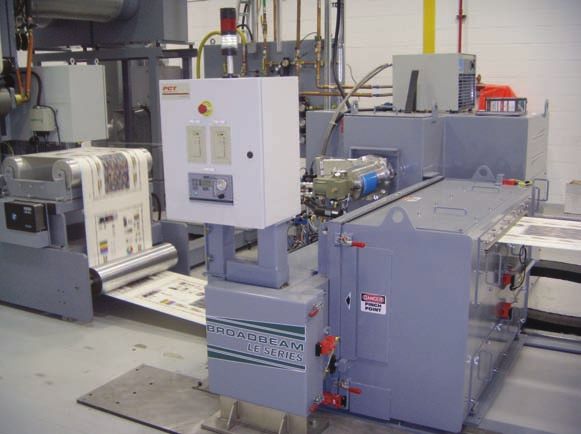
Technical Paper
material. Clear materials are “optically
thin.” In general, UV energy can easily      Figure 2
penetrate clear materials such as
overprint coatings and clear films.             Depth/dose profiles for low-voltage EB
Even if a portion of the UV spectrum is
blocked by a clear layer (such as a PET
film), effective curing can usually be
achieved throughout the thickness of
the layer by selecting the proper
photoinitiator package. Penetration of
UV energy becomes a significant
challenge when curing “optically thick”
pigmented materials. Many pigmented
printing inks can be UV cured as long
as the pigment loading and/or ink
thicknesses remain relatively low. It is
typically difficult to UV cure through
printed, white opaque, heavy black or
metallic inks.3
    Penetration of UV energy can be
controlled, to a degree, by the peak           EB penetration is controlled by the      quite limited in printing and packaging
irradiance of the lamp. The peak            accelerating potential (voltage) of the     materials.7
irradiance depends on the power and         EB equipment. Figure 2 shows EB                 EB equipment is based on electrically
the focus of the lamp system. High-         penetration as a function of voltage.       operated filaments and grids contained
power, tightly focused lamps can            Low-voltage EB equipment operating          within a vacuum chamber. The
improve curing of some higher OD ink        from about 70 to 125 kV is ideal for        electrons are accelerated through a
layers4; however, the OD can reach a        curing thin inks, coatings and film         window/foil structure to reach the
point in which curing is not possible       layers used in most printing and            substrate at atmospheric pressure.
with any commercial lamp system.            packaging applications.6                    EB equipment includes “curtain” and
   EB penetration depends upon the                                                      scanning type units. The curtain type
mass density and thickness of the           UV and EB Equipment                         is used almost exclusively for printing
material. Electrons penetrate more              The most common UV equipment            and packaging applications. Most EB
deeply through lower density materials      for printing and packaging applications     equipment includes an active pumping
(such as polyolefin films and paper)        is based on medium-pressure mercury         system to maintain a vacuum in the
compared to high-density materials          lamps. These lamps may be energized         electron gun chamber. A new
such as metal foils. Mass density and       through electrodes (arc type) or by         generation of modular 10- and 16-inch
thickness taken together may be             microwaves (electrodeless). Medium-         wide EB equipment based on
expressed as the basis weight of the        pressure mercury lamps produce a            permanent vacuum emitters is also
material. For most printing and             characteristic UV-emission spectrum         now available. There have been some
packaging applications, the basis           with multiple peaks between 250 nm to       initial investigations incorporating
weight is expressed in units of grams/      450 nm. Mercury lamps may also be           these modular emitters in printing
meter 2 or pounds/3000 ft2. Electrons       doped with various elements to shift the    applications.8
are “color blind” and penetration is not    spectral output to better match the inks,
affected by pigments and opaque             coating or adhesive that is being cured.    UV and EB Equipment Safety
substrates. EB is ideal for curing high-        Other types of lamps, such as              UV lamps used in printing and
opacity white, black and metallic ink       xenon lamps, are available but are not      packaging applications produce
layers. EB can also penetrate reverse       commonly used for printing and              significant short wavelength UV
printed, metalized and white films as       packaging applications. UV-light emitting   output. This intense UV energy can
well as papers to instantly cure adhesive   diodes (LEDs) are now available with        cause skin and eye damage.
layers for laminating applications.5        higher powers, but their use is still       Commercial UV lamp equipment used

                                                                             SEPTEMBER/OCTOBER 2008 RADTECH REPORT 29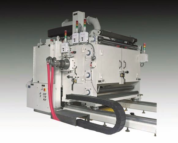
Technical Paper

                  for printing and packaging applications   management components) is relatively         of the press with a single EB unit. The
                  is completely shielded and interlocked    compact and lends itself well to             development of modern low-voltage
                  to contain the damaging UV energy. In     interstation installation between            EB equipment coincides nicely with
                  most cases, no special personal           printing decks (Figure 4). Interstation      the development of web offset presses
                  protective equipment (PPE) is             installation allows curing of each ink       incorporating variable repeat length
                  required other than the PPE normally      color. Multiple colors are combined in a     technology. This has facilitated
                  recommended in the printing and           “dry trapping” process to create the         expansion of web-offset printing
                  packing production plant environment.     graphic image. Interstation curing also      technology beyond folding cartons to
                  In addition to UV energy hazards,         allows press designs in which the            flexible packaging and labels.10
                  mercury lamps also operate at very high   printed side of the web may be turned             Flexographic printing utilizes liquid
                  temperatures. Hazards from thermal        up against an idler roll between stations.   inks so, historically, it has been necessary
                  skin burns are minimized by the lamp          Original industrial EB equipment         to use interstation curing to dry trap
                  housing which surrounds the bulb.         was quite large (Figure 5). Modern           inks. This interstation curing has been
                      Electrons from EB equipment           low-voltage EB equipment can be less         achieved by thermal or UV curing
                  present limited hazards because of        than one-half the size of original           technology. Recently new technology
                  their limited ability to penetrate. The   industrial EB equipment. In spite of         (Wetflex™) has been developed to wet
                  main hazard of EB is the secondary        the size reduction, it is still not          trap flexographic inks.11 Wet trapping
                  X-rays that are generated when            practical to use this equipment for          allows interstation curing to be
                  electrons interact with matter,           interstation curing; though the smaller      eliminated and replaced with a single EB
                  including metal components within the     footprint is still very attractive for       curing station at the end of the press
                  EB reaction chamber. Modern EB            end-of-press installations.9 The most        (Figure 7). This technology has also
                  equipment is completely self-shielded.    common installation of this type of          been shown to give extremely low dot
                  The shielding is interlocked and          equipment is at the end of a web offset      gain which results in superior quality
                  monitors are present which will shut      press used for the production of             printing. It should be noted that Wetflex
                  down the EB unit if X-rays are            folding cartons (Figure 6). Offset           is limited to central impression (CI) flexo
                  detected. Radiation is not present if     (lithographic) printing uses paste inks      press configurations in which the printed
                  the machine is not energized. Most EB     which are designed to be “wet trapped”       side of the web does not contact idler
                  installations will include a person       without any interstation drying. This        rolls until after EB curing. Flexographic
                  trained as a Radiation Safety Officer     lends itself well to EB curing at the end    CI printing is often the preferred
                  (RSO). Periodic radiation surveys are
                  typically conducted to supplement the
                  continuous monitoring of the equipment.
                  Worker exposures above normal
                                                             Figure 3
                  environmental background levels are
                  extremely rare.
                                                                 UV Lamp system components
                      Both UV and EB equipment are
                  very safe to operate and there are no
                  significant drivers for selection of
                  one technology over the other based
                  on safety.
                                                                              UV Lamp Cassette
                                                                                                                                              Photos courtesy of Mark Andy Inc.

                  Equipment Size
                     The components of typical UV
                  curing systems include the lamp,
                  power supply, air handling equipment
                  (blowers) and control panels. These
                  components are pictured in Figure 3.               Blower                                            Power Cabinet
                  The lamp (which includes the bulb,
                  reflectors, shielding and heat

                  30 RADTECH REPORT SEPTEMBER/OCTOBER 2008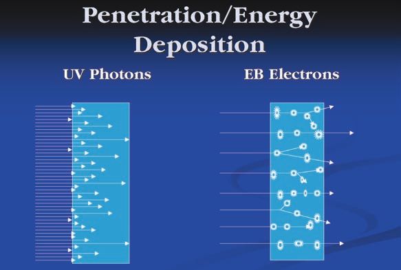
Technical Paper
                                                                                     multiple wet-trapped ink and coating
 Figure 4                                                                            layers may be cured with this single
                                                                                     unit. EB curing units are easily sized
    Interstation UV installation on a flexo press                                    for wide-web (>60 inches) printing
                                                                                     applications.
                                                                                        Even though a single UV lamp is
                                                                                     significantly lower in cost than an EB
                                                                                     unit, when one considers the total
                                                                                     capital cost of a wide, high-speed line,
                                                                                     EB may be comparable or lower in cost
                                                                                     than a multilamp UV installation.

                                                                                     Operating Costs
                                                                                        One of the primary advantages of UV
                                                                                     and EB curing is the reduced energy
                                                                                     costs compared to thermal drying
                                                                                     ovens.12 Another major component of
                                                                                     the operating expense is the cost of the
                                                                                     inks, coatings and adhesives. When
                                                                                     comparisons are made based on the
                                                                                     “solids” that are applied, it may be seen
                                                                                     that the cost of UV/EB materials
                                                                                     (which are near 100% solids) may not
                                                                                     command a significant premium.
                                                                                        In general, there does not tend to
method for flexible packaging since it      30 kGy (3 Mrad) cure dose at greater     be a significant difference in cost
provides superior handling of extensible    than 1,000 ft/min. As discussed above,   between UV and EB inks, coatings and
film substrates.
    New permanent vacuum modular             Figure 5
low-voltage equipment makes it
possible to consider interstation EB            Industrial EB processing equipment
curing. So far this does not appear to
be a commercial reality, but it is an
area for potential future development.

Capital Costs
    The cost of a UV lamp for a narrow
application is relatively low. For many
printing and packing applications, a
single lamp operating at input powers
up to 600 w/in will cure a single ink or
topcoat up to about 300 to 400 feet/
minute. Installation of six or more
press stations running at 800 to 1,000
ft/minute could require 12 or more lamps.
    Original industrial EB curing units
typically cost more than $1 million.
Modern low-voltage equipment has
reduced the cost by at least half. A
single EB unit is capable of delivering

                                                                            SEPTEMBER/OCTOBER 2008 RADTECH REPORT 31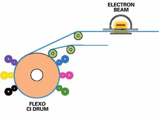
Technical Paper

                                                                                                      is inhibited by atmospheric oxygen.
                   Figure 6                                                                           Oxygen itself exists in a biradical
                                                                                                      (triplet) state and will rapidly diffuse
                      Low-voltage EB equipment on web offset press                                    into the surface of an ink or coating
                                                                                                      and terminate the polymerization
                                                                                                      (curing) reaction.
                                                                                                          UV formulations can be designed to
                                                                                                      cure in an air atmosphere. In air curing
                                                                                                      systems, the radical initiation
                                                                                                      essentially outcompetes the oxygen
                                                                                                      termination. This is possible because of
                                                                                                      the high surface irradiance illustrated
                                                                                                      in Figure 1. The ability to UV cure in
                                                                                                      air can be advantageous for some
                                                                                                      printing and packaging applications. In
                                                                                                      particular, air curing is very important
                                                                                                      in sheet-fed printing. Sheet-fed
                                                                                                      equipment is very difficult to inert
                                                                                                      because of the mechanisms present to
                                                                                                      transport the sheet through the press.
                                                                                                          In some cases, it may be advantageous
                                                                                                      to inert UV-cured systems. Inerting can
                  adhesives for printing and packaging         and significant savings compared to    greatly accelerate UV curing which can
                  applications. This may be due in part        thermal curing.                        increase line speed, reduce the number
                  to a declining cost of photoinitiators                                              of lamps, and/or reduce the amount of
                  following the expiration of some key         Inerting                               photoinitiator needed for curing.
                  patents. Comparison of UV and EB                Free radical curing—commonly        Inerting may be an attractive option for
                  operating costs is, therefore, more          used in both UV and EB applications—   food packing applications in which
                  related to the equipment itself.
                     With mercury-based UV lamps,
                  about one-half of the electrical energy       Figure 7
                  input is converted to UV energy. The
                  remaining energy is lost as heat. Some           WetFlex™ EB flexographic printing
                  additional electrical energy is consumed
                  in the operation of blowers for air
                  cooling which is most common for
                  printing and packaging applications.
                      EB equipment is more efficient at
                  converting electrical energy into curing
                  energy compared to UV equipment.
                  Some additional electrical energy is
                  needed for vacuum pumps and water
                  cooling of the emitter. Another
                  operating cost of EB is nitrogen, which
                  is needed to inert the curing zone for
                  most ink and coating applications.
                      A detailed comparison of operating
                  costs for UV and EB can be made for a
                  specific application. Often, this analysis
                  will show similar costs for UV and EB
                  32 RADTECH REPORT SEPTEMBER/OCTOBER 2008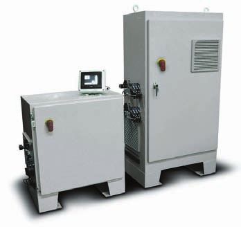
Technical Paper
migration of the photoinitiator and        inner (food contact) layer. This is        heat exposure. Most arc lamp-based
their fragments may be a concern.          particularly important when the inner      web systems include shutters to
    EB curing of free-radical inks and     layer is designed to be heat sealed when   prevent the web from burning when it
coatings requires inerting to displace     the packaged is filled and sealed.14       is stopped. Other strategies used to
the atmospheric oxygen in the reaction         In some cases where porous             minimize lamp heat effects on the
chamber of the cure unit. EB energy is     substrates (such as paper or cavitiated    substrates include dichroic reflectors,
deposited more evenly throughout the       films) are used, it can be advantageous    hot mirrors and chill drums.15
thickness of the ink and coating.          to use EB to cure materials which have         EB is a cooler process compared to
The absence of excess energy at the        penetrated into the substrate.             UV. Some internal components of the
surface does not allow curing reactions        EB’s effect on the substrate can be    EB emitter (including the window)
to compete with oxygen termination         beneficial. Cross-linking may enhance      utilize water cooling. Little heat is
(Figure 1).                                the properties of some polyethylene-       transferred to the substrate which
    EB laminating involves irradiation     based films. EB-induced ionization of      allows most packaging films to run
of the adhesive that is contained          the film surface may result in             without any effect on the dimensional
between two layers of substrate. EB        enhanced adhesion by grafting of the       stability of the film. A chill drum may
laminating does not require inerting       ink or coating layer. EB can also          be integrated into the EB unit for
because the substrates are generally
effective at preventing the diffusion of   In general, there does not tend to be a significant
oxygen into the adhesive layer.
    Inerting is most commonly achieved     difference in cost between UV and EB inks,
with nitrogen gas. Nitrogen serves to
                                           coatings and adhesives for printing and
displace oxygen from the reaction
chamber. The most common source of         packaging applications.
the nitrogen gas is a tank of liquid
nitrogen. The liquid offers the high-      potentially be used for simultaneous       applications that are very sensitive to
purity nitrogen and volume needed for      curing and surface sterilization of the    heat. In this configuration the
the curing process. Most modern EB         food contact layer.                        substrate is in direct contact with the
equipment is designed with nitrogen           Since UV is non-ionizing radiation,     chill drum during irradiation.
knives to remove the surface boundary      effects on the substrates are minimal.
layer of air. Optimized inerting systems   Since grafting is not expected, a primer   Food Packaging
can reduce the amount of nitrogen that     layer may be needed for adhesion to            UV-curable coatings and inks have
is used.13                                 some films.                                been used in food packaging applications
                                                                                      for many years. These applications are
Effect on Substrates                       Heat Control                               possible with packaging designs that
    Since EB is ionizing radiation, it         Mercury lamps used for UV curing       include a functional barrier between
may affect the thermal and mechanical      produce significant heat. This is due to   the ink or coating and the food. Taint
properties of substrates. EB affects       high temperatures needed to create         and odor problems can usually be
different polymer films in different       and maintain a plasma within the           prevented by using properly formulated
ways. References are available which       quartz bulb. Approximately one-half        UV-curable inks and coatings.
describe the effects. Fortunately, with    of the electrical energy input into        Photoinitiators and photoinitiator
the relatively low dose (20 to 40 kGy)     the lamp is converted to heat (IR)         fragments can be a source of concern
used in most curing applications, the      energy. UV systems for printing and        for migration, odor and taint. New
effects are minimal and the films are      packing applications are commonly          systems have been developed that
still fully functional for the intended    cooled by moving high volumes of air       include polymeric photointiators,
application. Another strategy to           over the lamp. Water-cooled lamps are      reactive photointiators,16 and oligomers
minimize film damage is to use low         also available.                            that contain a “built-in” photoinitiator
voltage in the range of 70 to 110 kV.          Many packaging films may be            moiety.17 Some of these systems have
These voltages allow the beam to easily    adversely affected by heat from the        been effective but may still lack cost/
penetrate the coating and ink layer        lamps. High-speed transport of the         performance properties needed for
while minimizing the energy at the         substrate under the lamp minimizes         practical applications.

                                                                            SEPTEMBER/OCTOBER 2008 RADTECH REPORT 33
Technical Paper
Since EB does not require an cut-and-stack processing of the aging may also not be uniform across
initiator, it is often considered to be packaging allowing off-setting to occur the width of the lamp causing
more “food friendly.” EB-induced prior to filling. Migration testing or inconsistent curing at the edges of the
breakdown of components of inks, calculations can often be used to sheet or web relative to the center. The
coatings, adhesives and substrates may establish food law compliance in process itself may be able to tolerate
be a source of other taint, odor and these cases.18 The recent successful this variability in lamp output. The
migration issues that merit Food Contact Notification (FCN) can most common way to minimize the
investigation for a given application. also help assure food law compliance variability is by preventive
In many packaging constructions, and provide additional assurances for maintenance which consists primarily
the functional barrier is obvious and end-users.19 of bulb replacement and reflector
there is no reasonable expectation of cleaning or replacement. The typical
adulterating the food. Examples Consistency/Maintenance lamp maintenance interval is about
include labels on rigid containers and Process consistency and 1,000 to 3,000 hours. The cleanliness
folding cartons that have an additional maintenance required to assure of the process can have a major effect
inner layer of packaging around the product quality may also merit on the need for maintenance. Ink mist,
food. There are many constructions in consideration when comparing UV and paper dust and other sources of
which the barrier is less obvious. This EB technology. The output of UV contamination will shorten the useful
may include cases in which a relatively lamps will decrease as the lamps age. life of the lamp. Lamp temperature
thin polyolefin film is the only layer This decrease may not be uniform control is also critical for maximum life.
between the UV/EB material and the across the spectral output with short EB output tends to be very consistent
food. It may also include applications wavelengths output degrading before with time. No significant change is
in which the UV/EB printed/coated longer wavelengths. This can affect the expected with age. Variability in cross-
surface is in contact with the food surface versus throughcure web uniformity is typically less than
contact surface during roll-to-roll or characteristics of the process. The 10%. Essentially, all EB systems are
34 RADTECH REPORT SEPTEMBER/OCTOBER 2008Technical Paper
directly linked to line speed. Beam The selection of UV or EB should be 22. A. Testoni, S. Norasetthekul, P. M.
Fletcher, RadTech UV&EB Technology
current automatically ramps to based on the best fit for the selected Expo & Conference, May 2008.
maintain a constant cure dose at all application. For some applications the
speeds. The typical preventive choice is obvious. Others may require a —Stephen C. Lapin, Ph.D., is an
maintenance interval is 4,000 to 8,000 cost/benefit analysis in order to make Applications Specialist, BroadBeam,
hours and mainly involves changing the best choice. ◗ with PCT Engineered Systems LLC,
Davenport, Iowa.
window foils and filaments. Factors
affecting the EB maintenance cycle are References
1. A. Mykytiuk, Flexible Packaging,
process cleanliness and window
August 2000, p. 16.
temperature control.
2. A. J. Berejka, RadTech Report,
One factor to consider is that when September/October 2003, p. 50.
an EB unit is down for maintenance 3. R. W. Stowe, RadTech 1996
the process must stop. With a multilamp Conference Proceedings, p. 472.
UV system, it may be possible to slow 4. S. Whittle, Flexo, January 2005, p. 40.
but not stop the process while waiting 5. S. C. Lapin, RadTech Report,
November/December 2006, p. 45.
for repairs on one of the lamps.
6. I. Rangwalla, E F. Maguire, RadTech
Report, May/June 2000, p. 27.
Measurement 7. T. Molamphy, RadTech UV&EB Curing
Measurement is critical for Technology Expo & Conference,
maintaining a constant process for UV Conference Proceedings, May 2008.
and EB. There is a wide range of 8. M. Laksin, J. Epstein, RadTech Report,
March/April 2007, p. 15.
radiometers available to measure the
9. I. Rangwalla, RadTech Europe ‘05
output of UV lamp systems. These Conference Proceedings, October
include electronic probes which may 2005.
be temporality inserted or fixed in the 10. R. Meij, RadTech Europe ‘05
Conference Proceedings, October
lamp housing. Radiometers are also
2005.
available which can be attached to the
11. M. Laksin, V. Linzer, T. Best, J. Modi,
moving substrate.20 UV-sensitive films S. Chatterjee, TAPPI PLACE Division
are available that can attach to a Conference, August 2004.
substrate and not interfere as they 12. R. Sanders, RadTech Report, March/
April 2006, p. 20.
pass through press stations or rollers.
13. D. Meskan, A. Klein, RadTech Europe
The films may produce a visible color ‘91 Conference Proceedings,
change or require a subsequent optical September 1991, p. 93.
reading which is related to the UV 14. I. Rangwalla, TAPPI PLACE Division
Conference, September 2005.
exposure.21 The limits of each type of
15. D. Samide, E. Midlik, TAPPI PLACE
radiometer must be understood in
Division Conference, September 2005.
order to be used effectively.
16. J-L Birbaum, R. Huesler, J-P Wolf, S.
The most common type of EB Ilg, S. Villeneuve, RadTech 2006
measurement involves exposure of thin Conference Proceedings, April 2006.
films containing radiochromic 17. S. Narayan-Sarathy, M. Gould, A.
Zaranec, L. Hahn, American Ink Maker,
indicators. The optical changes in the March/April 2004
films are subsequently measured 18. C. R. Nielson, G. G. Misko, RadTech
against calibration cures which are Report, July/August 2001, p. 12.
generated from films traceable to 19. M. Marrapese, RadTech UV&EB
Technology Expo & Conference,
NIST standards.22
May 2008.
20. R. W. Stowe, RadTech 2002
Conclusions Conference Proceedings, p. 475.
UV and EB are environmentally 21. R. W. Stowe, J. W. Guerniere,
sound technologies well suited for RadTech Europe ’07 Conference
printing and packaging applications. Proceedings, November 2007.
SEPTEMBER/OCTOBER 2008 RADTECH REPORT 35You can also read