Vibration Performance Evaluation of Economizer Tubes by Rapping Force Using FEA Approach
←
→
Page content transcription
If your browser does not render page correctly, please read the page content below
International Journal of Pure and Applied Mathematics
Volume 118 No. 24 2018
ISSN: 1314-3395 (on-line version)
url: http://www.acadpubl.eu/hub/
Special Issue
                                                                                         http://www.acadpubl.eu/hub/

                      Vibration Performance Evaluation of
                      Economizer Tubes by Rapping Force
                             Using FEA Approach
                      Akshaykumar D. Divate 1 ,Dr. Sanjay S. Lakade2 ,
                           1,2
                               Mechanical Engineering Department
                          Pimpri Chinchwad college of engineering,
                                         Pune, India.
                      akshay.divate0@gmail.com,sslakade65@gmail.com

                                              May 23, 2018

                                                  Abstract
                             Economizers are mechanical devices intended to perform
                         useful functions such as preheating a fluid. Usually preheat-
                         ing of fluid is done by burning different air fuel mixtures.
                         The burnt gases contain suspended soot particles. These
                         soot particles are collected on economizer tube. So the ef-
                         fectiveness of economizer is affected. Periodic cleaning of
                         tubes plays a major role. Soot gets deposited on tubes and
                         dislodged by means of vibration of economizer tubes. These
                         vibrations are given by externally applied force i.e. rapping
                         force. The rapping force is produced by rapping mechanism
                         at different location. So the vibration analysis will be done
                         by FEA. The results of FEA are discussed to formulate the
                         relation between rapping force and geometrical variables for
                         economizer tubes of boiler.
                             Key Words:Economiser tubes, Rapper, Vibration anal-
                         ysis, FEA.

                                                      1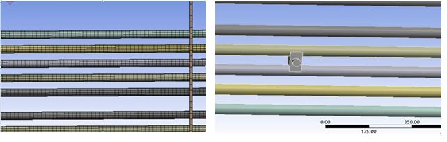
International Journal of Pure and Applied Mathematics Special Issue
1 Introduction
In boilers, economizers are heat exchange equipments that heat wa-
ter to a temperature close to boiling point. Economizers make use
of the enthalpy in the hot streams. Because the streams are usually
still not hot enough to be used in a boiler, economizers recover the
more useful enthalpy and improve the boiler’s efficiency. The effi-
ciency of economizer also depends on the efficiency of the periodic
cleaning of the economizer tubes [1]. The economizer tubes are
provided with a soot removal system called rapping system, which
removes dust that has gathered on the tubes. Dust is dislodged
by inducing vibrations at accelerations, which will effectively de-
tach dust that has collected on economizer tubes. The vibrations
generated at the tubes plays vital role in improving economizer per-
formance. These vibrations are created by gravity operated rapping
system, in which plunger is made to fall on rod. Due to these vi-
brations soot deposited on tubes falls in hoppers. [2]
Thus effective working of rapping system plays important role
in dust removal process. Different accelerations are developed are
at different locations of the system. Accelerations are mainly de-
pends on energy of the rapper at the moment of impact and force is
transferred to the economizer tubes and also geometrical features
of the tubes (shape, length, thickness, diameter). [3]
Various experimental studies were done by researchers to ensure
effective removal of dust from economizer. This experimental ap-
proach has major drawbacks of higher time lines and cost involved
in physical testing. Need is felt to develop a quick and reliable
method to evaluate the vibration performance of economizer tubes.
CAE simulations are often used to for evaluating different designs.
This paper describes simulation procedure for economizer tubes.
2 DETAILS OF ECONOMIZER TUBES
AND RAPPING SYSTEM
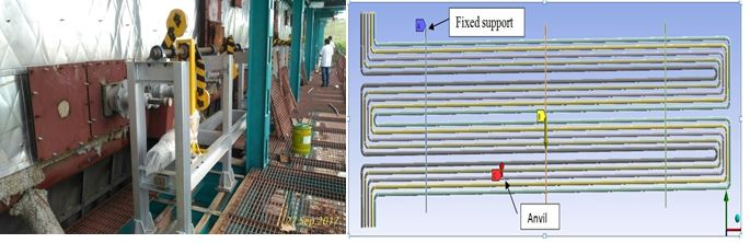
Typical System consists of rows of horizontal economizer tubes
mounted parallaly and hanging from top. Top hangers are mounted
on support channel, which are hanging through roof bolts. Anvil
is mounted on left side from the centre of tubes. On front side of
2International Journal of Pure and Applied Mathematics Special Issue
anvil or tubes rapper rod is placed. Electromagnetically operated
plunger is placed on top of rapper rod which lifts and falls on it
periodically. Due to this impact economizer tube gets vibrated.
These periodic vibrations are responsible for removal of dust from
economizer tubes. Fig.1 shows typical rapping system mechanism.
Fig.1 Details of Rapping system and economiser tubes assembly
3 DETAILS OF FE MODEL
Due to large size of dimensions, use of FEA method for modeling
and analysis of vibrations of economizer tubes is much suitable
option. For finite element analysis assembly of parallel tubes are
considered as shown in fig.2. The software packages are used for
modeling, meshing and analysis of the system. In this economizer
tubes are modeled using shell element. Discretization of the solid
components anvil and connector is done using solid45 element. The
three connectors which hold tubes are considered as fixed from top.
Transient analysis is done by using ANSYS software.
Fig.2 Mesh model and anvil of geometry
3International Journal of Pure and Applied Mathematics Special Issue
4 ANALYSIS METHODS
There were two analysis done for evaluation of economizer and rap-
ping system i.e. modal and transient analysis.
Modal Analysis-
It is done to study of the dynamic character of a system. Modal
analysis provides overview of the limits of the response of system.
It is performed to find out the fundamental frequencies (mode) and
their associated behavior (mode shapes). Refer table 1 for first 6
modes of economizer system. Significance of modal analysis also
helps to set plunger hitting frequency outside the range of natural
frequencies of system. Rapping frequency is 0.3083Hz which is far
away from natural frequency range, so there is no possibility of
resonance to occur.
Table1. Natural frequencies calculated by modal analysis
Transient analysis-
Impact hammer hitting the anvil is transient in nature which
depends on time taken for completing one cycle. Transient analysis
is most appropriate analysis for this kind of operation. Transient
analysis helps to study response of a system for particular time
intervals. Output such as amplitude, acceleration of vibration and
stresses at different location are to be calculated by FEA approach.
4International Journal of Pure and Applied Mathematics Special Issue
As per standards of company 200 mm/s2 is a value where we get
the maximum acceleration. Impact acceleration is calculated by
means of rate of change of velocity. The peak value is calculated
from following equation-
By consideration of momentum
Change in momentum (J) = m (Vf Vi )
Where Vf is final velocity of hammer of 10 kg mass which freely
fallen by gravity from h=60cm
p
Vf = 2gh
J =t∗F
Where t is time that hammer is in contact with anvil and F is
rapping force or impact force.
The calculated rapping force is applied on anvil. Transient
analysis is carried out to find out accelerations, displacements and
stresses at different location. To improve maximum removal of soot
particles on tubes by changing the weights of hammer transient
analysis can be done. The place where we get maximum accelera-
tion and less stress is considered as the effective rapping force.
5 Analysis Results
The transient analysis is carried out in ANSYS. Result data is
mainly governed by model geometry, changing the rapping force
and changing the location of rapping force i.e. characteristic length
from middle support to the left side.
Fig. 3 Location for application of rapping force
Table 2. Transient analysis results for rapping force of 80N
5International Journal of Pure and Applied Mathematics Special Issue
Table 3. Transient analysis results for rapping force of 100N
Above table 2 and table 3 shows displacements, stresses and acceler-
ations at different locations from the centre to left side of connector.
The commercial Ansys software is used for simulations. The differ-
ent rapping forces are calculated and applied on the anvil. Transient
analysis is carried out and final results are shown in above tables.
6 CONCLUSION
Impact location of rapper on economizer tubes plays an important
role in measurement of vibration level. From results, we conclude
that impact force increases the vibration level of tubes. Maximum
acceleration and displacement are occurred at 700mm to left of
middle connector with application of 100N rapping force. So it will
be suitable location for rapping force or impact force.
6International Journal of Pure and Applied Mathematics Special Issue
Acknowledgment
We would like to thank Mr. Sachin Sangamnerkar (Head, Urja
Disha Boilers technologies, Pune) and Mr. Nikhil Patil (Design
Engineer) for giving the opportunity to work on this challenging
project and to present this paper.
References
[1] S. Srikanth, B. Ravikumar, Swapan K. Das, K. Gopalakr-
ishna,K. Nandakumar, P. Vijayan, Analysis of failures in boiler
tubes due to fireside corrosion in a waste heat recovery boiler,
Engineering Failure Analysis, pp. 5966,2003.
[2] A. Nowak, Vibration of collecting electrodes in electrostatic
precipitators - Modelling, measurements and simulation tests,
Journal of Electrostatics , pp. 327-332, 2012.
[3] N. Andrzej, W. Stanisaw, Optimisation and experimental
verification of a dust-removal beater for the electrodes of
electrostatic precipitators, Computers and Structures, pp.
17851792,2004.
[4] I. Adamiec-Wojcik, N. Andrzej, W.Stanisaw, Comparison of
methods for vibration analysis of electrostatic precipitators,
Acta Mech Sin DOI 10.1007.
[5] S.H. Kim, K.W. Lee, Experimental study of electrostatic pre-
cipitator performance and comparison with existing theoretical
prediction models, Journal of Electrostatics, pp. 325, 1999.
[6] A.P. Nowak, Measurement verification of the hybrid finite el-
ement method, ECCM, 2010.
[7] R. Metz, Impact and Drop Testing with ICP Force Sensors,
Sound and Vibration, pp.18-20, february,2007.
7You can also read