Research on efficiency optimization control strategy of WPT system based on optimal load matching
←
→
Page content transcription
If your browser does not render page correctly, please read the page content below

Journal of Physics: Conference Series

PAPER • OPEN ACCESS

Research on efficiency optimization control strategy of WPT system
based on optimal load matching
To cite this article: Qiu Xueying et al 2021 J. Phys.: Conf. Ser. 1871 012032

View the article online for updates and enhancements.

                                This content was downloaded from IP address 46.4.80.155 on 12/09/2021 at 02:02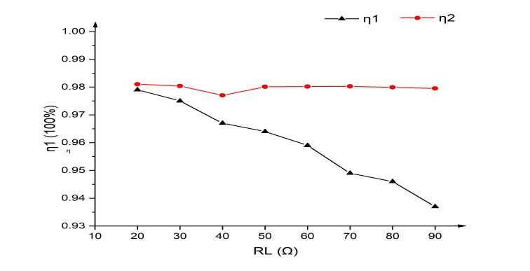
ISAEECE 2021                                                                                                    IOP Publishing
Journal of Physics: Conference Series                         1871 (2021) 012032          doi:10.1088/1742-6596/1871/1/012032

Research on efficiency optimization control strategy of WPT
system based on optimal load matching

                     Qiu Xueying1, Qiao Kangheng1* , Wang Lei1, Liang Yan1, Xie Hailang1
                     1
                      College of Electrical Engineering, Naval University of Engineering, Wuhan
                     430033,China
                     *Corresponding author’s e-mail: xilu@ncepu.edu.cn

                     Abstract. Aiming at the problem that the transmission efficiency of SS-compensated MCR-
                     WPT(Magnetic resonance wireless power transmission) is affected by load changes, this
                     paper uses mutual inductance theory to analyze the equivalent circuit model, obtains the
                     relationship between load and transmission efficiency, and proposes a controllable rectifier
                     bridge for load matching , the front-end cascaded buck converter makes the output voltage
                     regulation control scheme. Finally, modeling and simulation are used to verify the correctness
                     of the load matching theory and control strategy.

1. Introduction
For SS-compensated MCR-WPT, there is an optimal load to maximize the transmission efficiency of
the system [1]. In reality, the size of the system load is often different or variable. Generally, it is
necessary to modulate the load resistance of the receiving end to improve the transmission efficiency,
which is called load impedance matching[2-3].
   Literature [4] adds a matching feed coil after the secondary coil to form a new impedance
transformation structure. The matching feed coil adjusts its own inherent parameters to match different
loads, but the inherent parameter value of the matching feed coil itself requires manual adjustment
and cannot dynamically track changes in load. Literature [5] achieves equivalent load matching by
adjusting the duty cycle D of the downstream DC-DC converter, and adjusts the output voltage by
changing the phase shift angle of the primary side inverter. However, the switching loss caused by the
primary inverter during high-frequency operation cannot be ignored.Literature [6] proposed a new
impedance transformation method based on pulse density full cycle modulation on the basis of a
controllable rectifier bridge structure at the receiving end. However, the matching accuracy of this
method is affected by the on-off ratio.
   Based on the existing research, this paper analyzes the circuit equivalent model by using mutual
inductance theory, obtains the relationship between load and transmission efficiency and the optimal
load value corresponding to the maximum transmission efficiency, in addition,proposes a load
matching structure based on controllable rectifier bridge.Since there are often requirements for output
voltage stabilization in actual situations.In order to reduce the switching loss of the inverter[7], the
voltage stabilizing control scheme of front-end cascaded buck converter is adopted. The correctness of
load matching theory and control strategy is verified by modeling and simulation.

              Content from this work may be used under the terms of the Creative Commons Attribution 3.0 licence. Any further distribution
              of this work must maintain attribution to the author(s) and the title of the work, journal citation and DOI.
Published under licence by IOP Publishing Ltd                          1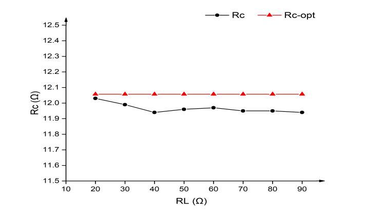
ISAEECE 2021 IOP Publishing
Journal of Physics: Conference Series 1871 (2021) 012032 doi:10.1088/1742-6596/1871/1/012032
2. Structure of rectifier bridge load matching system
Q1 Q3
Rc
Qin Lin
VD1 VD2
R1 C1 i1 C2 R2 i2
Vin Din Cin v1 v2 Co RL
Q5 Q6
Q2 Q4
L1 L2
Figure 1. Structure of rectifier bridge load matching system.
The overall circuit model of the system is shown in figure 1. In figure 1, Vin is a DC voltage source,
Qin is a MOS tube, Din is a diode, Lin, and Cin form a buck converter to adjust the output voltage;The
primary side inverter bridge composed of MOS transistors Q1, Q2, Q3 and Q4 transforms DC into AC,
v1 and i1 are the output port voltage and current,respectively; Li, Ci and Ri (i = 1,2) are the coil
inductance, resonant capacitance and internal resistance of the primary and secondary sides
respectively; the electromagnetic energy is exchanged through the primary and secondary coils, and
the resonant capacitance is used to compensate reactive power; the diodes VD1, VD2 and MOS
transistors Q5 and Q6 form a secondary controllable rectifier bridge, v2 and i2 are input voltage and
current; Rc is input equivalent resistance; Co is output filter capacitor and RL is load resistance.
The four tubes of the primary side inverter conduct complementary conduction, and the output
voltage of the inverter is mainly adjusted by the buck converter connected in the previous stage. Q5
and Q6 on the controllable rectifier are switched on and off at the same time, and the rectifier bridge
output port voltage v2 and current i2 are in phase, as shown in figure 2.
Figure 2. Secondary side control strategy.
The input impedance of the rectifier bridge can be equivalent to a pure resistance Rc, Rc is a
function of the load resistance RL and the pulse width of the controllable rectifier bridge [8].
8
Rc = 2
RL sin 2 (1)
pi 2
3. System equivalent model and efficiency analysis
1 1
Since the system works in resonance( ), the resonance network has sufficient
L1C1 L2C2
filtering effect on high-order harmonics. There is almost only the fundamental wave component in the
harmonic network. The mutual inductance theory is used to establish the system fundamental wave
equivalent circuit model as shown in figure 3.
2ISAEECE 2021 IOP Publishing
Journal of Physics: Conference Series 1871 (2021) 012032 doi:10.1088/1742-6596/1871/1/012032
Figure 3. System fundamental equivalent circuit model.
Among them, the four tubes of the primary inverter conduct complementary conduction, V1 is the
fundamental wave component of the inverter output voltage, V2 is the fundamental wave component
of the rectifier bridge input voltage, and Rc is the equivalent resistance of the rectifier bridge input.
The loop voltage equations at resonance are as shown in equation 2.
R
1 I 1 jwM I 2 V 1
(2)
jwM I 1 (R c +R 2)I 2 =0
By solving equation (2), the loop current expression equation (3) can be obtained.
R2 Rc R2 Rc
I 1 V V1
1
R1 ( R2 Rc ) wM wM
2 2
(3)
I 2 jwM 1
V 1 V1
2
R1 ( R2 R c ) wM jw M
In the above formula, wM ≫ max(R1, R2) , the expressions of transmission power and
transmission efficiency are further derived as equations 4 and 5, respectively.
2
wMU1 U1
2
Pco = R R (4)
R ( R R ) wM 2 c wM c
1 2 c
wM
2
Rc
(5)
( R2 Rc ) R1 ( R2 Rc ) wM
2
Differentiate equation 5 to the equivalent resistance, there is a unique extreme point.
R2
wM
2
Rc-opt = R22 (6)
R1
Substituting equation 6 into equation 5, the maximum efficiency can be obtained.
1
max = (7)
2R1 R2 2R1 R
R 2 wM
2
1+ 2
wM wM
2 2 2
R1
According to equation (1), Rc can be modulated to Rc opt by changing the conduction angle of the
rectifier bridge to maximize transmission efficiency.
4. Simulation analysis
Use MATLAB Simlink to simulate and verify this control strategy. The simulation data is shown in
Table 1.
3ISAEECE 2021 IOP Publishing
Journal of Physics: Conference Series 1871 (2021) 012032 doi:10.1088/1742-6596/1871/1/012032
Table 1.Simulation data.
Lin/uH 20 Cin/nF 600
L1、L2/uH 183 C1、C2/nF 60
R1、R2/Ω 0.1 M12/uH 40
Co/nF 600 f /kHz 48
The output voltage regulation reference value to 40v. According to equation (6),
Rc opt M 12.057Ωat this time.
Figure 4 is a graph of the rectifier bridge input resistance value Rc varying with the load RL. The
load variation range is between 20~90Ω, it can be seen that the matching error is within 0.2Ω, and the
matching accuracy is high.
Figure 4. The rectifier bridge input resistance value Rc varies with the load RL.
Figure 5 is a graph of the system transmission efficiency η varying with the load RL. The load
variation range is between 20 and 90Ω, η1 is the transmission efficiency without load matching, and
η2 is the transmission efficiency after load matching. It can be seen that the larger the load RL, the
more obvious the efficiency optimization effect.
Figure 5. System transmission efficiency η varies with load RL.
Figure 6 shows the output voltage waveform when the load resistance is suddenly changed. When
t=5s, the resistance value is suddenly reduced from 40Ω to 20Ω, and it only takes 0.01s to stabilize at
about 40v, and the output steady-state and dynamic characteristics are excellent.
4ISAEECE 2021 IOP Publishing
Journal of Physics: Conference Series 1871 (2021) 012032 doi:10.1088/1742-6596/1871/1/012032
Figure 6. The output voltage waveform when the load resistance changes suddenly.
5. conclusion
Aiming at the problem that the transmission efficiency of MCR-WPT is affected by load changes, this
paper proposes a control scheme based on a controllable rectifier bridge for load matching and a front-
end cascaded buck converter output voltage regulation control scheme. Finally, modeling and
simulation are used to verify the correctness of the load matching theory and control strategy.
Theoretical analysis and simulation results show that the proposed control scheme can maintain a
stable output even when the load changes.
Acknowledgments
This research was funded by Hubei Provincial Natural Science Foundation Innovation Group
(2018CFA008);General Project of Hubei Provincial Natural Science Foundation
(2019CFB608);National Natural Science Foundation of China Youth Project (52007195).
The authors gratefully acknowledge the above financial support. And the team members of the paper.
References
[1] Pang Haiping, Qiu Yi, Chen Haoran. Maximum efficiency tracking of WPT system based on
optimal load matching[J/OL]. Journal of Power Supply: 1-11[2021-02-28].
[2] Zhang Yanqiang, Jin Nan, Tang Houjun, Xing Kaipeng. Maximum efficiency tracking based on
load impedance matching for wireless power transmission[J]. Power Electronics, 2018,
52(05): 25-27.
[3] Qiu Lisha. Research on impedance matching of magnetic coupling resonance wireless power
transmission[D]. Hunan University, 2016.
[4] Li Fulin, Fan Shaosheng, Li Sentao. Research on impedance matching method under optimal
efficiency of wireless power transmission[J]. Power Electronics Technology, 2015, 49(04):
105-108.
[5] Li Yanling. Integrated control and optimization strategy of wireless power transmission system
for efficiency improvement[D]. Chongqing University, 2017.
[6] Wei Jingyi, Hu Po, Ren Jieshuai, Guan Baoan. Impedance transformation and voltage
stabilization control method in WPT based on PDM[J]. Power Electronics Technology, 2017,
51(02): 110-112.
[7] Diekhans, T., Stewing, F., Engelmann, G., van Hoek, H., & De Doncker, R. W. (2014). A
systematic comparison of hard- and soft-switching topologies for inductive power transfer
systems. 2014 4th International Electric Drives Production Conference (EDPC).
[8] Mai Ruikun, Liu Yeran, Chen Yang. Research on efficiency optimization method of induction
power transmission system based on optimal equivalent load control[J]. Proceedings of the
Chinese Society of Electrical Engineering, 2016, 36(23): 6468-6475+6613.
5You can also read