ESD Protection for HDMI 1.3
←
→
Page content transcription
If your browser does not render page correctly, please read the page content below
ESD Protection for HDMI 1.3
    By Sophie Hou
    Applications Engineer, Semtech Corporation
    (modification of article published on the EETimes Video/Imaging DesignLine in July 2007)

Adding external transient protection for HDMI is difficult due to HDMI’s sensitivity to signal
integrity.

Two essential functions that customers look for in HD video systems are fast data processing and
high-speed interface. Advances in data process technology are shrinking trace geometries and
allowing for more performance and functionality to be included on ever-smaller integrated circuits
(ICs). As for high-speed interface, High-Definition Multimedia Interface (HDMI) is the latest
standard for devices that handle high-bandwidth, real time data, such as HDTV.

However, the higher the data speed and the more advanced the process technology are, the
harder it is to protect the IC adequately from over-voltage stresses caused by ESD (electrostatic
discharge) or CDE (cable discharge events). This is because the designated IC becomes more
sensitive to the transient threats as the technology advances. As a result, HDMI designs often
include additional transient protection to ensure the IC's reliability. Adding external transient
protection for HDMI is difficult, however, due to HDMI's sensitivity to signal integrity. Each
additional device added to the signal line implies extra parasitic elements that can affect signal
transmission.

Introduction to HDMI
HDMI is an uncompressed, all-digital audio/video interface that provides a high-speed link
between audio/video source devices such as DVD players, and sink devices such as HDTVs.
Since its introduction in 2002, the HDMI standard has undergone various revisions to increase its
capabilities. Currently, the most up-to-date HDMI specification is HDMI 1.3, which supersedes its
predecessor HDMI 1.2 by doubling the bandwidth and increasing its speed from 1.65 Gbps per
differential pair to 3.4 Gbps. HDMI 1.3 also includes unique, new features such as Deep Color,
broader color space and the use of the mini connector. These added features enable HDMI 1.3 to
present video images with even more color details and to be used with portable electronics.

HDMI compliance test specification
In order for a product to claim compliance to the HDMI standard, it must receive HDMI
certification. HDMI certification requires that both the sink and the source device comply with their
respective test requirements set forth by the HDMI Compliance Test Specification (CTS).
Although HDMI CTS includes many types of tests, due to the fast signal data speed, it is crucial
to meet the eye pattern requirement for the source devices and the TDR requirement for the sink
devices. In order to meet the eye pattern requirement, the opening of the eye must have a
minimum size as specified by the HDMI eye mask for the source device. To meet the TDR
requirement, the differential impedance of the HDMI signal line pairs for the sink device must be
100 ohm ±15% with the rise time of the test pulse less than or equal to 200ps. Meeting these
requirements is not a trivial task since the opening of the eye and the differential impedance can
be easily affected by introduction of even a small amount of capacitance or inductance.

         Corporate Headquarters: 200 Flynn Road • Camarillo, CA 93012 • Phone (805) 498-2111
                                          www.semtech.com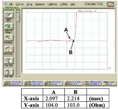
Page 2

ESD Protection for HDMI 1.3 – continued

In addition to signal integrity requirements, the externally accessible HDMI ports are becoming
more susceptible to transients threats. The threats can come from any charged entity; for
example from either a user's direct touch or from hot plugging a charged cable. The internal on-
chip ESD protection does not provide sufficient protection needed to keep the sensitive HDMI
chip from becoming damaged. Thus, most consumer electronics manufacturers require HDMI
ports to meet ESD standard of IEC 61000-4-2. To protect against the over-voltage stress induced
by users and ESD testing, external protection is required. With this added concern, HDMI
designers need to meet ESD immunity requirement of IEC61000-4-2 while maintaining signal
integrity and impedance requirements per the HDMI CTS.

Protecting HDMI from transient threats
In order to meet both the signal integrity and the ESD immunity requirements, the chosen
protection device should have as small of a capacitance value as possible, preferably less than
0.5pF. This is because the lower the protection device's capacitance, the less the device will
affect the differential line impedance when it is added to the HDMI layout. To further facilitate the
high-speed design, the protection device should also offer flow-through, symmetrical layout
capability. Symmetrical and uninterrupted signal layout will help maintain the signal integrity by
streamlining high-speed signal line design and maintain impedance requirements.

In addition to the electrical characteristics requirement, to ensure maximum reliability for the
HDMI IC, the same protection device should provide repeatable ESD immunity to and beyond
level 4, IEC 61000-4-2 ESD to each of the exposed signal pins. In other words, when testing the
I/O or power pin of the HDMI connector, each pin should have a minimum of ±8kV contact ESD
and ±15kV air ESD handling capability when surged directly with ESD and without the ESD gun
touching the connector shield. In conjunction with ESD voltage protection level, another important
parameter to consider is ESD clamping voltage. With the increasing sensitivity to over-voltage
stress in today's ICs, lowering the ESD clamping voltage will reduce the risk of being damaged
further. Thus, it is important that the chosen protection device offers the lowest ESD clamping
voltage possible.

An example of a protection device that meets the aforementioned requirements is Semtech's
RClamp0524P. With a maximum differential capacitance value of 0.3pF, RClamp0524P is a 5V,
10-pin device that can be used directly on two pairs of 100-Ohm differential impedance signal
lines regardless of board characteristics, such as the number of layers or the board thickness.

In other words, designers can design the 100-Ohm differential impedance per their board
parameters, and the RClamp0524P will not cause any change to the already calculated and
controlled impedance. Figure 1 shows an example of high-speed differential trace routing with
the Semtech RClamp0524P.

Figure 1: Flow-through layout of Semtech RClamp0524P for HDMI applications

                                          www.semtech.com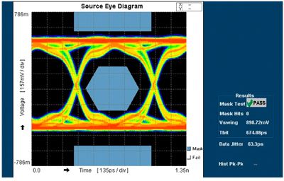
Page 3
ESD Protection for HDMI 1.3 – continued
As can be seen in the layout example, by having 0.5mm pitch to match with the connector pins,
the device package helps maintain the coupling between the differential lines of the same pair.
By having a flow-through design, the protection device also does not appear as an interruption to
the signal routing. This illustrates that the package design is important because a large package
with wide pin pads and pitch can create stubs and signal discontinuities and introduce noise, and
therefore, corrupt the signal integrity. The result is that a small protection device optimized for
high-speed designs is often desired because it can help reduce discontinuities and increase
common noise rejection through tight-pitch coupling.
Test results and recommendations
Low capacitance and a package designed with signal integrity maintenance in mind are desired
for an ideal protection device for HDMI applications.
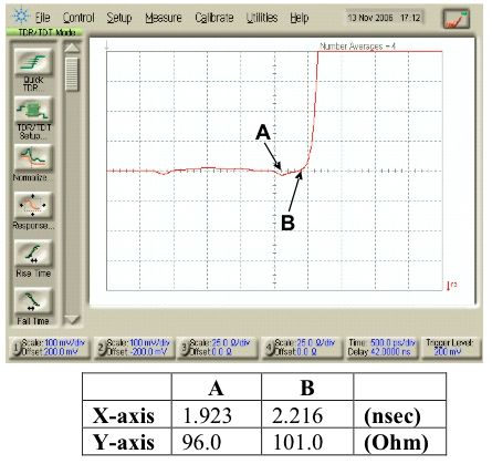
Figure 2 and Figure 3 show respectively the TDR results of Semtech RClamp0524P on 4-layer
and 2-layer HDMI evaluation boards. Both results show that the TDR has met and is well within
the HDMI CTS requirement (100 Ohm ±15% for differential impedance) for the sink devices.
Figure 2: Semtech RClamp0524P 4-Layer HDMI TDR result
www.semtech.com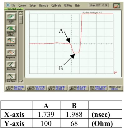
Page 4

ESD Protection for HDMI 1.3 – continued

Figure 3: Semtech RClamp0524P 2-Layer HDMI TDR result

Semtech RClamp0524P comparison with TSSOP package
Figure 4 shows the passing eye pattern result using Semtech RClamp0524P at 1.48Gbps for the
source devices.

In contrast, Figure 5 shows when a TSSOP 38-pin packaged protection device is used on the
same traces with 100 Ohm differential impedance, it can affect the impedance by dropping the
impedance to as low as 68 Ohm.

Figure 4: Semtech RClamp0524P HDMI eye pattern result (1.48Gbps)

                                       www.semtech.com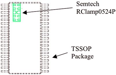
Page 5

ESD Protection for HDMI 1.3 – continued

This result (Figure 5 - below) does not comply with HDMI CTS requirement for the sink devices,
and because the package is large with wide pins, these can introduce signal discontinuity at high
frequency.

Figure 5: TDR measurement of TSSOP 38-Pin on 4-Layer, 100 Ohm differential impedance lines

                                        www.semtech.com
Page 6
ESD Protection for HDMI 1.3 – continued
Figure 6 compares the package size difference between Semtech RClamp0524P and the TSSOP
package.
Significant board compensation would be required in order for this TSSOP package to meet the
HDMI CTS differential impedance requirement. Thus, the use of this package can require several
board design iterations to achieve an acceptable result.
Figure 6: Package size comparison between RClamp0524P and TSSOP package
Conclusion
Designers of HDMI systems are faced with the difficult challenge of providing reliable ESD
protection while meeting signal integrity requirement per HDMI CTS. Proper selection of external
ESD protection devices is imperative. The chosen protection device must exhibit very low
capacitance and high transient threat handling capability while keeping the ESD clamping voltage
at a minimum to maintain the quality and reliability of the protected IC. Package design of the
protection device is also important for signal integrity. These factors will ensure that the HDMI
chip will not experience catastrophic or latent failure during a transient threat. Solutions such as
the Semtech RClamp0524P meet these requirements and provide designers with a reliable and
easy to implement solution.
About the author
Sophie Hou is an Application Engineer with the Protection Products Division of Semtech
Corporation. In this capacity, she focuses on protection solutions for portable and video
electronics, participates in new product definition, and provides global customer support. Sophie's
expertise is in cellular phone and high-speed application layouts as well as tear-down and
analysis of current electronics; she frequently conducts ESD protection seminars, including topics
such as board layout techniques and optimization, proper ESD protection component selection,
and ESD solutions for portable and video electronics, for electronics designers and
manufacturers worldwide. In 2003, she presented a paper at The JEDEX Conference on ESD
devices and ESD testing methods. She received a BSEE degree from the University of California
at Los Angeles and has been an Application Engineer for more than 6 years. She can be reached
at shou@semtech.com.
www.semtech.comYou can also read