Multilayer Ceramic Capacitors in Automotive - Power ...
←
→
Page content transcription
If your browser does not render page correctly, please read the page content below
36 AUTOMOTIVE POWER www.knowlescapacitors.com
Multilayer Ceramic
Capacitors in Automotive
Modern EV’s, HEV’s and PHEV’s are sparking a revolution in the capacitor technology used in the control
electronics. Higher temperatures inside the control circuits mean that conventional plastic film capacitors are
no longer suitable for all applications and ceramic MLCC’s are now being increasingly used, with the added
benefits that MLCC’s are generally surface mount direct to boards, yielding greater efficiency of assembly
and allowing shorter circuit tracks with lower inductance. In many cases this last point allows lower
capacitance values to be used, meaning that smaller components or less components can be used.
Steve Hopwood, Senior Applications Engineer, Knowles Capacitors R & D, Norwich, UK
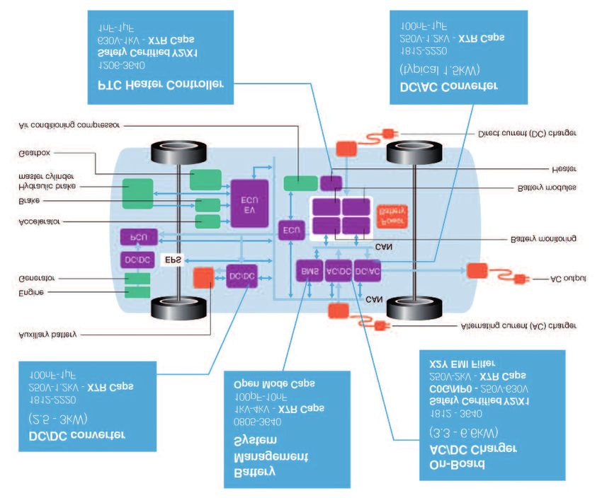
According to Figure 1, MLCCs are being rigorous tests to determine the basic reliability suffering from a mechanical crack which may
used extensively in modern cars. In in application. Generally, the most severe tests result in a short circuit at a later date (see
considering the basic requirements for MLC for MLCCs relate to the mechanical stresses Figure 2).
chips, first we must consider the necessity for induced by the board bend and thermal
all components to meet the demanding cycling requirements, designed to ensure a Avoiding cracks due to mechanical
requirements of AEC-Q200, the “Stress Test component is capable of withstanding poor stress
Qualification for Passive Components” laid processing and handling, as well as the Knowles Syfer brand were the first MLCC
down by Automotive Electronics Council mechanical stresses experienced in manufacturer to develop a flexible
(AEC) Component Technical Committee. application. Poor mechanical design and termination system for their surface mount
These subject components to a set of material selection can result in a component capacitors - FlexiCap™. This technology
Figure 1: Some examples of locations where MLCCs are now being used in (electric) automotive applications
Issue 2 2017 Power Electronics Europe www.power-mag.com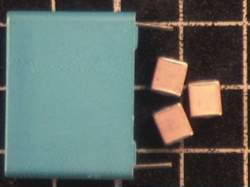
www.knowlescapacitors.com AUTOMOTIVE POWER 37
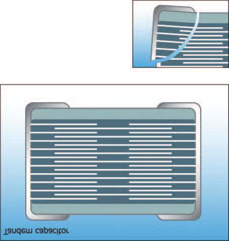
Figure 2: a sequential electrode design, placing two
Mechanical capacitors in series within a single MLCC.
crack Each capacitor is designed to withstand the
mechanism full rated voltage of the component, so in the
case of a failure in one, the capacitor the
other end can withstand the full rating and
the component continues to work, albeit at a
reduced capacitance value. These recent
developments have made the reliability of
surface mount MLCCs exemplary, which in
turn has seen an increase in their use
throughout a car’s electronics.
makes it possible for large case size MLCC’s, design special internal electrode One noticeable trend of late has been the
up to 3640, to be approved to the AEC- configurations to reduce the likelihood of increasing ambient temperature of the
Q200 requirements by isolating the ceramic catastrophic electrical failure in the case a electronic systems on board. Airflow, required
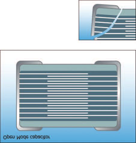
from the mechanical stresses. This crack does occur. Open-mode MLCC’s for cooling, is more closely controlled as
termination is essential to ensure type II (Figure 3) have the internal electrode aerodynamic drag is more of a concern;
(X7R, X5R & X8R) dielectrics meet the patterns pulled back from the opposing end miniaturization drives enclosures even
requirements of the AEC-Q200 specification, of the chip, meaning if a crack is induced, it is smaller; the complexity of on-board systems
although it is also available on selected type I much less likely to propagate through an area has reached levels that could not have been
(C0G / NP0) dielectric ranges. of active overlap and cause an electrical short imagined and, with the advent of battery and
Alongside the termination, it is possible to circuit. Tandem-mode designs (Figure 4) use power train control systems, components are
being asked to handle higher power ratings.
Figure 3: Open-mode MLCCs with X8R classification (rated -55ºC
MLCC’s have the to +150ºC) were developed many years ago
internal electrode specifically for automotive applications, but
patterns pulled back have always had poor volumetric efficiency
from the opposing compared to other dielectrics. Recent new
end of the chip dielectric systems are now addressing this and
recent developments have seen significant
improvements in the available ranges. This
factor is actually a side effect of the new
dielectrics being developed for environmental
reasons, which have also seen the first 100 %
lead free X8R capacitors reach the market.
Coming soon
Looking to the future, temperatures will
continue to rise as passive components are
moved closer to the power electronics,
reducing the circuit tracks and therefore the
effective inductance but also allowing lower
capacitance values to be specified. Here, the
automotive industry can look to
developments in the oil exploration down-
Figure 4: Tandem-
hole industry, which has seen 200ºC MLCCs
mode designs use a
arrive on the market. For the first time, these
sequential electrode
are available with low-cost plated, nickel
design, placing 2
barrier, termination systems allowing the full
capacitors in series
requirements of aged solderability and
within a single MLCC
dissolution of termination specifications to be
met. These systems meet the full
requirements of the AEC-Q200 specification
on C0G type I dielectrics. Future
developments will see available temperature
ranges increase further, with 250ºC rated
parts already on the horizon.
Electric vehicles require higher voltages
Early on we stated that there was a revolution
in the capacitor technology used in the
control electronics being driven by modern
EVs, HEVs and PHEVs. Of course, MLCCs
have been used in automotive applications
for years, but the big change that is being
seen is the voltage rating and size of
www.power-mag.com Issue 2 2017 Power Electronics Europe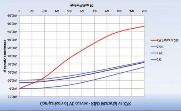
38 AUTOMOTIVE POWER www.knowlescapacitors.com
Figure 5: Examples automotive applications as plastic film offers
of 400 V DC 1 µF much higher capacitance ranges, but where
Polypropylen film possible an MLCC can offer a much smaller
and 630 V 1 µF component size and weight for the
MLCC capacitors equivalent plastic film (Figure 5).
(right) Developments continue to drive the size
of MLCC’s ever smaller, and new dielectric
systems are now obtaining impressive
volumetric efficiency. The 0.22” x 0.20” x
0.18” 630 V DC rated 1 µF X7R MLCC is a
typical example that is now in use in EV
battery management systems. This
capacitance / voltage combination is only
possible due to Knowles patented
StackiCapTM technology which allows
increased component thickness without the
electrostrictive failure mode that plagues
components now being used. Not so long power dissipation). With reference to Figure thicker MLCC’s.
ago, there was a rule of thumb that you 1, it can be seen that typical MLCC voltage in In PHEV’s and PEV’s, it is also important
didn’t place an MLCC bigger than 1210 EV is 250 V DC to 2 kV DC, but 4 kV DC and that the appropriate safety rated class X & Y
(0.12” x 0.10”) directly onto a board due to higher is required in some cases, particularly capacitors are used on the circuits directly
the risks to reliability. The developments to meet impulse or surge requirements. connected to the mains and elsewhere were
mentioned above have smashed this ceiling Typical capacitance in this application is 100 an electric shock situation could possibly
and it is now not unusual to see capacitor as nF to 4.7 µF. The reason for these high occur. MLCCs are capable of safety approvals
large as 0.5” square and up to 0.3” thick values is the manner in which MLCCs are up to class Y2 and all Knowles safety ranges
placed directly onto substrates. now being used to replace film capacitors in are also AEC-Q200 certified.
The size increase is being driven by the filtering circuits with high DC bias voltage and Of course it is important that the capacitor
need for higher voltages, higher capacitance high ripple current requirements. Ceramic will characteristics and performance under real
values and higher AC ripple currents (i.e. never eradicate film capacitors from life operating conditions are known and to
this extent Knowles are investing heavily in
research and development and working
closely with a number of automotive
electronics suppliers to assist with
applications advice.
Finally, we can look forward to some new
dielectric developments that are specifically
aimed at the future requirements of
automotive power electronics. An example of
one such development is shown in Figure 6 -
this particular dielectric development is
currently being developed under the
European Union’s FP7 Clean Sky Joint
Technology Initiative with project partners
NPL and Euro support. These materials are at
the R&D stage and promise to offer more
stability under voltage stress, less dielectric
losses and significantly reduced self-heating
of the component under high RMS ripple
current. These new dielectrics are already
undergoing BETA trials in automotive
applications in case sizes as large as 0.4” x
0.4” x 0.2”, typical voltage and capacitance
ratings of 600 V at 1.7µF.
Conclusion
MLCC’s are experiencing a boom in
automotive applications as their use expands
into EV related power electronic applications.
Larger case sizes and higher voltages are
promoting replacement of film capacitors
with the advantages of lower inductance,
smaller case size and higher temperature
ratings. New dielectric developments over the
next 12 months will push MLCC’s into further
Figure 6: Dielectric development being developed under the European Union’s FP7 Clean Sky Joint applications with their lower loss and more
Technology Initiative, comparison of VC curves (top) and temperature rise versus current (above) stable characteristics.
Issue 2 2017 Power Electronics Europe www.power-mag.com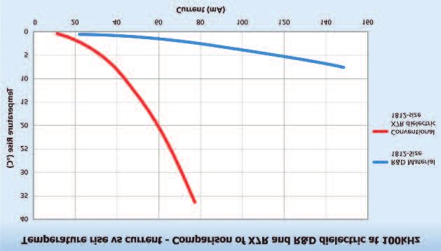
You can also read