Arc Terminator Active Arc-Resistant Switchgear
←
→
Page content transcription
If your browser does not render page correctly, please read the page content below
Arc Terminator™
Active Arc-Resistant Switchgear
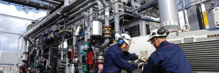
Increasing safety and productivity by extinguishing internal arcing
faults within the switchgear.
The Square D® Arc Terminator™ from Schneider Electric offers unsurpassed arc flash protection for personnel and
equipment. Developed through careful design, analysis and testing to go beyond the IEEE C37.20.7 test guidelines,
the Arc Terminator system helps to deliver an additional degree of protection from arcing faults in medium-voltage
switchgear. You will no longer have to compromise desired protective relay settings and coordination to achieve
improved arc flash protection.
Now there is Arc Flash and Arc-Resistant protection in one solution: Active Arc-Resistant Switchgear.
Key Benefits
• Achieve all arc resistant accessibility types1
– Type 2A, 2B, 2C per IEEE C37.20.7, UL witnessed
• Reduce incident energy and arc flash hazard
– Level 0 PPE, even with doors open2
• Reduce downtime caused from arcing event
• Minimize equipment damage
• Eliminate special requirements for buildings
– Venting and exhaust plenums are not required
• Reduce lineup footprint and weight as compared
to “traditional” arc resistant switchgear
1
When configured with no unprotected zones within MasterClad™ switchgear.
2
Based upon IEEE Std. 1584-2002 methodology with functional Arc Terminator system.
System Operation
                                                    Arc Terminator™ Active
In the event of a confirmed internal arcing fault, the high-speed, electromechanical switch provides a low impedance
parallel path to effectively transfer the fault current from the arc to the three-phase, main bus assembly of the switchgear.

                                                    Arc-resistant Switchgear
The main bus carries the fault current while it is being sensed and cleared by the normal complement of current
transformers (CTs), protective relaying, and upstream over-current protective device.

The high-speed switch is closed by a control unit via an output signal produced by simultaneous input from
two different sensors:
                                                   Increase safety and productivity: Extinguish
                                                   internal
  1) A current sensor that detects both a discontinuity         arcing
                                                         occurring          faults
                                                                   in the current    within
                                                                                  waveform andthe    switchgear.
                                                                                               the exceeding
     of a threshold current level.
  2) An optical sensor that visually detects the arc.Benefits
                                                    U controller
These signals are sent to a “digital AND gate” in the Complieswhich
                                                                  with processes
                                                                       IEEE C37.20.7,    UL witnessed
                                                                                  the signals and sends an output to close
the switch. The combination of these two signals prevents   nuisance
                                                    U Reduces         operations.
                                                                 incident energy and arc flash hazard
Arc Terminator™ protection is limited to its zone of Uprotection,
                                                        Reduceswhich
                                                                  operating
                                                                        can bedowntime
                                                                                configured to protect the entire switchgear
lineup. The Arc Terminator operation does not impact U Minimizes equipmentrelaying
                                                          the normal protective  damage functions, nor does it change
any protective relaying system settings. The fault clearing duty remains under the domain of the main circuit breaker
                                                     U Eliminates special requirements for buildings and plenums
or upstream over-current protective device. Additionally, the Arc Terminator system can be used in most applications,
regardless of the type of load being connected to the switchgear.

Key Features                                                 High- speed
                                                             switch (front)
• UL witnessed and meets all the requirements
   of C37.20.7 Test Guidelines for Arc-Resistant
   equipment                                                                                                   Light detector

• Active system provides an additional degree of
   protection for both personnel and equipment
• Reliability; perform system self checks during
   operation                                                                                                   System display

• Display captures and logs location, time,
   and date of arcing event. Quick diagnosis
   and recovery
• 50 kA fault capability throughout the                                                                       Junction box
   protected areas

Typical Applications
• 5 and 15 kV medium voltage equipment
• Applications requiring arc flash hazard                      Components of Arc Terminator System
   reduction and or arc-resistant equipment
   (examples include oil and gas facilities,
   industrial facilities and hospitals)
Arc Terminator™ Active Arc-Resistant Switchgear
Side View Diagram of the High-Speed Switch Mounted above a 1200/2000A
Circuit Breaker in Masterclad® Switchgear (example arrangement)

Radial Distribution Scheme (Main and Feeder Breakers) with AT System (example arrangement)

System Ratings and Specifications

Type                                                                   Ratings

                                Nominal Fault Currents (I)             25 kA rms         40 kA rms     50 kA rms

                                Continuous Current Rating              Not applicable

Currents                        Making Current                         2.6 x l kA peak

                                Short Time Current                     48 kA for 1 second

                                Interrupting Current                   Not applicable

                                Maximum Operating Voltage              15 kV rms

Voltages                        60 Hz. One Minute Withstand            36 kV rms

                                BIL                                    95 kV

                                Total Operating Time                   5.5 ms            4.5 ms        4.0 ms

                                Mechanism Reset                        Manual only

Mechanical                      Closing Mechanism                      Spring operated with electrodynamic assist

                                Mechanical Operating Life              100 operations

                                Electrical Operating Life              4                 2             1

                                Normal Operating Ambient Temperature   -30°C to + 40°C

Environmental                   Seismic                                2003 IBC maximum California requirements

                                Humidity                               Up to 95% RH

                                                                       Instantaneous analog detection from CT on main
Fault Detection                 —
                                                                       bus entrance

                                                                       Optical detectors installed on each individual
Arc Detection                   —
                                                                       compartment

                                                                       Provided by the output of AND gate for simultaneous
Closing Signal                  —
                                                                       fault current and optical signals

Initial Power Up Time           —                                      Max 1 minute with LED indicator

Power Supply Requirements       —                                      104–254 Vac or 70–250 Vdc11

Auxiliary Contacts              —                                      2a and 2b type contacts (Form C)

48 Vdc realized via converter
1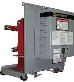
Incident Energy Reduction*

             4.76-15.0 kV Class with Arc Terminator System1                                                          4.76-15.0 kV Class without Arc Terminator System2

         Arcing Fault                  Working                   Incident                                          Arcing Fault     Working       Incident
           Current                    Distance                    Energy                  PPE Level                  Current       Distance        Energy      PPE Level
            (in kA)                  (in inches)               (in cal/cm²)                                           (in kA)     (in inches)   (in cal/cm²)

                25                        18                        0.46                        0                        25           18           4.19           2

                40                        18                        0.62                        0                        40           18           6.91           2

                50                        18                        0.70                        0                        50           18           8.76           3

    *
        Data based upon IEEE Std. 1584-2002 methodology.
    1
        Data based upon functional Arc Terminator System.
    2
        Data assumes fault clearing time of 50ms (3 cycles). 5 cycle breakers will have higher incident energy levels.

                    System Compliance Standards*

        Codes and Standards                                  Descriptions

                                                            Industrial Control Equipment, Sixteenth Edition, February 1993, and any identified
        UL508
                                                            subsidiary standards

        CSA-C22.2, No. 14-M91                               Industrial Control Equipment, September 1991

        IEC61000-4                                          Electromagnetic Compatibility for Industrial-Process Measurement and Control Equipment

                 Section 2                                  Electrostatic Discharge Requirements, First Edition, 1995

                 Section 3                                  Radiated Electromagnetic Field Requirements, First Edition, 1995

                 Section 4                                  Electrical Fast Transient/Burst Requirements, First Edition, 1995

                 Section 5                                  Surge Immunity Requirements, First Edition, 1995

        C37.90-89 IEEE                                      Standard for Relays and Relay Systems Associated with Electrical Power Apparatus

        C37.90.1-89 IEEE                                    Standard Surge Withstand Capability (SWC) Tests for Protective Relays and Relay Systems

                                                            Standard for Withstand Capability of Relay Systems to Radiated Electromagnetic Interference
        C37.90.2-95 IEEE
                                                            from Transceivers

        IEC60068.2                                          Basic Environmental Testing Procedures

                 Section 6                                  Vibration (sinusoidal), Sixth Edition, 1995

                 Section 27                                 Shock, Third Edition, 1987

                 Section 29                                 Basic Environmental Testing Procedures Part 2: Tests

                 Section 31                                 Drop and Topple, Second Edition, 1975
*
    System conforms to the referenced Industry Standards.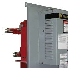
Leader in Arc-Resistant
             Switchgear Solutions
             Passive and active solutions available to fit
             your facilities’ needs.

Schneider Electric also offers a complete passive arc-resistant switchgear solution for those
who prefer this method. For more information on this method, please refer to document
number 6055HO0901.

When properly configured, both active and passive systems fully comply with IEEE C37.20.7
with ratings up to 50 KA but use two totally different approaches.

               For more information, contact Schneider Electric
               by phone at 1-888-778-2733, by e-mail at
               help@SquareDinfo.com or visit www.schneider-electric.us
                                                                                                                     ©2010 Schneider Electric. All rights reserved.

Schneider Electric USA, Inc.
                      1415 S. Roselle Road
                      Palatine, IL 60067
                      Tel: 847-397-2600
                      Fax: 847-925-7500
                                                                                 This document has been
                      www.Schneider-Electric.us                                  printed on recycled paper

6000HO0902                                                                                                   01-10
You can also read