Introduction of Secondary Frequency Control in Indian Power System - 16th Mar 2018 - ERPC
←
→
Page content transcription
If your browser does not render page correctly, please read the page content below
Introduction of Secondary Frequency Control
           in Indian Power System

              16th Mar 2018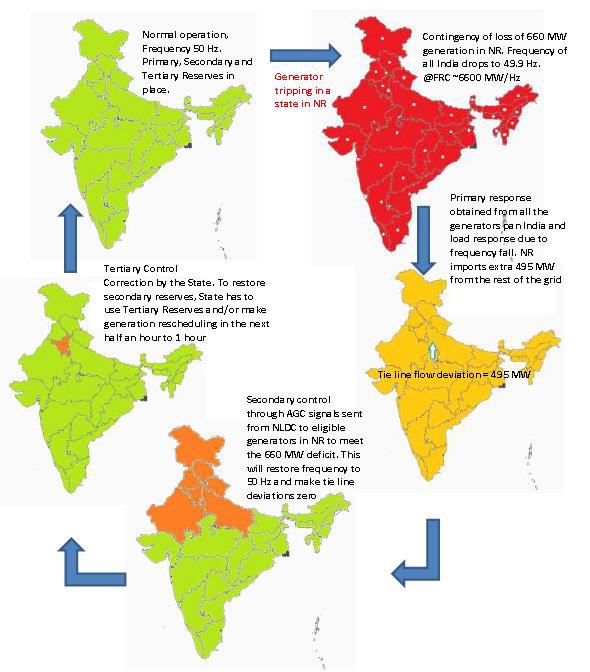
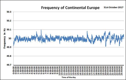
F e uen y P ofile o e the yea s…

                          Slow Tertiary
                          implemented
                          from April, 2016
India…Cat hing up ith Best in the Wo ld

S.No Description                                       Values for
                                                    CE          India
 1   Standard Deviation (Hz)                      0.019         0.042
 2   Frequency Variation Index (FVI) in Hz       0.0036         0.020
 3   Instantaneous maximum frequency (Hz)        50.060        50.154
 4   Instantaneous minimum frequency (Hz)        49.916        49.885
 5   15-minute maximum average frequency (Hz)    50.033        50.065
 6   15-minute minimum average frequency (Hz)    49.965        49.952
 7   % of time frequency within 49.90-50.05 Hz    99.61         81.08
 8   % of time frequency below 49.90 Hz           0.00           0.06
 9   % of time frequency above 50.05 Hz           0.39          18.86
Load Following and Regulation

                Regulation

           Load Following
Frequency Control Continuum in India
Frequency Control Response
System
Frequency Restore Normal
50 Hz
Deviation from 50 Hz 5-30s
Primary Free
Activate Control Reserves
30s – 5 min+
Take Secondary Free
Activate Over Control Reserves
> 5 min +
• Primary (droop) control Take Tertiary
Obligatory, Automatic response Over Control
• Secondary (AGC) control
Spinning reserve, NLDC/RLDC/SLDC controlled, Automatic Generation Control (AGC)
• Tertiary control
Tertiary Reserve and response from State, Manual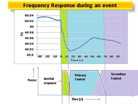
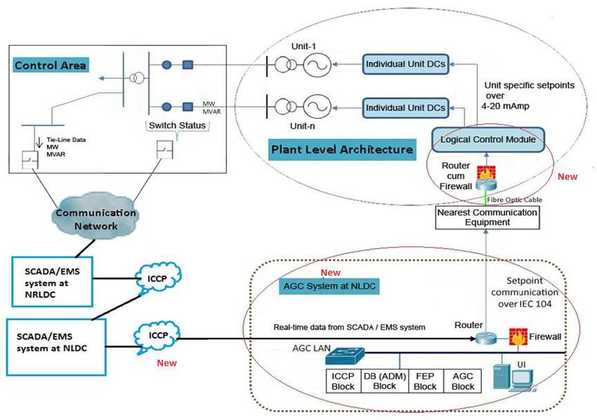
Immediate Frequency Response after an Event
Rate of change
of Frequency
C. Quasi Steady State Frequency
B. Nadir Frequency
Importance
of Inertia
Load
Frequency
Nadir
Quasi Steady
State
Frequency
All in a day’s play…Repeated again and again
Timeline of Activities

Roadmap to
operationalise                                No ’1           Under
Reserves in                   Jan’1           Hon’ le CERC    continuous
the country      Ma ’1        LOA to          visit to NTPC   operation from
O t’1            FOLD meet    M/s Siemens     Dadri           4th Jan’1

          Jan’1           POSOCO       Mock Test        CERC Order
          Brainstorming   visit to     29th Jun’1       6th De ’1
          session         NTPC Dadri
                          May’1
Region considered as an Area for secondary control
ACE = (Ia - Is) + 10 * Bf * (Fa - 50)
NORTHERN
REGION
NORTH-
EASTERN
REGION
WESTERN
Eastern Ia = Actual net interchange, negative for NR
REGION
REGION meaning import by NR
EASTERN
Is= Scheduled net interchange, negative for NR
REGION
meaning import by NR
Bf = Frequency Bias Coefficient in MW/0.1 Hz,
positive value
SOUTHERN Fa = Actual System Frequency
REGION
ACE positive means NR is surplus and NR
internal generation has to back down
ACE negative means NR is deficit and NR
internal generation has to increase
• Tie line bias mode and Frequency bias only mode both possible
• Interchange scaled using a factor of 15, changeable
10Data Flow in AGC Project
AGC console at
NTPC
AGC Local/Remote
AGC On/OFF Unit Load Set Point Factor
AGC Set point Actual Generation
Scaled ACE Circuit Breaker Status
Back-up
NLDC AGC System at AGC RTU
ICCP IEC 104 Protocol
SCADA NLDC at NTPC
NR-IR Schedule AGC Set point
NR-IR Actual
Frequency AGC Local/Remote
Unit Load Set Point DeltaP
Actual Generation
Circuit Breaker Status
NTPC DCSArchitecture of the Project
Existing New
NewDisplay at NLDC
AGC Compensation Mechanism

        Up Regulation

                                               Down Regulation
 Payment from Pool +                         Payment to Pool +
Incentive to Generator                     Incentive to Generator
                         5-Minute Accounting
Future Ready AGC for 175 GW of RE by 2022 • Forecasting of Load & RE • Use of Pumped Storage Plants • Automatic controls
Detailed implementation plan to operationalize the
           spinning reserves in the country
• Detailed plan submitted to CERC on 14th July 2017
• Secondary Control as an Ancillary Service.
• https://posoco.in/download/detailed-modus-operandi-on-
  operationalization-of-spinning-reserves/?wpdmdl=13461
• Phase-I
   – All the ISGS generators whose tariff is regulated / adopted
     by CERC
• Phase-II
   – To improve the availability of Reserves
   – All Regional Entity generating stations scheduled by RLDCs
   – Over and above the Phase-I power stations
Essential requirements for Secondary Control
• Shall bear the cost of secondary control hardware at
the plant end
– Including the cost of the fibre optic cable
• Shall share DC and Schedule like ISGS generators on
day ahead basis
– Subsequent revisions with RLDCs
• The generating units shall have working control
systems for turbine, boiler and governor
– Governor response plots/graphs of past incidents have to
be submitted to RLDC
• Existing wide band communication node
– Within a radius below 30-40 km from the plant
– Detailed survey is given in Annexe-VI of the reportCoordinated action items • Ensuring accurate load forecasting and Renewable Energy (RE) forecasting. • Proper scheduling by each state including indication of reserves • Evaluate Area Control Error (ACE) of each control area • The SLDCs must also monitor the primary response from the generating units within the state • Periodic monitoring of the data quality needs to be done at the RPC forums • Fibre optic communication from Regional Entity power plant to nearest CTU node and there on to RLDCs/NLDC • Ensure adequate reserves for secondary control • Renewable Energy (RE) resources under AGC
Pathway to Pan-India AGC Rollout

1                                     100+
Generation Plant                      Generation Plants

    1 GW                                        65 GW+
    Generation plant under pilot                By 2022

₹ 1 Crore                              ₹ 150 Crore+
Project Cost                           Pan-India roll out

       2000                                  25000+
       Highly Skilled Manhours               Highly Skilled Manhours

50 km                                  1000s km
Existing Communication path            Existing Communication path

           6 km                                     140 km+
           Optical Fibre (GI Piped)          Optical Fibre (GI Piped)
Image Credit: NASA
20You can also read