Introduction to engineering geology and geomorphology
←
→
Page content transcription
If your browser does not render page correctly, please read the page content below
Downloaded from http://egsp.lyellcollection.org/ by guest on April 26, 2021

Chapter 1 Introduction to engineering geology and geomorphology
of glaciated and periglaciated terrains
        C. J. Martin1*, A. L. Morley2 & J. S. Griffiths3
        1
         BP Exploration Operating Company Ltd, Chertsey Road, Sunbury-on-Thames TW16 7LN, UK
        2
         Ove Arup & Partners Ltd, 13 Fitzroy Street, London W1T 4BQ, UK
        3
         School of Geography, Earth and Environmental Sciences, University of Plymouth, Plymouth
        PL4 8AA, UK
        *Correspondence: christopher.martin@uk.bp.com

        Abstract: This chapter provides an introduction to the Engineering Group of the Geological Society of London (EGGS)
        Working Party book on the engineering geology and geomorphology of glaciated and periglaciated terrains. A summary of
        changes in the extent of glacial and periglacial conditions throughout the Quaternary to the present day is provided initially.
        The engineering difficulties associated with working in glaciated and periglaciated terrains are demonstrated through the
        inclusion of seven important case histories. The chapter then discusses the background to the Working Party, the scope
        and structure of the book, including abstracts of each chapter, before finally guiding the reader on how the book may be
        used at a site where glacial or periglacial conditions had formerly prevailed. In particular, the importance of updating
        the ground model at each stage of the project as an approach to risk management is emphasized.

        Gold Open Access: This article is published under the terms of the CC-BY 3.0 license.

   When the work of the geologist is finished and his final compre-        their engineering geological characteristics and their geotech-
   hensive report written, the largest and most important chapter will   nical properties. Appreciating the sedimentological inheri-
   be upon the latest and shortest of the geologic periods               tance of glacial, periglacial and permafrost processes is
                                                  Gilbert 1890, p. 1.    therefore fundamental to any understanding of the engineer-
                                                                         ing geology and geotechnical behaviour of both soils and
                                                                         weathered bedrock in Great Britain and similar environments
                    1.1 Introduction                                     overseas. It was for these reasons that the Engineering Group
                                                                         of the Geological Society of London (EGGS) established a
At present, glaciers only cover about 10% of the Earth’s sur-            Working Party to produce this state-of-the-art book on The
face (Owen & Derbyshire 2005; Benn & Evans 2010). That is                Engineering Geology and Geomorphology of Glaciated
a total of over 15 million km2, with 99% found in the ice                and Periglaciated Terrains.
sheets of Antarctica and Greenland. However, over the past                  It must be acknowledged that the extent of contemporary
2.6 Ma of the Quaternary Period there have been multiple                 glacial and permafrost limits (Figs 1.1 and 1.2) has changed
phases of spatially more extensive ice and permafrost around             significantly since the 2005 summary paper by Owen &
the globe (see Chapter 2). Even as recently as 18–24 ka at the           Derbyshire (2005). The changing climate has reduced the
Last Glacial Maximum this coverage was as high as 30% and,               permanent ice coverage that has been replaced with newly
during some earlier glacial advances, the ice coverage was               exposed areas of permafrost/periglacial activity. There are
even higher. The former and current global glacial extents               also many reports of loss of permafrost affecting native com-
are shown in Figure 1.1. Currently active periglacial condi-             munities in Alaska and northern Canada (Sven Lukas, pers.
tions occur in 25% of the world’s land area (French 2007)                comm. 2016). It is anticipated that these changes will con-
with permafrost (perennially frozen ground) underlying                   tinue in response to global climate change (ACIA 2005;
20%, mainly in the Northern Hemisphere (Walker 2005).                    IPCC 2014), which means that the extent of formerly glaci-
The former and current global extents of periglacial influence            ated and periglaciated terrains will continue to increase. The
are shown in Figure 1.2. In most of NW Europe, Asia and                  driving mechanisms for present-day climate change are con-
North America it is the legacy of these ice advances and                 sidered to be outside the scope of this book; here, the focus is
retreats, along with the migration of periglacial and perma-             on the engineering geology and geomorphology of glaciated
frost conditions, that dominate the distribution of soils,               and periglaciated terrain resulting from Quaternary stadials.

Engineering Group Working Party (main contact for this chapter: C. J. Martin, BP Exploration Operating Company Ltd, Chertsey Road,
Sunbury-on-Thames TW16 7LN, UK, christopher.martin@uk.bp.com)
From: GRIFFITHS, J. S. & MARTIN, C. J. (eds) 2017. Engineering Geology and Geomorphology of Glaciated and Periglaciated Terrains –
Engineering Group Working Party Report. Geological Society, London, Engineering Geology Special Publications, 28, 1–30
https://doi.org/10.1144/EGSP28.1
© 2017 The Author(s). Published by The Geological Society of London.
Publishing disclaimer: www.geolsoc.org.uk/pub_ethics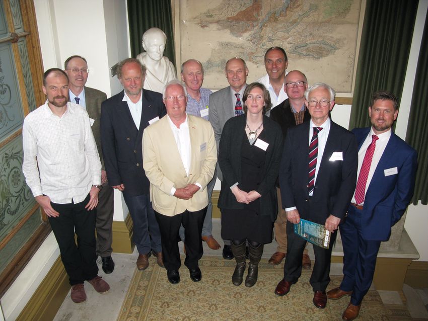
Downloaded from http://egsp.lyellcollection.org/ by guest on April 26, 2021

2                                                      INTRODUCTION

Fig. 1.1. Map showing approximate limits of Northern Hemisphere ice sheets at the present day and during the Last Glacial Maximum
(LGM). Ice caps and smaller glaciers are omitted. Based on Hubbard et al. (2006), Andrews & Dyke (2013), Ehlers et al. (2013) and
Hughes et al. (2016).

   As a general rule, engineering geologists and geotechnical      and programme, and which can only be identified from a
engineers are typically only concerned with the upper few          detailed examination of soil samples.
metres, or tens of metres, of ground that underlie a site of          To demonstrate how it is critical to understand the nature
interest. This is in contrast to hydrogeologists, mining geolo-    and formation of glacial and periglacial terrain to overcome
gists and petroleum geologists whose zone of interest is the       engineering difficulties, a selection of seven case histories
upper hundreds to thousands of metres of ground that host          is presented in Section 1.2. These case histories are presented
their resources. While it is important for engineering geolo-      in order of age, starting in 1908, and demonstrate some of
gists to understand the formative processes and resulting mate-    the typical engineering problems that have been encountered
rials and structures of the ‘deep geology’, it is generally the    over the past 100+ years working in these materials. How-
geological events of the Quaternary that have an overwhelm-        ever, this is only a very small sample of the many examples
ing influence on the characteristics of the near-surface rocks      that can be found in the scientific literature (e.g. Kiersch
and soils (Fookes 1990, 1997a, b), as illustrated in Figure 1.3.   1991). While Section 1.2 sets the historical context for the
   The extent of the dominant glacial and periglacial influ-        work, Section 1.3 presents the background, aims and specific
ence in the top few tens of metres means that many engineer-       objectives of the Working Party. In Section 1.4 the scope of
ing structures are located within these variable and complex       this book is summarized and Section 1.5 provides the struc-
soils and rocks. A glossary of ground conditions that could        ture of this book, including the abstracts of Chapters 2–9.
be encountered (Chapter 3) helps to confirm the variability         Finally, Section 1.6 guides the reader on how the book may
and complexity that might be seen during an engineering pro-       be used at a site where glacial or periglacial conditions
ject. This ranges from regional-scale structures found during      have prevailed. In particular, the importance of updating
the desk study and walkover to a micro-scale soil fabric that      the ground model at each stage of the project as an approach
can have a profound influence on construction safety, cost          to risk management is described.
Downloaded from http://egsp.lyellcollection.org/ by guest on April 26, 2021

                                                       INTRODUCTION                                                             3

                                Fig. 1.2. Former and current Northern Hemisphere permafrost extents.

  1.2 A history of engineering difficulties                            The case histories presented below are in chronological
                                                                   order and reflect the state of knowledge and understanding
        in formerly glaciated and                                  by the geologists and engineers at the time of the projects.
           periglaciated terrain                                   While the tunnel construction through a glacial over-
                                                                   deepened valley presented in Case History 1.1 at Lötschberg
The engineering geological importance of former periglacial        occurred over 100 years ago, it is a classic example of the
and glacial conditions is illustrated by the following seven       ability of a glacier to over-deepen a valley to such depths
case histories of engineering failures that resulted from a        not thought conceivable from the scientific knowledge at
lack of appreciation at that time of the influence of periglacial   that time; it was a case of an ‘unknown unknown’. Today’s
and glacial processes on materials and landforms. These case       updated landsystems approach to the understanding of
histories have been selected to demonstrate the effect of such     these terrains (Chapters 4 and 5) now contributes to more
features on a wide range of national and global engineering        robust ground models and therefore more carefully targeted
projects including tunnels, dams, transport infrastructure,        ground investigations based on the lessons learnt from this
slope instability, building foundations and offshore structure     case history. An example of these advances is presented
foundations. Further case studies in Chapter 9 demonstrate         later in this volume in Chapter 9. Case Study 9.2 (the occur-
the successful application of the engineering geological and       rence of subglacial channels that could have affected the
geomorphological principles advocated in this book to suc-         M18 motorway in Yorkshire, UK) illustrates an example
cessfully solve challenging engineering problems.                  of the successful anticipation of buried valleys, albeit not to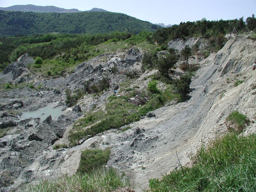
Downloaded from http://egsp.lyellcollection.org/ by guest on April 26, 2021

4                                                      INTRODUCTION

                      Fig. 1.3. The importance of geological time (after Fookes 1990; Fookes et al. 1997a, b).

the great depth encountered during the Lötschberg Tunnel           reactivation of solifluction shear surfaces that developed
disaster.                                                          during this case history, conventional soil mechanics could
   The scale of Pleistocene glacial processes is now widely        not explain landslides at such shallow slope angles. The
recognized and Lötschberg (Case History 1.1) marked just           understanding developed by the engineers in Case History
one step forward in the glacial sciences, albeit an unfortu-       1.2, and crucially communicated effectively to the industry,
nately expensive and tragic step. Nearly 60 years after the        allowed the teams working on the M25 motorway around
Lötschberg tunnel disaster, Case History 1.2 marked another        London to have an awareness of the potential existence of
important step forward, this time in understanding the influ-       relict periglacial shear surfaces. The occurrence and effects
ence of periglacial processes on the landscape in which engi-      on M25 engineering works, where such shear surfaces were
neering was taking place. Prior to the understanding of            encountered at Denham Corner, Buckinghamshire and Flint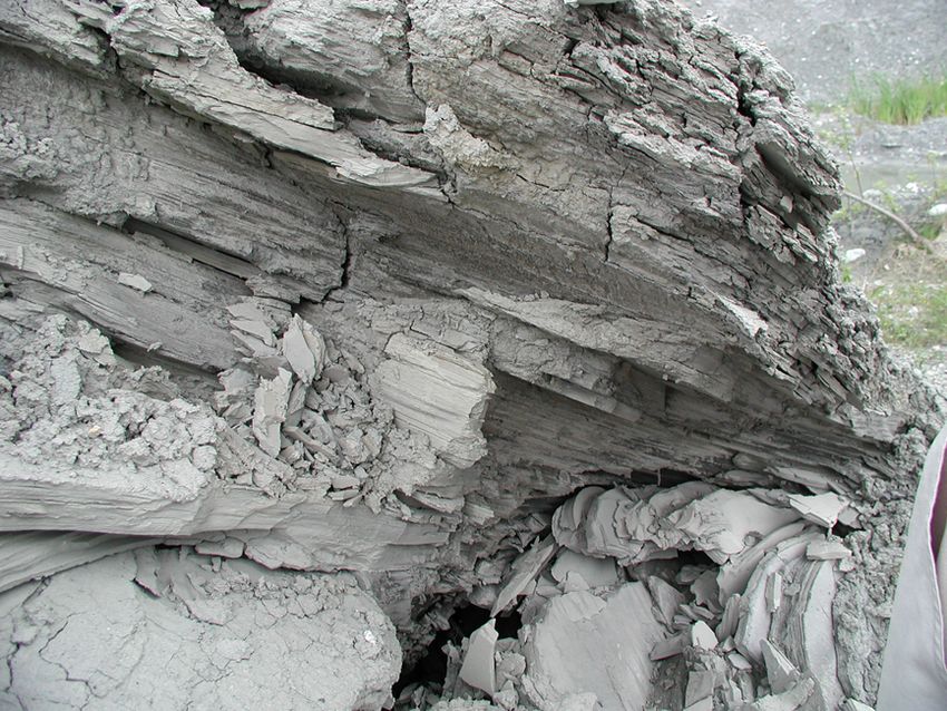
Downloaded from http://egsp.lyellcollection.org/ by guest on April 26, 2021
INTRODUCTION 5
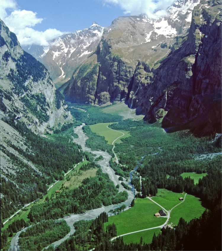
Case History 1.1: A glacially over-deepened valley and a tunnel heading in
Switzerland, by Tony Waltham (Consultant, Nottingham, UK)
The Lötschberg Tunnel disaster in 1908 in Switzerland was an engineering catastrophe caused by a simple lack of con-
temporary understanding of glacial processes (Waltham 2007, 2008, 2009). Nearly 14 km long, the tunnel was designed
to carry a railway beneath the crest of the Bernese Oberland. The alignment was determined by topography, providing the
shortest link at an attainable altitude between the Kander Valley on the north side and the Lonza Gorge on the south side.
By a quirk of the Kander’s own alignment, the tunnel would have to pass directly beneath an upper section of the valley
known as the Gasterntal (Fig. 1.4).
It was a bold engineering project and was only the third of the great Alpine railway tunnels, following in the wake of
the Gotthard and Simplon (Kovari & Fechtig 2000). However, at that time tunnelling capabilities were far ahead of
the knowledge base of the geological sciences. Less than 100 years previously there was no concept that Alpine land-
scapes and valleys had been excavated, or at least modified, by glaciers that had been far more extensive than their modest
descendants still surviving around the higher Alpine peaks. Moreover, nobody really understood that glaciers could
move uphill.
Fig. 1.4. The glaciated trough of the Gasterntal, looking up-valley from the Stock hill; the 1908 tunnel breakthrough created a valley-floor
sinkhole in the woodland just beyond the furthest of the large open meadows (© Tony Waltham Geophotos Ltd).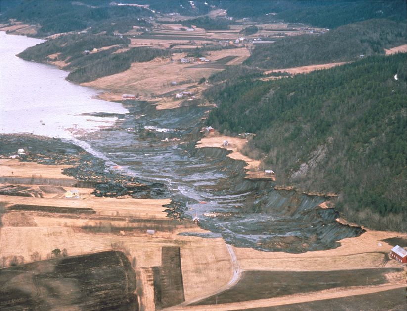
Downloaded from http://egsp.lyellcollection.org/ by guest on April 26, 2021

6                                                          INTRODUCTION

       Some 3 km in from its northern portal, the Lötschberg Tunnel had to pass beneath the floor of the Gasterntal at a depth
    of 172 m (Fig. 1.5). The flat floor of that valley is very clearly filled with alluvium, but the idea of alluvial sediments being
    more than 172 m deep was beyond any concepts of the current geological thought. Furthermore, downstream of the tunnel
    crossing, the Gasterntal narrowed into the Klus Gorge, where a bedrock valley floor is visible at an altitude only a few
    metres lower than that of the river above the tunnel. Questions were raised about the depth of the sediments on the tunnel
    line, but concerns were allayed because no-one could conceive of a valley floor increasing in elevation by 180 m in the
    downstream direction. A commission of geologists, perhaps politically motivated, concluded that there was no danger to
    the tunnel and dissenting voices from elsewhere were quietly suppressed.
       A borehole nearly 180 m deep into sediment would have been a difficult operation at that time, and was regarded as
    being excessively cautious and too expensive. Surprisingly, the obvious precaution of using advance probes from the
    heading when approaching the Gasterntal’s margin was not included as a design feature. Consequently, the tunnel
    face was advanced by conventional drill-and-blast. On 24 July 1908, a routine blast removed the last bit of rock and pre-
    cipitated a massive inrush of saturated gravels that had formed the sediment fill in the over-deepened Gasterntal. The ava-
    lanche of sand, gravel, mud and water ran down the tunnel for more than a kilometre, killing all 25 miners in the face team.
    The water soon drained out, and the sediment formed a very solid plug. A diverted tunnel heading curved around the
    Gasterntal and successfully met the opposite heading nearly 3 years later. The new sinkhole and whirlpool on the
    floor of the Gasterntal was soon filled by the river and lost to sight.

    Fig. 1.5. Plan and profiles of the Gasterntal and Klus Gorge (through the abandoned tunnel heading) around the Lötschberg Tunnel site
    (© Tony Waltham Geophotos Ltd).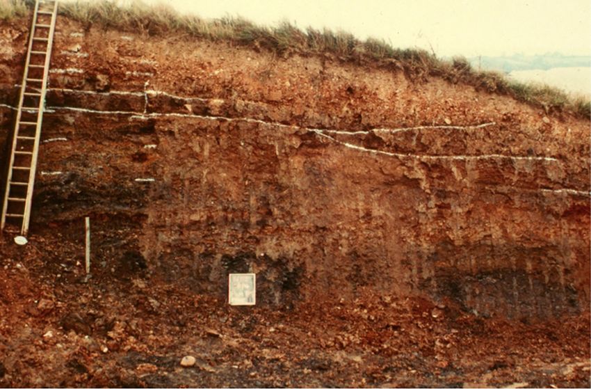
Downloaded from http://egsp.lyellcollection.org/ by guest on April 26, 2021

                                                     INTRODUCTION                                                              7

   The Lötschberg Tunnel made a classic breach of unmapped rockhead. Unfortunately this was into a hugely over-
deepened glaciated trough, which is effectively a very deep buried valley. Boreholes subsequently placed into the Gas-
terntal floor found unconsolidated sediments of more than 220 m in depth. Since then, even deeper sediment fills have
been found in glaciated valleys within mountain chains elsewhere in the world. The new Lötschberg Base Tunnel has
been more recently driven safely beneath the Gasterntal, at a level some 400 m below the original railway tunnel.

     Case History 1.2: The first identification of solifluction shear surfaces at low
               slope angles, Sevenoaks Bypass, Kent, by Keith Gabriel
                       (Gabriel GeoConsulting Ltd, Kent, UK)
The slope failures that occurred in 1965 during the construction of the Sevenoaks Bypass in Kent, UK led to a new under-
standing of the behaviour and geotechnical properties of clay slopes (Weeks 1969, 1970; Skempton & Weeks 1976). The
failures occurred in the natural ground during earthworks construction on the south-facing scarp slope of the Greensand
Ridge that lies just to the south of the North Downs in Kent. The Greensand escarpment is part of the eroded Wealden
Anticlinorium and comprises the Cretaceous-age Hythe Formation overlying clays of the Atherfield Clay and Weald Clay
formations. The Hythe Formation is made up of Ragstone, typically a strong sandy limestone, interbedded with Hassock,
which is a weak calcareous sandstone. The relatively competent Hythe Formation was affected by large-scale rotational
landslides; however, it was the relict solifluction lobes overlying both the in situ and landslide-displaced bedrock that the
original alignment cut through, and it was these that were reactivated during the construction works.
   The detailed ground investigations carried out after the failures identified two solifluction sheets at the site, the upper
4 m thick and the lower c. 3 m thick, together comprising a clayey head. The lower solifluction sheet directly overlay
in situ Weald Clay. The upper solifluction sheet ended in a distinct lobe about 400 m from the scarp slope, and where

                    Fig. 1.6. Plan and section through solifluction lobe (modified from Brunsden et al. 1988).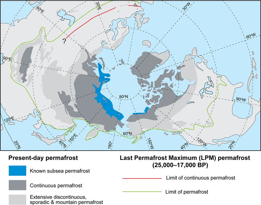
Downloaded from http://egsp.lyellcollection.org/ by guest on April 26, 2021
8 INTRODUCTION
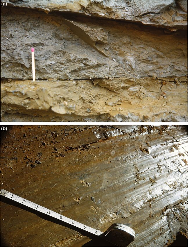
Fig. 1.7. Pit F2, Sevenoaks bypass (modified from Skempton & Weeks 1976): (a) shear surfaces in Pit F2; and (b) polished shear surface
in Pit F2 (Weeks 1969).
the earthworks failure occurred the slope angle was just over 3°. Solifluction is the term used to describe a combination of
two slow geomorphological processes, namely soil creep and gelifluction (slow soil flow associated with thawing ground;
Ballantyne & Harris 1994). However, trial pits in the solifluction deposits revealed extensive pre-existing shear surfaces at
low slope angles parallel and sub-parallel to the ground surface (Figs 1.6 and 1.7a, b). Based on this evidence it appears
that the slides at Sevenoaks were the much more rapid ‘active-layer detachment slides’ (Lewkowicz 1990) reactivated by
the road excavations, although the literature does refer to the failures as being reactivated solifluction lobes. This type of
slide develops when thawing of the active layer in the permafrost occurs very rapidly. Between the two solifluction sheets
was a palaeosol that was dated at a radiocarbon age of 12 ± 0.2 ka BP; this indicates that the upper sheet accumulated
during the Loch Lomond stadial whereas the older sheet would have formed earlier during the Devensian.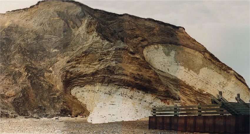
Downloaded from http://egsp.lyellcollection.org/ by guest on April 26, 2021

                                                       INTRODUCTION                                                              9

     Following the failures, stability analyses were undertaken using measured residual shear strength parameters; these
  predicted that the critical slope for sliding when the ground was fully saturated was between 6 and 8°. As solifluction
  involves the movement downslope of saturated soil it is especially effective in over-consolidated clays when the
  whole active layer detaches itself and slides over frozen ground at depth, thereby creating the extensive, broadly slope-
  parallel slip surfaces towards the base of each solifluction lobe or sheet. Detachment slides of solifluction sheets have been
  recorded on slopes as low as 3° to the south of Sevenoaks and up to 4 km from the Hythe escarpment. In the publication
  following the failure, Weeks (1969) hypothesized that frozen ground may have sealed in groundwater and thus impeded
  the drainage, building up excess porewater pressures. However, it is now recognized that the mechanism that enables a
  solifluction slip mass to move down such very shallow slopes, as first identified at Sevenoaks, involves the development
  of abnormally high porewater pressures during thaw of segregated ice at the base of the active layer and/or top of the
  permafrost in late summer (see Chapter 5). The frozen ground surface allows piezometric pressures to develop above
  ground level in the trapped saturated soils.
     Under present-day conditions, most undisturbed relict soliflucted slopes in over-consolidated clays are only likely to be
  unstable in winter when groundwater levels/pressures reach ground level, but are not a widespread phenomenon. The
  limiting slope angles have been shown to be approximately half the residual shear strength of the clay concerned, except
  where the slip mass is under-drained. However, small excavations into or additions of fill on these slopes can initiate fail-
  ures. The general pattern of shallow periglacial landsliding that was first identified at Sevenoaks was shown by Hutch-
  inson (1991) to be found over much of the outcrop of argillaceous bedrock in southern Britain.

Hall, Surrey are described in case studies 9.15 and 9.16 in        was either not recognized or underestimated, causing an
Chapter 9.                                                         embankment dam failure. At Carsington it was the reactiva-
   The landsliding that occurred at Sevenoaks in 1965 was of       tion of movement along periglacial shear surfaces during
considerable size and was moving at a speed that was detect-       the construction of the dam in 1984 that occurred, and this
able without instrumentation. The landsliding occurred on          was nearly 20 years after the 1965 failure at Sevenoaks
soils that were much more sensitive to changes in porewater        reported in Case History 1.2. Clearly, the lesson that residual
pressure and loading regime than was previously understood.        shear surfaces might exist in soliflucted material had not
However, the landslide that occurred at Rissa, Norway in           become embedded in ground model development and ground
1978 (Case History 1.3) demonstrated a scale and speed of          investigation design at that time. In geotechnical engineering
movement that was a number of orders of magnitude greater          there was also a lack of appreciation of the importance and
than occurred at Sevenoaks. At Rissa the landslide swept           extent of relict periglacial conditions in the specific locality.
away an area of around 330 000 m2 over a total time of                Contrasting with the situation at Carsington (Case History
about 40 min (Gregersen 1981). The open texture of the             1.5), in Case History 1.6 the highly sensitive and variable
metastable quick clay that formed this landslide was highly        ground along the proposed alignment of the A51 Grenoble
sensitive to minor changes of load and associated pore pres-       to Sisteron Autoroute was recognized, and had impacted on
sure increases. The ratio of the strength of the ‘remoulded’       route selection since the 1960s (Martin et al. 2005). The con-
quick clay compared to intact quick clay is now routinely          struction of this autoroute has been controversial since the
investigated in areas where the clay occurs. The quick clay        first section was built in 1953 (Martin et al. 2005) due to
was laid down in a glaciomarine environment and, while lim-        the design, cost and environmental impact of the road that
ited in spatial extent, the deposit represents a very significant   was partly influenced by the glacial ground conditions. The
natural hazard.                                                    problematic ground conditions were the product of deposits
   While at Rissa the deposits that failed were glaciomarine,      laid down in a large ice-dammed glacial lake which included
in Case History 1.4 from Volgodonsk in Russia it was another       glaciolacustrine silt and clay sequences interbedded with both
form of open-textured metastable deposit that collapsed. In        subglacial till and supraglacial diamicton. These highly vari-
this case the foundation materials were wind-blown loess           able deposits were prone to instability, including slope and
and construction loading in the early 1980s resulted in the        bearing capacity failure, differential settlement and liquefac-
sudden loss of strength of the ground. Although the wind-          tion. Their problematic nature, especially their propensity to
blown loess ground conditions found at Volgodonsk were             liquefaction, had the potential to significantly impact the
initially recognized as collapse-prone soil, considerable addi-    integrity of embankments and cuttings along the road align-
tional losses were incurred due to differential settlement. A      ment. The targeted ground investigation and ground model
change from the proposed piled foundation to a shallow foun-       were developed from the century-old knowledge advances
dation solution in these sensitive soils as a measure to save      in the geological sciences, combined with experiences from
construction costs did not pay off, even with an attempt at        some of the costly mistakes highlighted in such case histories
groundwater control.                                               reviewed above.
   In Case History 1.5 (Carsington Dam, UK), as at Volgo-             An important aspect of the glacial and periglacial environ-
donsk and Sevenoaks the impact of the ground conditions            ment during Quaternary stadials is that they were associated
Downloaded from http://egsp.lyellcollection.org/ by guest on April 26, 2021

10                                                        INTRODUCTION

     Case History 1.3: Landslide in quick clay at Rissa, Norway, 1978 (Gregersen 1981)
                       by Jim Griffiths (University of Plymouth, UK)
     ‘Quick’ clays are sensitive marine or brackish-water sediments, generally deposited in late-glacial and postglacial periods.
     Leaching of salt from the deposit leads to a significant reduction in its remoulded strength so that when they are disturbed
     they behave as a liquid. Quick clays were mostly deposited during ice-sheet recession at the close of the last Deven-
     sian/Weichselian/Wisconsinan glaciations, and are normally 10 km/hour. Not only did the landslide erode headwards from
     the lake, it also caused great damage to the community of Leira when a 3 m high seiche wave reached the opposite
     bank of the lake, representing a significant secondary hazard.
        According to Torrance (2012) quick clay ‘exhibit a wide range of strengths, sensitivities, clay-size contents, relative
     mineral abundances and geotechnical behaviours’. One of the main ways to avoid failures such as Rissa 1978 is to identify
     the extent of quick clay deposits through effective ground investigation and undertake probabilistic risk assessment
     (Cassidy et al. 2008). Nevertheless, approaches using injected saline solutions have been devised that strengthen the
     deposits in situ with some success (Moum et al. 1968).

     Fig. 1.8. Rissa Slide overview, Norway, 29 April 1978 (© NTB Scanpix and NGI (Norwegian Geotechnical Institute) and reproduced
     with their permission).
Downloaded from http://egsp.lyellcollection.org/ by guest on April 26, 2021
INTRODUCTION 11
with lower sea levels and therefore exist in areas of the con- Seven case histories have been presented, demonstrating
tinental shelf now covered by shallow seas. The design and the complexity and variability of ground conditions associ-
investigation of all offshore infrastructure development ated with formerly glaciated and periglaciated environments.
need to take this into account. Case History 1.7 presents the Although the case histories were chosen to demonstrate how
findings of an offshore ground investigation carried out in these ground conditions have adversely impacted on the
2010 and, as with the example from the A51 Autoroute engineering solutions, they also demonstrate an increasing
(Case History 1.6), this more recent case history demonstrates understanding and advancing awareness of these ground
a developing awareness of the complexity of the ground asso- conditions and their implications with time. Case History
ciated with former glacial conditions. The project team work- 1.1, the Lötschberg tunnel disaster, was undertaken when
ing on the offshore ground investigation in the North Sea the understanding of glacial processes on the terrain was
were able to build on an understanding of potential variability incomplete; although a ground investigation was undertaken,
of the ground in that environment, and sought examples of it was insufficient and limited by the knowledge of the day.
nearby similar terrestrial ground conditions to validate their Hutchinson & Fookes (2004) note that, particularly from
ground model. the 1960s onwards, studies of Quaternary geoscience
Case History 1.4: Residential apartment blocks constructed on loess, Volgodonsk,
Rostov Oblast, Russia, by Stephen Fort (Atkins, London, UK)
Foundation problems were reported relating to the construction of dozens of high-rise residential buildings in the early
1980s in Volgodonsk in the Rostov Oblast region of Russia. Loess deposits up to 20 m thick underlie the site and exhib-
ited what was described as a ‘Type II collapsible behaviour’. Russian practice is to categorize collapsible soils into Type I
and II according to their code of practice (SNiP 2.02.01-83 1985). Type I soils undergo collapse when wetted only if also
subjected to additional loading (e.g. building loads). Type II soils when wetted undergo significant collapse under self-
weight alone. The magnitude of self-weight collapse of Type II soils may be significantly greater than for Type I soils
throughout the full depth of the collapsible soil stratum.
Volgodonsk is situated on the 4th terrace and slopes of the River Don. The loess deposits are understood
to typically comprise coarse to medium silt (47%) and fine silt and clay (46%), with a natural moisture content of
17%, a bulk density of 1.80 Mg m−3 and porosity of 43%
(Trofimov et al. 2015).
The development at Volgodonsk included two nine-
storey residential blocks, which were commissioned in
1982 (Fig. 1.9). The initial concept was for these buildings
to be founded on piles; however, in order to save construc-
tion costs, the foundations were changed to shallow rein-
forced cast in situ concrete crossed ground beams resting
on 3 m depth of recompacted soil. At the same time,
unspecified collapse and water control measures were
implemented, but these proved to be ineffective.
After about a year of occupation, settlement problems
of the blocks became apparent. Grigorian (1991, 1997)
reported the cause of this being due to top-down wetting
caused by defective water utilities. This uneven wetting
of the collapsible loess resulted in differential settlements
of up to 1 m, with tilting of buildings exceeding 0.009
(1/111). A number of the buildings had to be evacuated
and extensive repairs undertaken. High-rise buildings in
Volgodonsk have subsequently been constructed using
pile foundations through the full thickness of the collaps-
ible soils. No further settlement problems have been
reported. Total financial losses from loess subsidence in
Volgodonsk reached US$ 400 million by 1996 (Exogenous
Geological Hazards 2002). Fig. 1.9. Two nine-storey residential blocks in Volgodonsk.Downloaded from http://egsp.lyellcollection.org/ by guest on April 26, 2021
12 INTRODUCTION
Case History 1.5: Reactivation of periglacial shear surfaces resulting in embankment
dam failure, by David Norbury (David Norbury Ltd, UK)
An embankment dam was to be constructed 3 km south of the village of Carsington, Derbyshire, UK. An extensive
ground investigation was carried out, but failed to recognize the periglacial features. Consequently, the embankment
failed during construction in June 1984 and then had to be demolished and rebuilt to a design based on the correctly under-
stood ground conditions. The reconstruction was successfully completed, but at a considerable cost and delay to the cli-
ent. The finished reservoir was opened in 1992.
The site lies in a broad valley with an alluvial floodplain up to 80 m wide. Bedrock is Upper Carboniferous (Namurian)
mudstone with occasional thin bands of sandstone. Till up to about 5 m thick and patches of glaciofluvial gravel exist on
the neighbouring higher ground.
The valley side slopes, typically inclined at 4–6°, are mantled by a layer of head (i.e. periglacial slope deposits) aver-
aging 1.2 m in thickness. A typical profile through the head deposits (Fig. 1.10) reveals topsoil and a silty subsoil (al) over-
lying a plastic yellow-brown mottled clay (a2), containing scattered fragments of sandstone and rare quartz pebbles derived
from the glacial deposits. The head overlies a layer of completely weathered mudstone (bl) almost identical to a2 except that
it has no ‘foreign’ inclusions (Skempton et al. 1991). For geotechnical purposes a2 and b1 can be classed together as ‘Yel-
low Clay’. Below this, the weathered mudstone is dark grey in colour and changes with depth from clay (b3) to a brecciated
material (b4) and then to an extremely weak mudstone (b5). Weathering extends to a depth of over 10 m. Anomalous super-
ficial folding of these materials was also noted at sev-
eral locations, probably also the result of periglacial
freeze and thaw processes (Aitkenhead 1984).
The downslope movement of the head (probably
representing the active layer under permafrost con-
ditions) gave rise to shear surfaces at or below the
junction of a2 and b1 and sub-parallel to the ground
slope (Figs 1.11 and 1.12). The shear surfaces are
smooth, unpolished, gleyed, undulating and have a
characteristic length of about 3 m. On average they
occupy 40% of the total length (56 m) of sheared
ground examined.
The individual shear zones were up to 2 mm in
thickness and comprised clay mineral aggregates
aligned sub-parallel to the shear surface; the aggre-
gates outside the shear zones were randomly oriented.
It is important to note that identification of these shears
in freshly excavated clay was not possible; the clay
had to be allowed to dry out for several weeks to be
observed. This has important repercussions in site
Fig. 1.10. Typical transported and weathered soil profile. investigation practice in such circumstances.
Fig. 1.11. Logged section through head and in situ mudstone.Downloaded from http://egsp.lyellcollection.org/ by guest on April 26, 2021
INTRODUCTION 13
Fig. 1.12. Photograph of logged section shown in Figure 1.11.
The presence of solifluction shears will reduce the overall or bulk strength of the Yellow Clay. Residual strength on the
shear surfaces is reached before the peak strength of the unsheared clay is developed (Skempton & Petley 1967). Con-
sequently, the peak parameters for the layer as a whole will be c′ = 6 kPa, ϕ′ = 17°. The peak bulk strength is then about
14% lower than that of the intact clay; such a reduction would for example cause a factor of safety of 1.5, based on intact
strength, to fall to 1.29. This reduction could be further increased by a tendency for progressive failure; at Carsington the
combined effects on the Yellow Clay produced a reduction of about 22% in the factor of safety (Skempton 1988) and
failure of the embankment resulted.
Case History 1.6: A51 Grenoble to Sisteron Autoroute through former glacial Lac de
Trièves, by David Giles (University of Portsmouth, UK)
The A51 Autoroute was commissioned to provide a relief road for the A6 Rhone Corridor motorway which connects Paris
to the holiday regions of the south of France. The last remaining component of the Autoroute was the section between
Grenoble and Sisteron. This section was to pass through the highly problematic ground conditions of the Trièves area and
had been the subject of many investigations and research since the 1960s, before a final route alignment was selected and
agreed upon (Martin et al. 2005). Even at the construction tender stage this section remained controversial with several
initial design proposals being rejected because of the uncertainty in the ground conditions, specifically with regard to the
nature of the glaciolacustrine and till sequences.
During the last period of maximum glacial advance in the Trièves region (late Weichselian), a large ice-dammed
glacial lake developed which gradually infilled with glaciolacustrine silt and clay sequences (including laminated
‘varved clays’) and interbedded till sequences representing ice readvances (Fig. 1.13). These deposits rest on older
Eemian Interglacial sediments and on underlying Jurassic carbonate-dominated bedrock (Jongmans et al. 2008).
The thickness of the glaciolacustrine deposits varies between less than 0.1 m and a maximum of 200 m. These sed-
iments are highly prone to instability and have given rise to some spectacular rotational mudslides and subsequent
mudflows in the area (Fig. 1.14). In detail, the differing facies associated with the former glaciolacustrine environ-
ment include rhythmically laminated silt and clay sequences, deeper water turbidites and ice-rafted debris
(Fig. 1.15). These are interbedded with both subglacial tills and supraglacial mass flow diamictons, demonstratingDownloaded from http://egsp.lyellcollection.org/ by guest on April 26, 2021
14 INTRODUCTION
Fig. 1.13. Extent of the glaciers at the Weichselian Maximum (equivalent to the Late Devensian in the British Isles; see Chapter 2) and
location of the major proglacial lakes (after Monjuvent 1973).
the highly dynamic nature of the former ice-contact glacial depositional environment. The spatial distribution and
geotechnical properties of the glaciolacustrine silts and clays have been extensively investigated with respect to
the potential alignments of the A51 Autoroute (Giraud et al. 1991). Their problematic nature, especially their propen-
sity to liquefaction, has the potential to significantly impact on the integrity of embankments and cuts along the
road alignment.
The existing river system and drainage network also presented difficulties for the route alignment. The site topography
required a large fill section with embankments to be constructed for access to the northern tunnel portal. The maximum
height of the fill section reaches 17 m above the original ground level. The substrata at the base of the embankment section
vary between the Trièves glaciolacustrine deposits and the limestones of the main slope. The geotechnical profile of the
foundation strata of the fill section was complex with a strong contrast between the ground conditions at either end of the
embankment. The limestone bedrock of the slope was covered by a substantial thickness of superficial deposits such as
moraine ice debris along with the varved clay/silts of Trièves.
The geotechnical risks were considerable at this particular location. Slope failures or bearing capacity failure of the
glaciolacustrine clays were potential problems, along with differential settlement. The ground conditions were quite var-
iable, including the potential for the sensitive clays and silts to liquefy and flow. Geotechnical testing was undertaken to
profile the ground conditions, and included pressuremeter tests, penetrometer tests and an in situ direct shear test known
as a phicometric test (Monnet 2015). These in situ investigations were complemented by laboratory tests including full
geotechnical description, triaxial compression tests and oedometer tests to profile the compressibility and creep charac-
teristics of the glaciolacustrine deposits. Studies undertaken on the stability of the embankment yielded theDownloaded from http://egsp.lyellcollection.org/ by guest on April 26, 2021
INTRODUCTION 15
Fig. 1.14. The landslide complex at Harmallière in the Sinard sector (figure on extreme right indicates scale).
Fig. 1.15. Glaciolacustrine sediments of the former Lac du Trièves (image shows an approximate 1.5 m section).Downloaded from http://egsp.lyellcollection.org/ by guest on April 26, 2021
16 INTRODUCTION
Fig. 1.16. Typical cross-section of embankment with work schedule (after Martin et al. 2005).
following parameters. Undrained shear strength: Su = 65 kPa for 0–2.50 m; Su = 70 kPa for 2.5–13 m; and Su = 85 kPa for
>13 m. Coefficient of consolidation: cv = 1.6 × 10⁻⁷ m2 s−1; and cr = 8 × 10⁻⁷ m2 s−1.
Slope stabilization and embankment construction works were phased as shown in Figure 1.16. In this case history, the
long period of investigation and extensive ground investigations had enabled the scale of the risk to be correctly evaluated
and the geotechnical designs had been able to allow for the difficult ground conditions. This demonstrates the increasing
awareness of the complexity of ground conditions in formerly glaciated and periglaciated terrain.
Case History 1.7: Glaciotectonic raft of Chalk interpreted during an offshore ground
investigation, southern North Sea, UK, by Christopher Kilsby (Atkins, Epsom, UK)
A geotechnical ground investigation was undertaken in the Outer Wash to gain a better understanding of the geological
conditions and geotechnical parameters at a proposed offshore wind farm. The ground conditions comprise Upper Cre-
taceous Chalk overlain by Pleistocene glacial and interglacial formations. In turn, these are overlain by a variable thick-
ness of Holocene seabed sediments. The water depth across the site varies over the range 6–26 m.
A schematic cross-section of the Outer Wash highlighting the presence of infilled tunnel valleys and the lateral vari-
ability of units is shown in Figure 1.17 (British Geological Survey 1991). Information on the geology of the Outer Wash is
provided by Cameron et al. (1992).
During the ground investigation which was undertaken in 2010, a tunnel valley was interpreted to cross the site in a
north–south direction. At its maximum, the floor of the tunnel valley was identified in boreholes at 55 m below ground
level. Interpreted to have been eroded into the chalk during the Anglian Glacial Stage, the tunnel valley was subsequently
infilled with till of the Swarte Bank Formation.
A borehole located near the mid-point of the tunnel valley encountered a 7 m thick sequence of intact chalk within the
Swarte Bank Formation, as summarized in Table 1.1. The intact chalk was interpreted as a glaciotectonic raft that had
been detached from the bedrock beneath the Anglian Stage ice sheet, and then transported and deposited within the
till (Swarte Bank Formation) that infills the tunnel valley.
Glacial rafts are widely recognized in glaciogenic sequences (e.g. Christiansen 1971; Moran 1971; Ruszczynska-
Szenajch 1976, 1987; Stalker & Mac 1976; Ringberg et al. 1984; Aber et al. 1989; Hopson 1995; Burke et al. 2009) andDownloaded from http://egsp.lyellcollection.org/ by guest on April 26, 2021
INTRODUCTION 17
Fig. 1.17. Schematic cross-section for the Outer Wash, showing the ground conditions interpreted by the British Geological Survey
(1991). tk, Undivided Mesozoic Strata (chalk); SBK, Swarte Bank Formation; EG, Egmond Ground Formation; BDK, Bolders Bank
Formation; BCT, Botney Cut Formation; qh, Holocene Sediments (note that at this time the BGS were still using the term ‘drift’ to
describe Quaternary sediments).
Table 1.1. Summary log of the borehole that encountered the interpreted glaciotectonic raft
Depth below seabed (m) Formation Geotechnical description
0–32 Various Various
32–39 Swarte Bank Formation Hard grey sandy gravelly CLAY. Gravel is fine to medium,
mainly of chalk
39–46 Chalk Very weak to weak low-density white CHALK
(CIRIA* Grade B2) (interpreted as raft of chalk)
46–55 Swarte Bank Formation Very stiff grey slightly silty CLAY
55–73 (end of borehole) Chalk Very weak low-density white to light-grey CHALK
(CIRIA Grade Dm) (interpreted as in situ chalk)
Note that the strata above the Swarte Bank Formation have not been detailed for brevity (Lord et al. 2002).
Fig. 1.18. Rafts of chalk emplaced within shallow marine sands and gravels of the Wroxham Crag Formation, exposed in the cliff face at
Sidestrand, Norfolk; the upper raft is about 10 m thick measured vertically (photograph from The Northfolk Project 2015).Downloaded from http://egsp.lyellcollection.org/ by guest on April 26, 2021
18 INTRODUCTION
are defined as ‘dislocated slabs of bedrock and/or unconsolidated sedimentary strata that have been transported from their
original position by glacial action’ (Ruszczynska-Szenajch 1987).
The glacial raft was encountered in only one borehole and the project’s geophysical survey could not determine its size.
No dating of the chalk was undertaken to help determine where the chalk raft could have been transported from; however,
as the chalk was logged as intact, it may only have been transported a short distance (perhaps in a frozen state).
An onshore example of glaciotectonic rafts of chalk is exposed in the coastal cliff at Sidestrand, Norfolk (Fig. 1.18).
The rafts are approximately 50 km from the offshore windfarm site, and may be of a similar size to that interpreted to have
been encountered at site. However, differences in the host material exist between these two examples: the Sidestrand raft
had been deformed within the marine sands and gravels of the Wroxham Crag Formation, while the Outer Wash raft had
been deformed within and deposited with till of the Swarte Bank Formation. This case history illustrates how difficult it
can be to define bedrock suitable for foundations in glacial materials. Exploratory holes in ground investigations need to
be taken to depths that enable displaced bedrock rafts to be identified or discounted and, if possible, the extent of any
glacial rafts should be established through geophysical investigations.
expanded exponentially; this coincided with the leap in Clarke (2012). EGGS therefore decided that the topic
understanding related to reactivated palaeo-shears, developed would benefit from an update to incorporate the wealth of
from the detailed investigation into the landslide that academic advances and professional experience acquired in
occurred at Sevenoaks in 1965 (Case History 1.2). At this recent years.
time, fast-paced developments in Quaternary geoscience Following a recommendation by the Hot Deserts Working
were running alongside developments in soil mechanics. Les- Party (Walker 2012) and endorsement by EGGS, a Steering
sons were learnt from the spectacular failures at Rissa (Case Group was established in November 2010 to explore the
History 1.3), Volgodonsk (Case History 1.4) and Carsington options for a new Working Party on Periglacial and Glacial
Dam (Case History 1.5). The knowledge of these failures and Engineering Geology. This new Working Party would be
advances in understanding have been employed to develop tasked with producing a book in the form of this Engineering
more robust ground investigations, and this is illustrated in Geology Special Publication (EGSP) on the Engineering
case histories 1.6 and 1.7. The result of the increasing under- Geology and Geomorphology of Glaciated and Periglaciated
standing of ground conditions in these formerly glaciated and Terrains. It is intended that this book will provide essential
periglaciated environments has resulted in very successful guidance for engineering geomorphologists, engineering
engineering projects in these complex ground conditions; geologists and geotechnical engineers working in such prob-
examples are presented throughout this book and specifically lematic ground conditions. This new book is also intended to
in Chapter 9. Reflecting on the case histories presented in this complement guidance on other types of problematic ground
first chapter, it is possible to see the growing realization for a conditions associated with tropical residual soils (Fookes
holistic approach to understand the natural complexity of the 1990, 1997a, b) and hot deserts environments (Walker 2012).
materials and processes encountered in glacial and periglacial The Steering Group comprised Mr John Charman (Chair),
environments. Physical geography, Quaternary studies and Mr Chris Martin (Secretary), Dr Dave Giles, Professor James
stratigraphy, engineering geology, hydrogeology, soil and Griffiths, Professor Julian Murton, Dr Kevin Privett and
rock mechanics, geotechnical design and construction all Professor Mike Winter. The Steering Group met three times
have a contribution to make in this field of work (Bell 2007). in 2010 and 2011, with key outputs including a Publication
Proposal and draft Terms of Reference for the Working
Party (Text Box 1.1). The outline of the Publication Proposal
was presented and ratified at the EGGS Forum on Quaternary
1.3 The Working Party Engineering Geology on 24 November 2011, where it
received extremely positive support from the wider geogra-
1.3.1 Background phy, engineering geology and geotechnical engineering
communities. The Publication Proposal was subsequently
The topic of the 25th Annual Conference of the Engineering approved by the Geological Society Executive Secretary
Group of the Geological Society (EGGS) in 1989 was ‘Qua- and the Geological Society Publishing House.
ternary Engineering Geology’, with the proceedings being
published in the extremely popular Engineering Geology 1.3.2 Membership
Special Publication no. 7 (Forster et al. 1991). As a collection
of papers, this has proved to be a very useful source of infor- Members of the Working Party (Fig. 1.19) were drawn from
mation for engineering geological academics and practition- individuals with known periglacial and glacial engineering
ers alike; however, very little engineering geological research geological expertise from across academia and engineering
has been carried out into the subject since the conference, as practice, including geomorphologists, engineering geologists
indicated by reference to later works by Trenter (1999) and and geotechnical engineers.Downloaded from http://egsp.lyellcollection.org/ by guest on April 26, 2021
INTRODUCTION 19
Fig. 1.19. The Working Party at Burlington House, June 2016. From left to right: Sven Lukas, Julian Murton, David Norbury, Martin Culshaw,
Dave Evans, Jim Griffiths, Anna Morley, Mike Winter, Dave Giles, Mike De Freitas and Chris Martin (Chair).
The Working Party was led by three officers: Mr Christo- reviewed each chapter to ensure that the book is clear and
pher Martin as Chairman and Co-Editor; Professor James scientifically rigorous.
Griffiths as Lead Editor; and Mrs Anna Morley as Secretary. The first meeting of the Working Party was held on 27
The Working Party also comprised the seven lead authors of February 2012. The Working Party held a further 12 meetings
Chapters 2–8 of this EGSP, namely Dr Sven Lukas, Dr David with the final meeting being held on 1 July 2015.
Giles, Professor David Evans, Professor Julian Murton, Dr Soon after inception of the Working Party, it became
Michael de Freitas, Professor Martin Culshaw and Professor apparent that there were significant differences in approach
Mike Winter. Professor David Norbury was later co-opted as being proposed and adopted by the geomorphologists and
a full Working Party member to provide specialist input on engineering geologists within the Working Party, especially
the identification and classification of soils that was funda- around the description and classification of soils and land-
mental to all chapters. forms. An aim of the Working Party was always to bridge
While each lead author was solely responsible for ensuring the gap between the latest scientific developments and the
the delivery of their respective chapter, they also enlisted experience and approaches adopted in engineering practice;
co-authors to draft subsections and provide case studies and two field meetings were therefore held to discuss and agree
contributions. Each chapter of the book has been reviewed a common language and methodology as a key output of
by other members of the Working Party, leading to a cross- the Working Party. The first field meeting was held on
fertilization of ideas and consistency of approach. The book 12–14 July 2013 to review the glacial deposits of the
has undoubtedly benefited from this collaborative working. East Yorkshire coast. A second field meeting was held on
In addition, an independent expert peer reviewer externally 16–18 May 2014 to review periglacial features in Kent.Downloaded from http://egsp.lyellcollection.org/ by guest on April 26, 2021
20 INTRODUCTION
Text Box 1.1: Terms of Reference of the Working Party
(1) These Terms of Reference are as agreed by the Periglacial and Glacial Engineering Geology Working Party
(PGEGWP).
(2) The PGEGWP has been established by the Engineering Group of the Geological Society and comprises officers and
specialist participating members who will act as lead authors. The participating members may be assisted by any
number of co-authors and corresponding members.
(3) The PGEGWP will produce a report, in book format, to complement the earlier report on Tropical Residual Soils
produced by an earlier Working Party of the Engineering Group, first published in 1990 and republished in book
format in 1997. A similar format was adopted by the Hot Deserts Working Party, which published their book in
2012. It is intended that the book will be a state-of-the-art review on the ground conditions associated with former
Quaternary periglacial and glacial environments and their materials, from an engineering geological viewpoint.
There will necessarily be appropriate coverage of the modern processes and environments that formed
these materials.
(4) It is not intended to define the geographic extent of former periglacial and glacial environments around the
world, but to concentrate on ground models that would be applicable to support the engineering geological
practitioner.
(5) The aim of the PGEGWP is to produce a book that will act as an essential reference handbook for professionals as
well as a valuable textbook for students and others. The style will be concise and digestible by the non-specialist, yet
be authoritative, up-to-date and extensively supported by data and collations of technical information. The use of
jargon will be minimized and necessary specialist terms will be defined in an extensive glossary. There will be copi-
ous illustrations, many of which will be original, and many good-quality photographs.
(6) The content of the report will embrace a full range of topics from the latest research findings to practical applications
of existing information. Likely directions of research and predictions of future developments will be highlighted
where appropriate. The book will be based on world-wide experience in periglacial and glacial terrain and will
draw upon the experience of its members and publications on periglacial and glacial conditions.
(7) The Working Party members will be collectively responsible for the whole book. Although each participating mem-
ber will be the named author or co-author of one or more chapters, all members will be expected to review and
contribute to the chapters drafted by other members and would be acknowledged as such. Individual book chapters
will be included in the Thomson Book Citation Index.
This ‘ground-truthing’ greatly aided the development of a on the engineering geology of inherited or relict glacial and
common approach. periglacial sediments and landforms needed well-defined
limits on its scope. Because of the nature of the subject,
these limits were difficult to establish and had to cover geo-
1.3.3 Objectives graphical extent, discipline boundaries and the needs of
The aim of this EGGS Working Party was to provide an potential users. The overriding criterion was that any material
authoritative state-of-the-art review from an engineering provided must meet the requirements of engineering geolo-
geological viewpoint on the ground conditions associated gists working in ground engineering to support the construc-
with former Quaternary periglacial and glacial environments tion industry. However, it was recognized that the book
including their materials, hazards and the approach to inves- would also contain a great deal of information relevant to
tigation, design and construction. Further details are provided regional and local planning, offshore exploration and devel-
in the Terms of Reference of the Working Party in Text opment, waste disposal, resource assessment and mining,
Box 1.1. These Terms of Reference were drafted by the Steer- and the water industry.
ing Group and ratified by the Working Party at their inaugural It was decided that while the Working Party book would
meeting. concentrate on engineering geology practice in the British
Isles, most of the material would be useable for projects
throughout NW Europe, including offshore areas such as the
North Sea and the Baltic. Indeed, the generic material in the
1.4 Scope of the report book was regarded as having application in all areas where
relict glacial and periglacial terrains have been identified,
During the early meetings of the original Steering Group and which includes North America, Northern Asia (mainly Rus-
subsequent Working Party, it became apparent that any book sia) and Southern Hemisphere countries such as Argentina,Downloaded from http://egsp.lyellcollection.org/ by guest on April 26, 2021
INTRODUCTION 21
Chile and New Zealand. By recognizing this broader scope, Period cold ‘stadials’. However, there has to be recognition of
the Working Party was able to draw on a wider range of liter- the concept of ‘deglaciation’, that is, when ice disappears
ature and case studies to support the research for the book. from a previously glaciated region. Following deglaciation
Active glacial and periglacial processes and the present- there will be a period when the natural landscape makes
day permafrost were seen as part of a completely different the transition from the glacial to non-glacial conditions, and
engineering geological investigative process, and deemed during this period geomorphological features will adjust to
as being beyond the scope of the book. Nevertheless, to the new post-glacial environment. This transition period
understand the formative mechanisms of relict deposits and has been labelled ‘paraglacial’ (Church & Ryder 1972; Bal-
landforms, the Working Party decided it would be necessary lantyne 2002a, b, 2003; Knight & Harrison 2009), and can
to provide analogues by referring to the geomorphological have significant engineering geological implications. For
processes that are active in present-day glacial and periglacial example, it takes the vegetation cover a considerable time
environments. By seeking actual examples of active glacial to establish following deglaciation which, coupled with
and periglacial processes, work from areas outside Europe high winds, can lead to the development of extensive loess
(notably from North America) was accessed. This is included deposits (Derbyshire & Meng 2005). Slope instability is a
in Chapters 3 (geomorphological background), 4 (glacial) particular issue during this period and Ballantyne (2002b,
and 5 (periglacial), but no attempt has been made to provide p. 371) states ‘deglaciation results in the exposure of unstable
a comprehensive treatise on glaciology or periglaciation as and metastable sediments’. Specific paraglacial slope insta-
these disciplines are already well served by existing literature. bility hazards resulting from these conditions were therefore
As a consequence of this decision, it was felt essential to pro- included in the book, notably quick clay failures, loess
vide a visual glossary to illustrate both the presently active liquefaction (or hydrocollapse) and periglacial solifluction
processes and existing sediments in juxtaposition with the movements. However, it was decided to exclude a detailed
relict forms that would be encountered by ground engineers. evaluation of other forms of mass movement as this topic is
This glossary is provided in Chapter 3 and one element was already covered in detail by existing literature (e.g. Turner
to establish a link between modern geomorphological termi- & Schuster 1996; Bromhead et al. 2000; Clague & Stead
nologies and longstanding engineering geological nomencla- 2012). It is accepted that many landslides would have
ture, along with recommendations for a lexicon that all parties occurred due to paraglacial processes such as the rock slope
should use in the future. This lexicon had to be based on the failures investigated by, for example, Shakesby & Matthews
requirements of Eurocode 7 and BS5930 (British Standards (1996), Jarman (2003, 2006, 2007, 2009) and Davies et al.
Institution 2015), but needed to accommodate the terminol- (2013) in the British mountain terrains and Norway, and
ogy employed by geomorphologists in their descriptions of these features remain in the present-day landscape. The iden-
glacial and periglacial sediments. A particular sedimentolog- tification of these relict features is an important component of
ical term geomorphologists employ is ‘diamicton’, which is a all engineering geological site investigations.
granular deposit with limited fine-grained material that engi- In addition to the Quaternary Period, there have been other
neering geologists would describe as either gap-graded or episodes of extensive glacial ice coverage identified in the
part of a soil sequence containing lenses/layers of different geological record, notably the Permo-Carboniferous Glacia-
grain-size materials. From numerous field discussions, the tion of the southern continent of Gondwanaland that lasted
engineering geologists in the Working Party came to the con- nearly 90 Ma (Visser 1987). An evaluation of the sediments
clusion that the present terminology in BS5930 was sufficient of these ancient glaciations (tillites) was excluded from the
for describing these materials for ground engineering, but book, as these were regarded as being more of geological
practitioners should be aware that there is an alternative than engineering geological interest and importance.
term being used in an adjunct discipline. Arising from discussions on the interface between geo-
The Quaternary Period covers the last 2.6 Ma of Earth his- morphology and engineering geology, one clear link was
tory and, while it is associated with the concept of the ‘ice found to be in the use of the concept of landsystems by both
ages’, for much of this time the climate was similar to the pre- disciplines as a means of understanding landscape develop-
sent day. The Quaternary Period therefore contains both ment and the spatial distribution and material composition
times of expanded glacial ice cover and ‘interglacials’ such of landforms (Evans 2013). A previous Engineering Geology
as the present Holocene Epoch, which commenced 11.7 ka Working Party (Griffiths 2001) recommended use of a land-
ago with the climatic amelioration at the end of the Younger systems approach as part of site investigations as it establishes
Dryas Stadial (see Chapter 2). Geomorphogical processes are the spatial and temporal complexity of landforms and helps to
active during interglacials as a function of the warmer cli- define boundary conditions, leading to an understanding of
matic conditions and changing sea levels. Typically, pro- the vertical and lateral variability of material properties. A
cesses in the interglacials include marine estuary infilling, landsystems methodology also lends itself to the creation of
inundation of offshore areas, coastal erosion and deposition engineering geological ground models (Parry et al. 2014),
at higher elevations, creation of coastal salt marshes, infilling as required from ground investigations by BS5930 (British
of river valleys and the development of peat. The decision Standards Institution 2015). The landsystems approach
was made to exclude these interglacial sediments from the was therefore decided upon as the basis for presenting the
book and for the focus to be on the legacy of the Quaternary geomorphological background and glacial and periglacialYou can also read