Kennedy Space Center (KSC) Exploration Ground Systems (EGS) - NASA
←
→
Page content transcription
If your browser does not render page correctly, please read the page content below
https://ntrs.nasa.gov/search.jsp?R=20180007943 2018-12-05T03:31:53+00:00Z

        Kennedy Space Center (KSC)
      Exploration Ground Systems (EGS)
             (Formerly Ground Systems Development & Operations)

      Evolution of KSC EGS Post Space Shuttle -
        Success Factors and Lessons Learned

                          May 2018
                 Human Exploration & Operations
                      Mission Directorate

                  Kennedy Space Center - EGS Program Office

              Human Exploration & Operations Mission Directorate
                  Chief Knowledge Officer: Patrick Johnson
                        Editor: Dr. J Steven Newman

Signed ____________________________________________________________________
HEOMD Chief Knowledge Officer

Signed ____________________________________________________________________
Exploration Ground Systems Development Division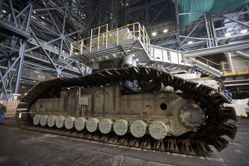
Executive Summary
In October 2017, the Human Exploration and Operations Mission Directorate (HEOMD)
Knowledge Capture & Transfer (KCT) team conducted video interviews with element managers in
the Exploration Ground Systems (EGS) Program Office at Kennedy Space Center (KSC). The
immediate goal was to capture a point-in-time profile of challenges, solutions, and lessons learned
derived from EGS element development activity from the end of the Space Shuttle Program (SSP)
to the present time. The ultimate objective is to transfer this knowledge to other program and
project managers and participants across NASA to enhance effectiveness and efficiencies in
implementing their activities.
This report summarizes key observations from the interviews and is complemented by nine video
interviews located on the “Knowledge @ NASA” YouTube Channel. This activity represents a
collaboration between HEOMD, the Exploration Systems Division (ESD) Strategic
Communications Office, the Agency Chief Knowledge Officer (CKO), and the KSC-based EGS
Program Office.
Interviews were conducted with element managers from the following projects:
   •   Vertical Assembly Building (VAB)               •   Landing and Recovery
   •   Crawler-Transporter (CT)                       •   Launch Pad 39B
   •   Logistics                                      •   Thermal Protection System
   •   Launch Equipment Test Facility                     Facility (TPSF)
       (LETF)                                         •   Mobile Launcher (ML)
   •   Launch Control Center (LCC)
Key Management Success Factors:
   •   Co-location: Several managers identified co-location of the civil servant and contractor
       teams as critical in addressing communication issues that impeded progress. Co-location
       enabled frequent face-to-face communication—facilitating rapid resolution of technical
       issues and promoting collaboration.
   •   Communication: Managers in every case emphasized the importance of communicating and
       enabling communication vertically and horizontally within the project team. All modalities
       of communication were recognized as important—especially face-to-face.
   •   People: The interviewees universally cited the outstanding skill, dedication, and excellence
       of their workforce and the need for managers to nurture, support, train, and enable their
       staff. Also discussed was the need for managers to recognize and consider employees’
       family/life issues and obligations.
   •   Organization: Streamlining their organization structure and work processes was discussed
       as an important consideration in effectively accomplishing their mission.
   •   Procurement: Several managers cited the importance of exploring innovative procurement
       approaches to address the unique challenges of rapidly changing requirements and evolving

                                                                                                  ii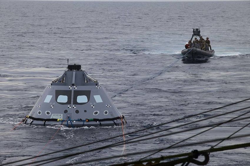
needs. The use of Undefinitized Contract Changes (UCA) was cited as an important tool in
       maintaining schedules.
   •   Design Considerations: Design-related success factors included: (1) maintaining as much
       margin as possible as a means to address future requirement changes, (2) learning from test
       failures (design, test, redesign), and (3) employment of modeling and simulation
       technology.
   •   Real-time Problem Solving: “Brute Force” is the term employed in the ML project as a way
       to address intractable problems by assembling stakeholders on-site, face-to-face to engage
       in real-time, hands-on problem resolution.
   •   Peer Review / Lessons Learned: Seeking a fresh perspective on a design or proposed
       operation was identified as an important management practice (as well as reviewing lessons
       learned and selectively engaging knowledgeable and experienced retirees) to assist in
       planning or conducting reviews.
   •   Schedule Risk Awareness: Risk management was cited most often in the context of
       schedule management. Identifying potential threats to the critical path was a universal
       concern and served as a driver for other management elements (e.g., procurement,
       organizational streamlining, co-location).
Significant Implementation Challenges:
   •   Parallel Development: the imperative to move forward while monitoring evolving
       requirements, making assumptions, and sometimes the need to re-do work.
   •   Technical Integration: managing multiple (40-plus in the case of ML) project elements and
       multiple contractor teams—ensuring flow-down of requirements and implementation of
       requirement changes as well as managing interfaces.
   •   Safety and Hazards Management: ensuring all safety risks are identified and effectively
       controlled and/or mitigated.
   •   Working with Heritage Hardware: finding 50-year-old, as-built drawings and addressing
       parts obsolescence.
   •   Schedule Management: planning and maintaining schedule in a high-change traffic
       environment.

Each of the nine interview chapters concludes with a first-person message from the interviewee to
students (in all levels of school) addressing Science, Technology, Engineering, and Mathematics
(STEM), and sharing their enthusiasm for working at NASA and the excitement and privilege of
working within the EGS organization to prepare KSC for the 21st century.

                                                                                                    iii
Contents
Executive Summary.................................................................................................................... ii

Part I. Introduction..................................................................................................................... 5

   Preparatory and On-Site Activities.......................................................................................................... 6

   Organization of Report: Themes and Framework ................................................................................... 6

   Additional Resources .............................................................................................................................. 6

Part II. Lessons Learned.............................................................................................................. 7

   (I) VAB: This Old House ........................................................................................................................... 7

   (II) Launch Pad 39B: Towers on the Hill ................................................................................................. 10

   (III) Crawler Transporter: “Still crawling after all these years” ............................................................. 13

   (IV) Launch Control Center: “We launch rockets…”............................................................................... 16

   (V) Mobile Launcher: The 400-Foot Cradle ............................................................................................ 19

   (VI) Landing and Recovery: Welcome Home ......................................................................................... 22

   (VII) LETF: Shake, Rattle, and Roll ......................................................................................................... 25

   (VIII) TPSF: “Tiles ‘R Us” ........................................................................................................................ 28

   (IX) Logistics: Space Depot .................................................................................................................... 30

   (X) Appendix A: Acronyms ………………………………………………………………………………………………………………. 33

   (XI) Appendix B: Interviewees …………………………………………………………………………………………………………. 34

                                                                                                                                                      iv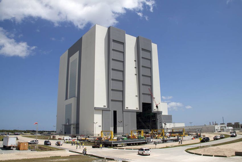
Part I. Introduction
In October 2017, the Human Exploration and Operations Mission Directorate (HEOMD)
Knowledge Capture & Transfer (KCT) team conducted video interviews with element managers
in the Exploration Ground Systems (EGS) Program Office at Kennedy Space Center (KSC). The
immediate goal was to capture a point-in-time profile of challenges, solutions, and lessons
learned derived from EGS element development activity from the end of the Space Shuttle
Program (SSP) to the present time. The ultimate objective is to transfer this knowledge to other
program and project managers and participants across NASA to enhance effectiveness and
efficiencies in implementing their activities.

This report summarizes key observations from the interviews and is complemented by nine video
interviews located on the “Knowledge @ NASA” YouTube Channel under the “Exploration
Ground Systems” Playlist. Interviews were conducted with element managers from the following
projects:

   •   Vertical Assembly Building (VAB)
                                                     •   Launch & Recovery
   •   Crawler-Transporter (CT)
                                                     •   Launch Pad 39B
   •   Logistics
                                                     •   Thermal Protection System
   •   Launch Equipment Test Facility
                                                         Facility (TPSF)
       (LETF)
                                                     •   Mobile Launcher (ML)
   •   Launch Control Center (LCC)

                                                                                               5
Preparatory and On-Site Activities
Preparatory telephone interviews were conducted with each participant during mid to late
September 2017. Discussions addressed goals, objectives, and a preliminary interview outline
which participants were asked to tailor in advance of the on-site video sessions. After a delay and
rescheduling associated with Hurricane Irma, the KCT team arrived on-site October 9th.
Interviews were conducted on the afternoon of October 10th and all day on October 11th and 12th.
A demonstration with video capture was conducted at the Thermal Protection System Facility
(TPSF) on October 13th.

   •   Tuesday: Vehicle Assembly Building, Crawler-Transporter, Logistics
   •   Wednesday: Launch Equipment Test Facility, Launch Control Center, Launch &
       Recovery, Launch Pad 39B, Thermal Protection System Facility, Mobile Launcher
   •   Thursday: TPSF Demonstrations

Organization of Report: Themes and Framework
This report is organized by EGS element. Within each element chapter the following format is
employed:
1. Element Functions and Interfaces
2. Renovations and New Features
3. Design, Development, Test & Evaluation (DDT&E) Challenges / Solutions
4. Project Management Success Factors
5. Thoughts for NASA’s Next Generation (STEM-related message presented in first-person
narrative)

Additional Resources

KSC EGS Web-based Module: This report has companion video content deployed on the
NASA YouTube Channel: https://www.youtube.com/knowledgenasa

                                                                                                 6
Part II. Lessons Learned
(I) VAB: This Old House
(based on a video interview with Jose Perez-Morales)
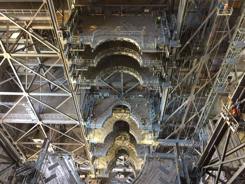
1. Element Functions and Interfaces
The iconic Vehicle Assembly
Building, or VAB, is one of the most
visible landmarks at KSC. The VAB
is 525 feet tall and is one of the
largest buildings in the world by
volume. The VAB is divided into
four high bays linked by a transfer
aisle.
The VAB is where the launch
vehicle and spacecraft are stacked
atop the ML support structure,
integrated, and prepared for rollout
to the launch pad on the CT. Figure 1: Vehicle Assembly Building at Kennedy Space Center
An overarching objective of EGS
has been to do more of the integration and preparation work inside the VAB as opposed to on
Pad 39B exposed to environmental elements. It is noteworthy that this is a return to the approach
employed during the Apollo program. The shift in approach will enable completion of most
integration activities in the protected VAB environment and allow the management team to
select the right weather for rollout and final integration on the pad.
2. Renovations and New Features
Renovations in work are focused on High Bay 3 to enable and support the assembly and
processing of the Space Launch System (SLS) vehicle on top of the ML. The VAB team
completed a three-year project installing 20 new work platforms and conducted verification
testing prior to the planned ML arrival at High Bay 3 in May 2018. The 20 new state-of-the-art
platforms can be reconfigured for any launch vehicle, not only the SLS. Each platform not only
can be moved up or down 10 feet, but also has an insert that can be modified to conform to any
vehicle shape. Each platform provides a host of “commodities” and support functionality,
including electrical power and pneumatics (GN2, Helium, and compressed air).
7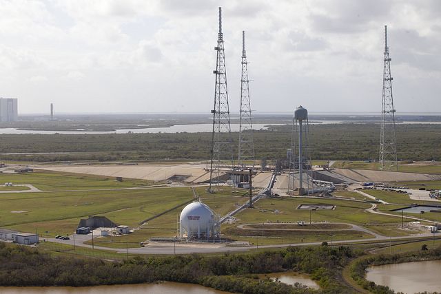
3. DDT&E Lessons Learned / Challenges and Solutions
Unanticipated Flexing: One of the biggest surprises the project encountered was the inability to
install the first platform because of misalignment of mounting hardware. The platforms were
designed with holes drilled to match
corresponding holes on the supporting
VAB structure. The four pins that
should have fit perfectly were
problematic, taking hours to finally
insert. What was the problem? A
dynamic structural response model
revealed that while suspended by the
crane lowering it into position, the
platform was flexing—up to two
degrees. This flex or rotation was
enough to create a critical
misalignment. Solution: the team
installed two, 70-foot stiffener beams Figure 2: Platforms at VAB
under each platform, eliminating the
dynamic flex in the platform. Subsequent platforms were successfully installed in under 10
minutes.
Design for Fabrication: “Design is fine, but how are you going to fabricate that design?” Perez-
Morales noted the ongoing challenges associated with implementing designs that did not
consider the difficulties involved in fabrication. Program and project managers should consider
design for manufacturability, or DFM, as an important consideration in overall design tradeoffs.
4. Project Management Success Factors
Co-location: One of the first actions undertaken by Perez-Morales when he moved over from
Pad 39B project to become VAB element manager was to consolidate the workforce. He moved
employees—previously scattered in various locations with some far away from the work taking
place—into a central location near the VAB and close to the prime construction contractor.
Perez-Morales remarked, “That alone solved a lot of the issues we had.” The improved face-to-
face interaction solved most of communication issues and facilitated rapid resolution of issues
that previously might have lingered unresolved for weeks.
People: Perez-Morales commented, “I have the most qualified team of people working for me.”
He further noted, “If you surround yourself with the right people with the right attitude—no
matter what the challenge, you will be successful.”
Design Considerations: During the design process, it is critical [important] to consider
challenges to fabrication of the design.

                                                                                                  8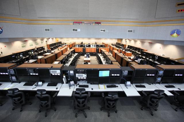
Broad Perspective: To be successful, project managers need to maintain a broad perspective.
“Understand the environment, see the big picture, and don’t drown in the details,” said Perez-
Morales.
5. Thoughts for NASA’s Next Generation (STEM-related message)
At NASA, every job or project is a challenging one. You work with some of the most qualified
and amazing people in the space industry, working on things that are out of this world. If you are
interested in the space program, get involved with the various NASA programs because we will
need all kinds of professionals in the future. Stay in school and obtain a higher education.

                                                                                                 9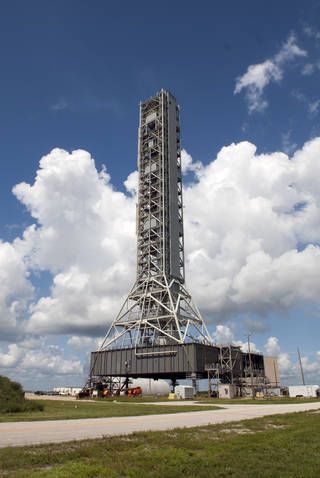
(II) Launch Pad 39B: Towers on the Hill
(based on a video interview with Regina Spellman)

1. Element Functions and Interfaces
The EGS Pad 39B element is
overseeing upgrades to Launch
Pad 39B and other supporting
facilities to support NASA’s deep-
space missions, SLS, and Orion as
well as the transition to a multi-
user spaceport. The Pad 39B
element provides not only the
structural foundation, but all the
supporting systems to supply the
ML and the vehicle. As shown in
the adjacent photo three lightning
protection system (LPS) towers          Figure 3: Launch Pad 39B at KSC
have been constructed, each
reaching 600 feet. This design will protect any vehicle that can leave the VAB. Pad B provides
up to 900,000 gallons of both LH2 and LO2, enough to support multiple SLS launch attempts.
The complex perimeter is approximately two miles. The water tower supporting the ignition
over-pressure sound suppression system holds 400,000 gallons of water and empties in less than
30 seconds. Pad 39B manager Regina Spellman characterizes the pad as an “RV park.” She
remarked, “We provide all the facility systems, commodities, instrumentation, communications.
If the Mobile Launcher can’t carry it, we provide it.”
Also of note, the pad isn’t sitting on a hill. It is a man-made structure built up from the ground
approximately 50 feet. Underneath the surface are catacombs and rooms packed with wire
bundles, instrumentation, and mechanical systems.

2. Renovations and New Features
Spellman summarized, “Since taking over Pad 39B from the SSP we have renovated, repaired,
replaced, or removed almost every system out there.” Pad modification began in 2007 while the
space shuttle was still flying off Pad 39A. Work continued through the Constellation Program,
pausing to enable launch support for the Ares I-X test flight.
In implementing the “clean pad” concept, some of the first systems removed were the venerable
space shuttle fixed and rotating service structures that provided support for month-long
processing campaigns prior to launch. The clean pad concept emphasizes minimizing the time on
the pad with the lion’s share of processing carried out in the VAB or other facilities.

                                                                                                10
Spellman described the work on Pad 39B as a jar with a number of big rocks (major tasks) and
the gaps filled with innumerable smaller rocks (smaller tasks). The big rocks included the
following:
• 600-foot lightning protection towers, sized for any vehicle that could roll out from the VAB
• Cables everywhere—over 300 miles of copper cable removed and replaced with fiber optic
• Flame deflector
• Flame trench
• Environmental control system (HVAC on steroids)
• Air, GN2 purge
• New communication system
• Replacement of water system piping in the pad perimeter
• Installation of new ignition overpressure/sound suppression bypass valves at the valve
complex
3. DDT&E Lessons Learned / Challenges – Solutions
Parallel Development: One of the biggest challenges encountered was the need to work in
parallel with the SLS launch vehicle development. The parallel schedules require constant cross-
program communication to ensure the vehicle design changes and evolutions can be
accommodated by designs of the supporting Pad 39B infrastructure. In some cases, it is and has
been necessary to make assumptions based on the best available information and past experience.
In some cases, rework may be necessary. While parallel development may not be the most
efficient approach, it can be successfully implemented with constant communication and
conservative assumptions when necessary to keep work moving forward.
Task Phasing: A unique challenge for the pad work was the constraint of having to do projects
in serial fashion due to their physical size. “It’s been like putting large rocks in a jar. You can
only do one at a time, and you fill all the gaps with the little rocks,” she said. The challenge was
to phase large construction jobs in the right sequence while getting all the smaller jobs done in
parallel.
4. Project Management Success Factors
Spellman eloquently focused on the importance of people in the process and the art of
successfully managing people. “The technical challenges aren’t your biggest problem. Those are
the fun ones,” she said. “It’s the people challenges that you have to work hard at. You can never
communicate enough, and don’t forget—people are human.”
Specific workforce issues include:
Communication: Effective communication is critical for successful projects. Communication is
often a potential failure mode when people begin to rely on one-way communication (e.g., I sent
you an email …?). What is needed is affirmation in communication—either face-to-face or over
the telephone.
11Human Needs: Sensitivity to individual feelings and emotions and recognition that workers
have lives outside of work is an important concept for successful managers.
Thoughtful Resolution of Conflicts: It is not unusual for well-motivated team members to
differ on the approach to solving a problem. Conflicts need to be resolved with considerate
evaluation of differing opinions and a decision made based on whatever is best for the project.
Workforce Direction: People need direction. The lack of decisions on key issues is divisive and
degrades morale and, ultimately, teamwork. Unresolved or lingering issues soon become critical
path items on the integrated schedule.
People Make Mistakes: People are people—and people make mistakes. What is important is
how you handle those mistakes when you are the manager. Spellman said questions to ask are:
“How can we recover? How we can avoid future mistakes like this? How can our process be
improved to mitigate a reoccurrence? What are the lessons learned? Who do we need to share
these lessons learned with?”
5. Thoughts for NASA’s Next Generation (STEM-related message)
At NASA, we are creating history. We are making a legacy for future generations. We also get to
work on very unique and challenging problems every day. Believe in yourself. We don’t say,
“The sky’s the limit at NASA,” because there are no limits for us, and there’s no limit for you,
either.
12(III) Crawler Transporter: “Still crawling after all these years”
(based on a video interview with John Giles)
1. Element Functions and Interfaces
The CT will carry NASA’s SLS and Orion spacecraft to Launch Pad 39B for launch on
Exploration Mission-1. The crawler-transporters were constructed in the mid-1960s to move the
Apollo Saturn V rockets that took
American astronauts to the moon, Skylab
and Apollo-Soyuz Test Project. Through
three decades of space shuttle flights, the
crawlers served in the same role until the
final space shuttle mission in 2011.
Crawler transporters are designed to lift
the mobile launchers with launch vehicles
mounted atop, then move the entire
integrated stack from the VAB to the
launch pad. The crawler transporter,
designed in the early 1960s, weighs over
Figure 4: Crawler Transporter
6 million pounds, is as large as a major
league infield (90 feet by 90 feet), and
has more than 400 shoes, each one weighing over a ton.
The CT, described by John Giles as “a hands-on piece of equipment,” is an engineering marvel
requiring support from multiple disciplines, including structural, electrical, and mechanical. The
CT has an interesting design heritage with elements derived from heavy mining equipment and
diesel-electric locomotives. The prime mover power source is an American Locomotive
Company (Alco) V16, 2750 HP diesel electric generator that powers the CT 16 traction motors.
While 53 years old, the engine is still considered “low mileage” with the odometer at only 2,100
miles. Electrical power (alternating current) is provided to the CT, mobile launcher, Mini
Portable Purge Units (MPPU) and launch vehicle by a new twin turbo-charged Cummins diesel
engine.
The optimum operational scenario is a roll to the pad in the early morning hours (avoiding
inclement weather) cruising at a top speed of 0.8 – 0.9 mph. The six-to-seven-hour trip is
carefully managed by a team of 20 engineers and technicians who are continually monitoring
performance metrics (level, strain, pressure, weight, lubrication levels, temperatures, and
vibration) as well as pre-programmed redlines and alerts.
2. Renovations and New Features
The heaviest SLS rollout weight, including the mobile launcher, is estimated to be about 18
million pounds. That compares to the Apollo Saturn V and space shuttle rollout weight of
approximately 12.3 million pounds. The challenge has been to analyze and redesign the entire
13load path from the crawlerway river rocks to the drive train to the support “trucks” to handle the
net increase of 6 million pounds. Major changes include:
• New bearings (each weighing one ton)
• New jacking equalization and leveling (JEL) hydraulic cylinders
• New rebuilt gearboxes
• New engine (Cummins replacing the previous White diesel)
• New brakes
• New shear webs (adding structural steel inside each truck)
In addition, evaluations are underway to assess the capability of the crawlerway to ensure the
river stone top layer and supporting layers of rock and limestone can bear the increased load. A
final area under evaluation is the capability of the Cummins generator to provide increased
power output for ground support equipment serving the ML and SLS during the roll to the pad.
3. DDT&E Lessons Learned / Challenges - Solutions
Design Drawings: The CT design drawings were created by engineers using mechanical pencils
and velum over 50 years ago. The CT team worked with engineers at Ames Research Center
(ARC) to carefully review and update the drawings as necessary to reflect the as-built
configuration. ARC provided the principal structural analysis support for the modifications based
on the updated design documents.
Crane –Workflow Modeling: The KSC weather environment has always posed risks to
schedule. Outside work is subject to severe weather, high winds, rain, and corrosion of unpainted
ferrous materials. Not surprisingly, the CT project was motivated to perform the work in the
VAB avoiding complications of bad weather. The CT project involves very heavy components
that require one crane—and often two—to perform necessary lifts. The question was, “Will the
VAB cranes (permanent and mobile) be able to perform the complex maneuvers required to
implement the modifications?” Boeing’s Design Visualization team’s VAB crane and lifting
device computer simulation model was enlisted to assess the feasibility of CT refurbishment in
the VAB. The model demonstrated that all of the moves and lifts could be accomplished and the
plan went forward successfully.
3D Printing to the Rescue: The CT has miles of piping and tubing that interfaces with valves.
The installation of these systems was being set back because of delays in the manufacturing and
delivery of the specialized valves. The CT project avoided this schedule bottleneck by using
KSC’s 3D printing capability to create highly accurate plastic models of the actual valves,
including threads, to enable work crews to move forward with installation of piping while
waiting for the real valves to arrive.
Measurements and Grease: How did KSC maintain the CT so well for 50 years? First: “Pump
grease everywhere.” Second: “We measure everything we can,” including temperatures,
pressures, vibrations on every motor and pump, and power consumed, and also maximize the use
of photography. The CT maintainability story is noteworthy indeed.
144. Project Management Success Factors
Amazing Team: The importance of teamwork and the stability of the team composition was
highlighted as a very real success factor in the implementation of CT upgrades. It was noted that
the same team served from beginning to the end and that corporate knowledge was maintained
and accomplished by pairing older, more experienced workers with younger engineers in hands-
on implementation of critical functions. In addition, the on-site CT team was augmented by the
design engineers at ARC and reach back to a cadre of retired CT experts who had spent careers
working with the CT.
Communication: Giles, the CT project manager, is “on the floor every day” communicating
with work teams, observing progress, and discussing issues. This level of engagement is deemed
a critical ingredient in fostering teamwork.
Overdesign: One way to accommodate anticipated design changes is to overdesign. This option
is not always available, especially in weight critical systems (launch vehicle or spacecraft) but is
certainly a viable option for ground support equipment and ground support infrastructure.
5. Thoughts for NASA’s Next Generation (STEM-related message)
Beyond the more obvious need to take classes in math, science, or engineering, Giles noted the
importance of continuous learning as a mental framework, with suggestions to follow your
interests and “keep on learning.”
15(IV) Launch Control Center: “We launch rockets…”
(based on a video interview with Steve Cox)
1. Element Functions and Interfaces
"We launch rockets … That's what we're preparing to do here," summarized Steve Cox, element
manager for the EGS LCC,
in a recent interview. The
LCC is comprised of four
firing rooms. Firing Room
1, also called the Young-
Crippen Firing Room, has
been completely renovated
and will serve as NASA's
firing room for launches of
the SLS and Orion
spacecraft on exploration
missions beginning in 2017.
Firing Room 2 (FR2) serves
as the principal command
and control software verification and validation facility. FR2 will also provide customers
flexibility for checkout, training, launch and post-launch evaluation needs. Firing Room 3 has
been configured as a development area for Launch Control System software development
applications, and models and simulations. FR3 also contains the Customer Avionics Interface
Development and Analysis (CAIDA) emulator of Orion's flight software and hardware. CAIDA
will be used to support EGS Orion testing and development. Firing Room 4 serves as a highly
reconfigurable, multi-user facility with the capability of supporting other NASA customers, other
government customers, or commercial launch providers. Each room can be configured as needed
to meet a user's particular requirements. Customers would bring in their own systems and
equipment. FR4 is divided into four smaller control rooms designed to support smaller missions
that may only require 25 to 30 people for a test. As customers' needs grow and they get closer to
launch, adjoining rooms can be opened to accommodate an increased crew size of 50 to 100.
2. Renovations and New Features
Beneath the carpeted, raised floors of the LCC, the team found “50 years of wiring”—
sedimentary layers (sometimes 18-inches thick) corresponding to programs reaching back to the
Apollo era. The team removed over 100, 4-foot-by-4-foot pallet bins full of cut wiring and old
equipment. They also removed outdated plumbing and electrical service wiring and fixtures as
well as anything identified and documented in drawings as “not to print.” Once cabling was
removed the base concrete floor was resealed, and the team was prepared to rebuild from the
concrete up. New, raised floors were installed. Fiber optic cabling was installed, vastly
16increasing bandwidth while using a fraction of the available space. Windows and doors in the
LCC were replaced and shutters were removed. Old wiring was also removed from the maze of
distribution pipes running from the basement of the LCC to other processing and launch facilities
(e.g., VAB, Pad 39B, OPF) and replaced with fiber optic cabling. New energy-efficient LED
lighting was added throughout the firing room. New sound-absorbing ceiling tiles were installed
to provide privacy and reduce noise levels. The only elements that remain in FR-1 are the shuttle
and Apollo launch plaques on the Firing Room walls.
3. DDT&E Lessons Learned / Challenges – Solutions
Historical Recordation: One challenge confronting the team was an initiative to preserve
historic Firing Room 2 as a monument to the Apollo program. The team worked with historic
preservation officials to forge a compromise. Certain artifacts (plaques and launch readiness
status board) were left in place and an extensive video documentation effort was undertaken to
digitally preserve the room prior to the initiation of renovation activities. For more information
on the renovations to the LCC and how it was preserved, click on this link:
https://environmental.ksc.nasa.gov/EnvironmentalPlanning/CulturalResources/LCC
4. Project Management Success Factors
Four-Way Teeter-Totter: Imagine a
four-way teeter totter balancing on a post.
The project manager lives at that junction
and is challenged to maintain a balance
between the four arms: (1) design/build
activities, (2) operational requirements,
(3) resources, including budget, people,
and equipment, and (4) schedule. The
manager is making risk-balancing
decisions that respond to external
forces—principally changes in
requirements. The interplay between the
changing operational requirements and Figure 5: The Four-Way Teeter-Totter balances requirements, costs,
the design/build team is most critical and schedules, and technical performance
warrants constant communication. The
classic project management failure mode is “requirements creep,” simply absorbing requirement
changes without increases in budget and schedule. The four-way teeter totter reinforces proactive
management action to balance the risk between the various domains— absorbing schedule hits or
re-baselining, pushing back on certain requirements, finding alternative designs, or going after
more resources.
Innovation: Give smart young people the freedom to solve problems within the given resources,
budget and schedule. What they lack is experience. The key to innovation and maintaining
17motivation is to blend old and new to create teams comprised of younger and more energetic
hires with older and more experienced employees.
Critical Path Emphasis: A key approach for balancing the four-way teeter totter discussed
above is to keep an eye on what’s on the critical path. Put another way, actively managing the
critical path reduces project risk and leads to overall program success.
Peer Review: Whenever possible bring in a fresh set of eyes to evaluate designs or planning
products, and embrace independent evaluation.
Fun: As a manager, make sure everyone is having fun! If the team is having fun, you will get
their best efforts. If they like what they are doing and you can’t make them go home—they will
do great things for you.
5. Thoughts for NASA’s Next Generation (STEM-related message)
The most important tool is yourself. Invest in yourself. Find something you are interested in and
learn all about it. When you go to work, speak up. Don’t sit back. Have an opinion.
18(V) Mobile Launcher: The 400-Foot Cradle
(based on a video interview with Cliff Lanham)
1. Element Functions and Interfaces
The ML is the tower-like structure that serves as a
cradle for the launch vehicle during stacking at the
VAB, transport to Pad 39B, and launch. The ML
weighs 10.5 million pounds and is 400 feet tall with
662 steps required to climb from the deck to the top.
The ML is also host to multiple deployable T-0
umbilical arms that are attached to the launch vehicle
during processing in the VAB. At the moment of
launch (T-zero), the umbilicals are disconnected and
retracted. The umbilicals are designed to provide the
services and commodities necessary for safe and
efficient stacking and integration of the SLS and
Orion, including pneumatics, electrical power,
communications, and environmental control purges.
After stacking, test, and checkout (leak checks, data
checks, and electrical checks) in the VAB, the ML and Figure 6: Mobile Launcher
launch vehicle travel atop the crawler transporter to
Pad 39B for final tests, checkout, and launch.
2. Renovations and New Feature
The ML was originally built for the
Constellation Program Ares I launch
vehicle, a “single stick” design that
required only a single, central flame
hole for the rocket exhaust. The much
larger SLS requires the central, core
stage flame hole, but also flanking
flame holes for the twin solid rocket
boosters. This required a major
modification effort during which 750
tons of steel were removed and over
1,000 tons added.
Figure 7: Mobile Launcher Design
Another major effort was undertaken
to install the ground support equipment (GSE) necessary to assemble, process, and launch the
SLS rocket and Orion spacecraft. The scope of work included the installation of mechanical,
19electrical, and fluid subsystems. The effort included installation of more than 800 mechanical,
fluid, and electrical panels; about 300,000-plus feet of cabling; and miles of tubing and piping.
As discussed above the ML has been outfitted with multiple umbilical arms, each a highly
complex project managed by a dedicated project team and manager. The list of umbilicals in
development for the SLS/Orion space system include:
• Crew access arm
• Orion service module umbilical (260-foot level)
• Interim cryogenic propulsion stage (ICPS) umbilical
• Core stage forward skirt umbilical
• Vehicle stabilizer (260-foot level)
• Core stage inter-tank umbilical
• Tail service mast umbilicals for liquid hydrogen and liquid oxygen fueling (on the deck)
3. DDT&E Lessons Learned / Challenges – Solutions
Requirements Flow-down & Technical Integration: Probably the biggest challenge (ongoing)
is the technical integration of over 40 individual project teams. The challenge is further
complicated by the need to coordinate and communicate across three separate design contracts:
subsystem design, structural design, and GSE design and installation.
The mitigation approach has included co-location with construction contractors, daily meetings,
and the establishment of a technical integrator on every project team.
Changing Requirements: As Cliff Lanham noted, “Proceeding with an incomplete design into
construction…creates significant change traffic.” Change is inevitable in a complex project with
so many sub-projects, ongoing umbilical testing in the LETF, multiple design contractors, and
the parallel development of SLS and Orion. Most of these requirement changes require contract
changes. Standard contract change processes proved too cumbersome to support the work
environment. The mitigation approach has been to work with contract officials to employ a
procurement process called undefinitized contract action, or UCA. This process has accelerated
the project’s ability to meet the landscape of changing requirements.
Overly Tight Construction Specifications: Designers need to recognize that they are designing
for steel construction with construction tolerances. Over specification (0.1 inch where 1 inch
would be more appropriate) drives cost and creates delays in reconciling what is really required.
Single Supplier Specifications: Designers can also impede the build process by specifying
material available from only a single supplier. This drives cost and often involves long lead times
that impact schedule.
204. Project Management Success Factors
Co-location: A key success factor has been co-location with construction contractors that
enables real-time problem solving (discussed further below).
Communication: Daily meetings, dedicated technical integration managers, and staying plugged
in to activities (e.g., LETF umbilical testing) that may lead to requirement changes have
contributed to success.
Relationships: Maintaining a close-knit team has been a key success factor. This includes both
civil servants and contractors. Relationships build the trust necessary to solve problems and keep
moving forward.
Brute Force: “Brute force” is the phrase employed on the project for real-time problem solving
that takes place face-to-face in the field with hardware in hand—typically dealing with structural
interferences. The goal is to quickly resolve the issue, make the hardware work, and move
forward.
UCA: The use of UCA, an “out-of-the-box” procurement technique, was a major assistance in a
change-heavy project like ML.
Note: The NASA Federal Acquisition Regulation Supplement (1843.7001) defines an Undefinitized
contract action (UCA) as a unilateral or bilateral contract modification, or a delivery/task order in
which the final price or estimated cost and fee have not been negotiated and mutually agreed to by
NASA and the contractor. For purposes of tracking definitization schedules of UCAs, letter
contracts are considered to be UCAs and will be tracked as such by the Program Operations
Division within the Office of Procurement. Otherwise, the specific requirements, policies, and
procedures for letter contracts are in FAR 16.603 and NFS 1816.603.
5. Thoughts for NASA’s Next Generation (STEM-related message)
We are at the advent of a 30-year journey to Mars. You will inherit this program, and we need
you to carry it into the future. Many will tell you, “Study hard, take math and science classes,
and go to college.” I agree with that, but I have another recommendation to add to the list.
Become a “tinkerer” at home. Take things apart, build stuff, learn about electricity, do science
experiments, and participate in a science fair. Something you learn as a “tinkerer” may come
back to serve you years in the future.
21(VI) Landing and Recovery: Welcome Home
(based on a video interview with Melissa Jones)
1. Element Functions and Interfaces
The Landing and Recovery
Project is responsible for the
recovery, retrieval, and rescue of
the Orion spacecraft. Recovery
refers to a nominal (planned)
recovery of the crewed Orion off
the coast of San Diego. The
requirement is to be able to open
the crew door within two hours
after splashdown. Retrieval refers
to recovery of an uncrewed
capsule at an unplanned landing Figure 8: Spacecraft Recovery Test
site. Rescue refers to recovery of
the flight crew after an abort in the Atlantic or Indian Ocean.
The nominal recovery sequence of the Orion will involve landing in the Pacific Ocean off the
coast of San Diego; approach of the recovery ship, a U.S. Navy Landing Platform Dock (LPD)
Class 17 amphibious ship; and evaluation and safety sweep of the recovery area for debris or
toxic chemicals. Over 20 to 30 pieces of debris are jettisoned from the capsule. The debris to be
recovered includes the three main parachutes and the forward bay cover.
When astronauts come back from the microgravity environment they experience some form of
de-conditioning, which is the effect that space has on their body. The team is currently working
on two recovery systems that will allow astronauts to egress the capsule and access medical
attention as fast as possible. One will allow recovery in the open water and one will enable
recovery in the well deck of the ship.
For open water recovery of the flight crew, a stabilization collar is attached to the capsule and
inflated. This serves to make the capsule more stable in the open ocean and also provides a
platform for the DoD to stand on while they are removing the crew. The crew is then transported
to the ship via small boats or helicopters.
Well deck crew recovery involves the crew staying in the capsule until it is in the recovery cradle
in the ship. Once the area is secured the recovery ship makes a close approach to the capsule, and
the Navy divers attach the winch and tending lines to the capsule. The capsule is pulled into the
flooded well deck and positioned over the cradle. Once the capsule is positioned in the cradle,
the stern gate of the ship is closed, and the well deck dried. The methods allow the flexibility for
crew egress at several points along the recovery timeline.
22Once the ship returns to port in San Diego, the Orion capsule will be secured onto a trailer and
outfitted with ride monitoring instrumentation for the trip east. Throughout the recovery process,
the team will carefully ensure that the heat shield does not get damaged, enabling a
comprehensive post-flight performance evaluation.
Abort retrieval or rescue missions in the Atlantic will involve KSC-based helicopters with a 200-
mile range that will deploy divers and render assistance as needed until a crane ship with a
hoisting sling arrives. If the landing occurs outside the helicopter range, a C-17 aircraft will be
deployed to render assistance prior to the arrival of a crane ship. Abort retrieval or rescue
missions in the Indian Ocean (a very low likelihood) will depend on ships of opportunity. Orion
is designed to sustain the crew afloat for a minimum of 24 hours.
2. Renovations and New Features
Redesign: The team learned that they had underestimated the loads that hardware such as lines,
and crew module (CM) attach points would see during testing and recovery. No one had ever had
a capsule in the well deck of a Navy ship. Once the well deck was flooded, the CM started
surfing on the top of waves like a surfboard, and the more it moved, the harder it was to control.
The hardware was clearly under-designed. With a better understanding of the operational
environment, lines and attach hardware were strengthened. The team also deployed
instrumentation to monitor the loads during subsequent testing.
LLAMA: After the failure, early Lead Design Engineer Jeremy Parr developed an active
recovery method called the Line Load Attenuating Mechanism Assembly (LLAMA). The
LLAMA design helps the Navy line handlers to safely maintain high tension in the tending lines
during recovery of Orion into the well deck of a ship. It also regulates the amount of tension in
the lines to ensure equal loading on the vehicle. The LLAMAs are mounted on the ship’s T-bits,
and the mechanisms provide all tending line control of the crew module once it enters the well
deck and until it is secured on the recovery cradle pads. It’s unique because it basically acts like
a giant fishing reel. It allows sailors to safely pull slack out of the lines while pressure is holding
a car braking system at a predetermined pressure. If the force of the line-pulling exceeds the
pressure, then the LLAMA allows the line to “pay out” instead of breaking, just like a fishing
reel does.
3. DDT&E Lessons Learned / Challenges – Solutions
Learning from Test Failures: In 2014, NASA and the Navy conducted an underway recovery
test (URT-1) in preparation for the EFT-1 mission. That test exposed some significant issues
with the recovery process. First, the 20,000-pound Orion simulator test article was very difficult
to control and careened around the well deck in the turbulent standing waves. Several lines
snapped due to the jerk loads and sailors manning the ropes suffered rope burns and, in one case,
a broken finger. This failure stimulated an extensive trade study to evaluate alternative methods
and processes for recovery that ranged from the baseline well deck concept to submarines. In the
end, given the host of requirements beyond physical recovery (e.g., medical staff and facilities),
23the well deck concept was retained. A total of five additional tests are scheduled prior to the
2019 EM-1 flight. Underway Recovery Test-6 (URT-6) was conducted successfully as a joint
NASA/U.S. Navy exercise off the coast of San Diego in January 2018.
Safety: The recovery process design has been very mindful of potential safety hazards to the
recovery crew as well as the Orion crew. The team has identified principal hazards and is
implementing measures to mitigate potential impacts. Hazards include unexpended pyros (used
in deploying parachutes), toxic chemicals (ammonia and hydrazine), pressure vessels (high-
pressure helium), and RF energy (beacon transmission antenna). Mitigations include powering
down the beacon transmitter, deploying sensor systems for toxins in the well deck and on diver
vests, and wearing personal protective equipment. Prior to cross-country transport, the Orion
helium tank will be depressurized.
Organizational Complexity: Another challenge for the landing and recovery team has been the
inherent complexity of working with another agency with different management structures. In
this case, the U.S. Navy is providing critical support functions and personnel, including weather
monitoring, medical, boat drivers, divers, and helicopters. While the support has been stellar and
relationships have been the best, there have been challenges communicating during testing.
Test Planning, Scheduling, and Coordination: A large ship is required in order accomplish the
integrated testing to verify and validate hardware and recovery processes. Between NASA and
DoD, this requires about 600 people. Coordination with Navy and scheduling availability of the
ship and crew requires at least 15 months lead time.
4. Project Management Success Factors
Teamwork: Team is number one. The people and teamwork carry the project forward.
Lessons Learned: The team leveraged the expertise of retired NASA recovery director (James)
Mitt Heflin, who has shared lessons learned from both the shuttle program and Apollo.
Training: Extensive training of divers and recovery crews has been ongoing. Training has
included Navy personnel working with an Orion test article in the Neutral Buoyancy Laboratory
(NBL) at Johnson Space Center (JSC).
Simulation: Both testing and design activities are informed by simulation and modeling support.
Test: Testing has been the key to finding problems and implementing redesigns and process
improvements.
5. Thoughts for NASA’s Next Generation (STEM-related message)
We do things that no one else gets to do. NASA is about more than science and technology. We
have accountants, lawyers, doctors—we even have a SWAT team. No one knows what they want
to be at 18 [years old]. Try new things. Shadow people. Adults love talking about their work. Do
research. My favorite quote: “Aim for the moon because if you should happen to miss, you’ll
still be among the stars.”
24(VII) LETF: Shake, Rattle, and Roll
(based on a video interview with Jeremy Parsons)
1. Element Functions and Interfaces
The LETF is where functional tests are conducted for the structural arms and umbilicals that
connect SLS and Orion with the mobile launcher. Some of these umbilicals are massive—two
stories high and weighing 65,000 pounds. Aptly named, umbilicals are the launch system life
lines providing pneumatic and
environmental air commodities,
electrical power, telemetry, and
communications. Several also flow
extremely hazardous cryogenics (LH2
and LO2). Besides providing essential
services, the arms are also required to be
agile and nimble, disconnecting at T-
zero (launch ignition) and then
retracting or swinging out of the way.
Each umbilical has a primary and Figure 9: Umbilical Testing at LETF
secondary disconnect retraction
mechanism and is designed with high reliability components. Failure to disconnect or retract
would likely result in catastrophic consequences. They must work. Accordingly, the testing in
the LETF must be as rigorous as possible.
The unique capability and key function the LETF provides is its ability to simulate the SLS
operational launch environment, a notion central to NASA’s Test Like You Fly (TLYF)
philosophy. The LETF is equipped with two Vehicle Motion Simulators which simulate
movements of the SLS on the ML and during the first few seconds of liftoff. They have a full six
degrees of freedom. Tests are dramatic and dangerous, requiring great emphasis on safety.
Imagine a 45-foot-long, two-story, 65,000-pound structure flowing liquid hydrogen,
disconnecting and rotating 90 degrees in 3 seconds while subject to an ignition/liftoff shock and
vibration environment.
Any specific test activity is documented in a Test Requirements Document. A given verification
campaign will include multiple tests under nominal conditions as well as multiple tests with one
or more failure conditions, thus exercising and verifying the fidelity of the backup functionality.
In many situations, a test campaign may include 50 to 60 tests in the simulated launch
environment. Testing data is extensive, including sensors, video, and photogrammetry that are all
used to verify and validate the fidelity of the system being tested.
Beyond SLS and Orion (principal customers), and consistent with the multi-user spaceport
concept, the LETF is seeking to support multiple customers and is currently working with
SpaceX to host future testing activity.
25The LETF has been testing two shifts per day/six days per week/10 hours per shift for the last
year. It also has delivered 17 of 21 SLS launch accessories. The LETF is on pace to deliver three
of the remaining accessories by spring 2018.
2. Renovations and New Features
Not covered in the video interview
3. DDT&E Lessons Learned / Challenges – Solutions
Test Non-Conformances: System-level tests are designed to expose latent defects in design,
fabrication, assembly, integration, or operational procedures. The LETF certainly exposed a wide
range of issues in every test, logging over 80 nonconformances per test campaign. The results
served to identify quality control and subsystem/component testing inadequacies in the
development of each test article.
Schedule Issues: The other major impact of test nonconformances was on the LETF master
schedule. While statistical scheduling models consider weather delays and the need to address
nonconformances, the baseline schedule did not incorporate these and only addressed them as a
potential risk. This has led to consistent schedule slips that can be accounted for, but are not
always understood at higher levels. In addition, the magnitude of nonconformances taken was
not anticipated.
The disposition of each nonconformance took days and, in some cases, weeks. The challenge
was how to shrink the nonconformance disposition response time. The solution was to establish a
daily face-to-face meeting with the chief engineers for each subsystem or project team to discuss,
negotiate as appropriate, and resolve each nonconformance.
Hazardous Operations: It took two months to certify the LETF for hazardous operations.
During this time period a detailed system safety hazards analysis was performed identifying
hazards, failure modes, and potential control and mitigation strategies.
The mitigation and control measures implemented included extensive cryogenic safety training,
implementation of an upgraded fire suppression system, modification of all electrical outlets, and
development of emergency egress procedures. In addition, the prime support contractor was
required to provide training and certification of all personnel involved in cryogenic operations.
Finally, a former space shuttle cryogenic expert was placed on the LETF management team.
Other Programmatic Challenges:
Manufacturing delays: Issues with IDIQ vendor performance
Staffing: Personnel with the appropriate skills for testing and design were limited. This caused
the need to work longer shifts versus and weeks versus just being able to add personnel.
26Contract transition: The loss of critical skills and expertise during a major contract transition
had a huge impact on schedule and technical risk.
4. Project Management Success Factors
Risk Awareness: Ensure schedule risks are identified and managed.
Decision Making: Streamline decision making.
Team Composition: Establish a strong team composed of operations-minded individuals.
Skilled Craftsmen: Welders and machinists with amazing skills and precision.
Delegation: Empower project managers over individual test elements.
Technology: Photogrammetry, 3D printing to support testing fit check, 3D modeling, simulation
modeling.
5. Thoughts for NASA’s Next Generation (STEM-related message)
If you love space we have people of all sorts and backgrounds working on these projects. We
have welders, machinists, engineers, designers, artists, programmers, public affairs,
administrators, financial analysts, etc., all to make projects of this size come to together.
27You can also read