Lessons learnt during the seismic restraint design for the Acute Services Building at Christchurch Hospital
←
→
Page content transcription
If your browser does not render page correctly, please read the page content below
Lessons learnt during the seismic
restraint design for the Acute Services
Building at Christchurch Hospital
I.P.R. Black
Silvester Clark, Wellington.

ABSTRACT
Seismic restraint design in New Zealand for large services intense buildings is a developing field. There are
few examples of services intense Importance Level 4 buildings where fully compliant and modelled seismic
restraint designs have been completed. The Canterbury District Health Board (CDHB) newly completed
Acute Services Building (ASB) is an example of a project where a compliant, fully modelled seismic
restraint design has been completed by one consultant for all the services. This paper outlines the design
works carried out, some of the challenges encountered and how these challenges were overcome. This paper
also outlines lessons learnt from this project that can be taken forward to other projects. The intention of this
paper is to assist other seismic restraint design engineers and consultant teams. The lessons learnt on this
project are not only applicable to seismic restraint design engineers but also clients, project managers,
architects, lead structural engineers, MEH services engineers, fire engineers, acoustic engineers, and
contractors and subcontractors. For the seismic restraint design on a large Importance Level 4 building to be
successful, the design and construction teams all have a part to play. Considering the seismic restraint
requirements in a project is one key step. It is also particularly important that all the consultants in the team
understand the impact their design decisions will have on the seismic restraint design and work together to
solve the challenges.

1    INTRODUCTION
The Christchurch District Health Board (CDHB) new Acute Services Building is one of the largest,
Importance Level 4 (IL4) projects in New Zealand where the seismic restraints for all services have been
designed and fully modelled. This project involved 21,000+ seismic restraints to suspended services, the
seismic restraint design for plant and equipment, and the design of floor mounted frames in plant rooms to
support low level services. This project also included monitoring of the installation of the restraint works.
Most of the design and documentation work for this project occurred between 2016 and 2018. Installation of
seismic restraints commenced late 2018 and was mostly completed by mid-2019.

                                                   Paper 145
NZSEE 2021 Annual Conference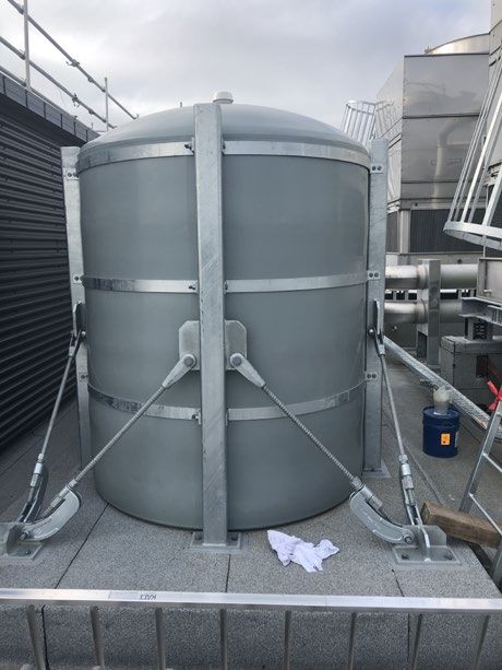
The intention of this paper is to:
1. Describe the seismic restraint design approaches used on this project.
2. Describe some of the challenges encountered and how these were overcome.
3. Discuss different approaches that could be taken on future similar projects.
4. Make recommendations for seismic restraint design approaches that can be adopted on future similar
   projects.

2    PROJECT DESCRIPTION
The construction of the superstructure for the Christchurch Acute Services Building (ASB) began in 2016
and the internal fit out was completed in 2020.
The project is made up of a ten-storey building consisting of a three-storey podium with two seven-story
towers. The structure is base-isolated, with the isolation plane located at the underside of the first storey
supported off the podium. Comfor suspended floors supported off steel beams and columns, and steel
frames provide lateral load resisting systems in both directions. The structure is designed to Importance
Level 4.
Acceleration coefficient for parts and seismic displacement were provided by the project structural engineer.

3    SCOPE OF SEISMIC RESTRAINT DESIGN AND DOCUMENTATION
The mechanical specification for this project required the main contractor to engage a “Building Services
Seismic Specialist”.
Silvester Clark were engaged as the Building Services Seismic Specialist. The scope was to design, model,
and document seismic restraints for the following:
•   Suspended Mechanical, Electrical, Plumbing and Fire (MEPF) services.
•   Plant and equipment supported at floor levels.
• Frames in the plant rooms.
The scope also included construction monitoring to level CM4.

4    DESIGN AND DOCUMENTATION
This section describes how the design and documentation was carried out for the ASB project and some of
the challenges encountered.

4.1 Design for restraint for suspended services
The seismic restraint design was generally carried out as per NZS4219 design approaches. For every
suspended service run, at least two transverse restraints and one longitudinal restraint were provided. Some
transverse restraints were also used as longitudinal restraint for a return run. However, longitudinal restraints
were not used as transverse restraint for return runs. We note this point as we have seen some projects where
consultants have used a longitudinal brace to provide transverse restraint to a return run. We do not consider
this appropriate as this will result in flexural demands at elbow bends. It is difficult to assess accurately the
flexural capacity of elbow joints in pipe work, duct work, or cable trays.
Maximum brace spacings were determined considering the maximum allowable span for the service run and
the capacity of the seismic system. In most cases the spacing was governed by the capacity of the anchor
that connected the brace arm to the slab. This was particularly the case for stacked services.

Paper 145 – Lessons learnt during the seismic restraint design for the Acute Services Building at …

NZSEE 2021 Annual Conference
For most situations on this project, rigid braces were used due to the busy nature of the plenum spaces.
Rigid braces meant half the number of brace members compared to a cable brace system. Modelling
restraints gave confidence that there would be no clashes with services.
The exception where rigid restraints were not used were in-line mechanical fans where AV mounts were
required. In these cases, restraint was provided using cables to avoid the transmission of vibration to the
primary structure.

4.2 Documenting of restraints for suspended services
BIM consultants asBUILT, were engaged as a subconsultant to Silvester Clark to model and document the
seismic restraints for suspended services.
The documentation process involved Silvester Clark outlining the restraint requirements for each linear
service. asBUILT used this information to locate restraints in the model for Silvester Clark to review. An
iterative process of review and making changes occurred until the documentation reflected the design. When
it was not possible to get the restraint rules to work, asBUILT noted this and Silvester Clark carried out a
bespoke design.
This design and documentation approach is in line with general New Zealand design and documentation
processes for structural design.

4.3 Design and documentation of on-grade plant and equipment
On grade items of plant and equipment were designed using the approach outlined in NZS4219. As there
were a number of different items of plant and equipment, and as the documentation required was more in-
line with a structural engineering project (reinforced concrete plants, steel frames fabricated offsite) Silvester
Clark documented this aspect of the project.
Some of the structural systems required were complicated and possibly not the most cost-effective solutions.
An example of this were large plastic tanks located at Level 9. To brace these tanks, a steel frame structure
that cost three and a half times the value of the tanks was required. A more practical solution, that could have
been implemented had it been considered in the design stage of the project, might have been to have a
specifically engineered stainless-steel tank.

Figure 1: seismic restraint of tank at Level 9

It was identified early in the hold-down anchor design for plant and equipment on suspended floor levels that
seismic demands from some of the heavy items would exceed the capacity of the Comflor slab. The
Structural Engineer had designed the slabs in heavily loaded plant rooms for the loads specified in
NZS1170.1 with a maximum applied live load of 10kPa. This is the standard approach that would be
adopted by most structural engineers. However, this does account for the flexural moment imposed from the
overturning of plant items.
Paper 145 – Lessons learnt during the seismic restraint design for the Acute Services Building at …

NZSEE 2021 Annual Conference
To solve this issue, and reduce or remove overturning demands on the slab, some items were relocated to be
directly over the gravity beams. Where this was not possible, noting that plant room areas were already very
congested, steel beams were provided under the item to transfer loads to the gravity beams. Where possible
these beams were installed on the underside of the suspended slab. When it was not possible to locate beams
below the slab, they were located above the slab. The design was carried out in coordination between the
Seismic Restraint Engineer and the Structural Engineer for the building.

Figure 2: Beam located above the slab supporting heavy plant items.

There were situations where the slab had adequate capacity to resist overturning loads but did not have
adequate pull-out capacity for the hold-down anchor demands. The Structural Engineer for the main
building carried out shell theory analysis of the slab and provided a memo that outlined the acceptable load
pattern for anchoring into the slab. This memo was used by the Seismic Restraint Engineer to design the
anchor connections. Where there were significant uplift forces, the hold design involved bolting through the
slab and anchoring to an angle on the underside of the slab that was designed to spread uplift demands across
more than one of the troughs in the Comflor slab.

Figure 3: hold down anchor connection detail at location with heavy uplift demands.

4.4 Fire sprinkler seismic restraint design
The design and documentation of seismic restraints for fire sprinkler pipe work was not part of the original
scope. It was intended that the fire sprinkler contractor would have their consultant design these restraints
using NZS4541:2013 Automatic Fire Sprinkler Systems. The design would then be signed off by the
certifier (AON). However, NZS4541:2013 did not cover design for accelerations greater than 1.5g meaning
this approach would not work. This would be different now as NZS4541:2020 is far more comprehensive
and allows for accelerations up to 3.6g. This is in line with the maximum lateral demands determined using
Section 8 of NZS1170.5:2004.

Paper 145 – Lessons learnt during the seismic restraint design for the Acute Services Building at …

NZSEE 2021 Annual Conference
For the ASB project the seismic restraint design for fire sprinkler pipe work was mainly undertaken using
NZS4219.

4.5 Design and documentation of frames in plant rooms
The Mechanical Specifications required that in plant rooms, services located less than 2.4m off the slab were
to be supported by gravity frames. These gravity frames would also need to resist lateral demands.
The design and documentation process for these frames involved the BIM consultant (asBUILT) locating
gravity frames in the model. The electronic frame information was provided to Silvester Clark in a format
that included weight information. This was imported into a frame analysis program (Microstran) and
analysed. The frame member sizes, and connections were designed, and the design information provided to
asBUILT to update the model. The process worked well.

4.6 Seismic qualification
        4.6.1   Plant and equipment
The specification for this project required that all plant and equipment be suitably seismically qualified so
that the historical plant and equipment would have operational continuity post an SLS2 event and for some
items, up to the ULS event. However, New Zealand Codes, such as NZS4219:2009, do not provide suitable
guidance on how complex items should be qualified. Section 4.5 of NZS4219:2009 suggests that an item be
qualified by applying the required seismic demand to the centre of mass of the item and applying that
demand for five minutes.
There is not really a practical way to apply a design load to the centre of mass of a complex item of plant or
equipment and hold that load for five minutes. Usually, plant and equipment will have a number of parts and
components. The sensible approach to seismically qualify an item is to shake it, see what breaks, fix what
has broken, and shake again repeating this process until the items still work after shaking. This is the method
outlined in ACI156 Acceptance criteria for seismic certification by shake-table testing of nonstructural
components.
It was proposed that items of plant and equipment used on the ASB project could be considered seismically
qualified using one of the following approaches.
•   OSHPD (California’s Office of Statewide Health Planning and Development) prequalification.
•   The item was “rugged”.
•   Shake table testing (usually to ACI156).
•   Evidence that the item had sustained shaking similar to the design level shaking, and the item required
    remained operational.
This approach was agreed with CDHB. A table of all the plant and equipment was created, and items ticked
off as satisfactory after evidence of qualification was provided.
        4.6.2   OSHPD preapproval
California’s Office of Statewide Health Planning and Development (OSHPD) have a Special Seismic
Certification Preapproval (OSP) programme. There is an OSP database that can be searched, and qualified
items have certificates that indicate the accelerations that the item is qualified up to.
The approval certificates indicate the approval was given by the Governor of California who was current at
the time of the approval. This meant that some of the certificates had Arnold Schwarzenegger’s signature on
them!

Paper 145 – Lessons learnt during the seismic restraint design for the Acute Services Building at …

NZSEE 2021 Annual Conference
4.6.3 “Rugged” equipment
OSHPD Rugged Equipment has a list of items that are consider “rugged” based on earthquake experience.
These are items that are observed to remain operational post significant events. This included items like
motors, valves (not in cast iron housing), and air compressors.
4.6.4 Shake table testing
Most items that were qualified using shake table testing were carried out using ACI 156 Acceptance criteria
for seismic certification by shake-table testing of nonstructural components. Other shake table test methods
were also accepted. Again, the shake table test accelerations were required to be up to the level of
acceleration that would be experienced on the ASB project.
For this project, agreement was reached with some suppliers to seismically qualify their equipment. In one
case the supplier wanted the CDHB to pay for the qualification. The CDHB agreed to this but informed the
supplier that the qualification Intellectual Property from the testing would reside with CDHB. In the end the
manufacturer realised there may be commercial advantages if they owned the testing IP and elected to pay
for the testing themselves.
Another interesting note is that all the sighted shake table testing carried out specifically for this project were
carried out outside of New Zealand with the majority on a shake table at Adelaide University.
4.6.5 Evidence an item has experienced similar shaking in other events
There were items that were accepted as qualified because they had experienced similar shaking in a different
event. In one case an item was acceptable as qualified based on its use in the marine industry.
4.7 Seismic qualification of anchors
On this project, anchors into concrete were accepted as qualified if they had been tested as per ACI355.2
Seismic testing of post installed concrete and masonry anchors in cracked concrete. Clause 3.10.5 in
NZS4219:2009 notes that “All post-installed anchors and proprietary anchors used for restraint of
engineering systems shall have passed the seismic qualification test stipulated in ACI355.2”.
For this project, a register of approved concrete anchors was maintained. This register noted the situations
where an anchor type was approved to be used. Anchors types were added to the list if evidence of seismic
qualification was provided. The register also referenced the Seismic Qualification report reference number
(ESR or ETA).
On the ASB project only anchors on the qualification list were allowed onto site. This was to avoid the risk
of an unqualified anchor being used when a contractor could not locate an approved anchor.
5 CONSTRUCTION MONITORING
Construction monitoring was carried out to CM4 level. Almost every seismic restraint to suspended services
was inspected at least once. As there were more than 21,000 restraints to suspended services this was very
challenging. To achieve this, the software programme PlanGrid was used. This software allowed
monitoring and remedial works to be carried out efficiently in real time with no need for site reports and site
instructions.
For this project, a series of remedial options were developed for situations where the documented restraint
detail could not be constructed for various reasons (mainly clashes). These were not used without the
approval of the Seismic Restraint Engineer as the brace capacities these solutions achieved were less than the
capacity of the standard restraint details.
Paper 145 – Lessons learnt during the seismic restraint design for the Acute Services Building at …
NZSEE 2021 Annual ConferenceFigure 4: Examples of remedial options.
Most of the seismic restraints to suspended services (MEH but excluding drainage) were installed by the
electrical engineering sub-contractor. They developed a specialist seismic restraint installation team that
only installed seismic restraints and became very efficient at this. Seismic restraints to fire sprinklers and to
drainage pipework was installed by the fire sprinkler subcontractor.
The specialist seismic restraint installation teams worked well. Although, there were some occasions where a
new team member(s) would join, and the pace or quality of installation would reduce. However, due to the
regularity of the monitoring inspections and the good quality assurance practices, these issues were able to be
resolved quickly. In particular the lead from the electrical subcontractor (KME) seismic restraint team
played a huge part in ensuring the success of the installation. There were cases when the seismic restraint
inspection team would note issues and when they contacted the seismic restraint installation lead, found the
issues had been identified and were in the process of being rectified.
6 CHALLENGES
The following are a small sample of some of the design challenges encountered on this project and are
intended to illustrate a range of issues that get worked though on projects like this one. Some of the issues
may seem trivial but even these can have significant implications in terms of the effectiveness of seismic
restraint solutions, the amount of design and installation work required, and time delays and costs.
6.1 Cable tray weight
How much weight is there on a cable tray? The easy answer is the maximum gravity capacity of the tray.
However, this approach whilst providing good future proofing would not be cost effective as it would result
in seismic restraints being required at almost every gravity supported location. Realistically, it is often not
possible to physically load a cable tray to its gravity capacity. On the ASB project it was proposed and
agreed that a weight of 7.5kg/100mm width for cable trays would be allowed for in the design. There were
some situations, such as around main switch boards, where greater weight on cable trays would occur. In
these situations, restraints were required at closer spacings.
6.2 Located heavy items close to the structure
Chiller water pipe runs that were up to 250mm in diameter (considerable weight), were suspended at
awkward heights both below the floor slab and below other services. To brace this pipework, bespoke steel
frame (RHS or UBs) were required because proprietary restraint systems were not strong enough. These
bracing structures were challenging to locate and added significant cost. A lesson for future projects would
be to either:
a. Locate heavy items, such as chiller pipes, so that they can be directly fixed to the structure above, or
b. Locate heavy items at floor level.
Paper 145 – Lessons learnt during the seismic restraint design for the Acute Services Building at …
NZSEE 2021 Annual ConferenceWe would recommend that on future projects, design teams identify the heavy non-structural items as early as possible to ensure there is a strategy to achieve a compliant restraint design. 6.3 Penetration at bulkhead fire and acoustic rated walls There were a considerable number of fire and acoustic rated plasterboard lined bulkhead walls that required penetration for linear services. These bulkhead walls had been designed by the Structural Engineer to be self-bracing in-plane. It was determined that there was not enough test information available to rely on the bulkhead walls having enough capacity to brace services at penetrations. There was no test information for suspended plasterboard lined walls. It was therefore considered that for this “upside down” situation, no additional in plane demand could be imposed onto the walls. The acoustic and passive fire design specified that rated seals around penetration could not accommodate significant lateral movement. I.e., it was not an option to have flexible seals at penetrations. The restraint solution for penetrations would ideally have been to transversely brace to the bulkhead wall. As this was not possible, the design solution was to locate a transverse restraint in close proximity to the wall. Calculations were carried out to determine the maximum distance allowable from the wall to ensure that lateral deflection of the service would not exceed the movement capacity of fire and acoustic rated seals. This issue added considerable seismic restraint cost to the project. Ideally this issue should have been identified and addressed in the design stage, not once the contract had been let. Part of the reason for this issue occurring appeared to be a lack of understanding of the seismic restraint requirements by the consultant team. Even if this issue had not been resolved by the design team it would have been desirable for this issue to be identified and recorded in a risk register. 6.4 Consenting As the shop drawings for the services and plant and equipment were not complete when the building consent application for the internal fitout was lodged, it was not possible to submit a complete seismic design package for approval. To demonstrate to Christchurch City Council that a compliant seismic restraint design was being carried out, a seismic restraint design package that included the following was submitted: • Design calculation package. • Typical seismic restraint details. • Sample plan areas where the restraint design had been documented. Consent approval for the internal fit out was given on this basis. A peer review of the seismic restraint design was carried out to give CDHB confidence in the design approach. This was not submitted with the consent application. 7 DISCUSSION It is good that seismic restraint is now becoming recognised as something that must be addressed in new build projects. However, improvements could still be made to the design approach that would result in better, more resilient, more compliant, and more cost effect restraint designs. Some areas that could be targeted for improvement are: 1. Ensure that seismic restraints are considered early in the design process. 2. Foster a greater understanding of seismic restraint requirements and considerations amongst clients, project managers, consultants, and contractors. 3. Ensure that a compliant seismic restraint has been achieved before tendering so that an appropriate allowance is made in the contract for restraints. Paper 145 – Lessons learnt during the seismic restraint design for the Acute Services Building at … NZSEE 2021 Annual Conference
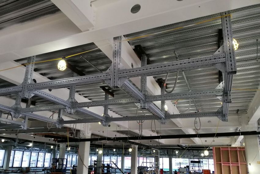
7.1 Address seismic restraint early in a project’s design life
A term sometimes used is “just in time design” where the restraint design is being finalised as the services
are being installed. A better approach would be to have regular reviews throughout the design process so
that changes to ensure a complaint and robust seismic restraint design can be implemented before this
becomes time critical.

Photo 4; from Wellington Children hospital where frames were restraint design was considered early and
suspended frames were used to support and restrain services.

7.2 Understanding of seismic restraint requirements
The current approach to locating services often does not consider how seismic restraint will be achieved. For
example, consideration that to provide a lateral restraint, a 45 degrees brace will be required and space be
allowed for this. If heavy services can be located close the primary structure (close to the soffit of the slab
over or against a primary beam) then the demands on the restraint system would be less.
This consideration does not always occur due to consultants (particularly Mechanical Electrical Hydraulic
consultants) not understanding seismic restraint requirements and how these will be achieved. If a seismic
restraint specialist were involved during the concept design stage, restraint requirements could be discussed
and strategies developed. This might involve identifying and agreeing key areas where services are intense
and agreeing that bracing individual services is not a viable option and a frame option strategy will need to
be adopted. Simple stick frames could be allowed for in the services model and services positioned to allow
for these so that there is a placeholder in the model. In areas that are identified as not services intense, the
modelling code should proceed assuming suspended service runs will be restrained individually or on a
shared trapeze.
The creation of a seismic restraint “challenges” (risk) register could indicate the seismic restraint challenges
and how it is envisaged these could be solved. This way at least, there is a record of an issue that will need
to be resolved later.
We consider that greater understanding needs to be imparted across design teams and needs to include the
Mechanical Electrical Hydraulic (MEH) consultants, the Architect, Fire and Acoustic Engineers, the
Structural Engineer, project managers, and the client. At the moment this is not occurring well and similar
issues keep occurring on each new project.
Some examples where this occurred on the ASB project;
1. The locations of heavy items of plant and equipment not being discussed and considered between the
   Services Engineers and the Structural Engineer.

Paper 145 – Lessons learnt during the seismic restraint design for the Acute Services Building at …

NZSEE 2021 Annual Conference
2. In the case of bulkhead walls, the design required of the Fire and Acoustic Engineer and the Structural
   Engineers were not coordinated.
These issues arose because the various consultants “didn’t know what they didn’t know”. This is common
across the industry when it comes to seismic restraint design.

7.3 Other “nice to have” considerations.
Other considerations we would recommend for similar IL4 Hospital Projects:
1. Be generous on area/space (do not skimp on area/space to save cost). This would apply to both plant
   rooms and plenum spaces. Provision of adequate room to locate and appropriately restrain services will
   result in a more successful (less compromised) restraint design.
2. Have the design team prepare a list of plant equipment, and equipment that could be used on the project
   that is both seismically qualified and meets performance specifications. Design work for seismic
   restraint and for the primary structure (for example slabs under heavy items of plant) could proceed
   based on items on the list. If the contractor selects an item that is not on this list and there are knock-on
   effects or cost implications, then these can be clearly identified. If there is no “place holder” for items of
   plant and equipment the cost implications are difficult to attribute.
3. Maintain a seismic restraint decision register. This may be similar to a Safety in Design Register or
   project risk register. The seismic restraint decision register would list potential seismic restraint issues
   and indicate how these should be addressed. A seismic restraint specialist would be required to help
   prepare this. This approach means that even if issues are not solved immediately, they are at least
   identified, and strategies developed to solve the issue. At the very least, a good seismic restraint decision
   register would highlight issues for a contractor to consider.
4. Before tendering, ensure the expectation that plant and equipment be seismically qualified is clear in the
   project specifications. This should include outlining methods that can be used to show qualification.

8   CONCLUSIONS AND RECOMMENDATIONS
This paper has described a significant seismic restraint design for a large Importance Level 4 hospital
building. This paper notes some of the challenges that occurred. This paper also makes recommendations
on how the seismic restraint design process could be carried out more effectively on future projects. These
recommendations include:
1. Consider the seismic restraint design early in the design life of a project.
2. Foster a greater understand of seismic restraint requirements with clients, project managers, architects,
   structural engineers, MEH consultants, fire engineers, acoustic engineers, and contractors.
3. Encourage design teams to work more collaboratively to understand issues in order to achieve better
   seismic restraint solutions.
4. Be generous on size allowed for to locate services. This would be in terms of space in plant rooms and
   the heights of ceiling plenums.
5. On significant projects maintain a seismic restraint decision register to record key decisions, restraint
   issues, and strategies to solve restraint issues.
6. Have a working seismic restraint design before tendering so that the cost of seismic restraint is
   adequately allowed for in the contract.
7. Ensure the expectation that plant and equipment is seismically qualified is clear in the project
   documentation including methods that can be used to show qualification.

Paper 145 – Lessons learnt during the seismic restraint design for the Acute Services Building at …

NZSEE 2021 Annual Conference
9    ACKNOWLEDGMENTS
We would like to acknowledge and thank the following people who play a key to the success of this project:
•   The CPB Team and in particular Mark Ballantyne, William Hill and Alan Leeder.
•   James de Lisle and Elisha Khan from Silvester Clark. James helped “problem solve” for the better part
    of two years during construction. Elisha inspected a significant portion of the 21,000 restraints.
•   Simon Mobley and the asBUILT team who modelled the restraints.
•   James Alcock from KME who lead the team that responsible for the installation the bulk of the restraints
    to suspended services.
•   Terry Johnson from Review Seismic who provided invaluable advice and assistance. Terry passed away
    in 2017.

10 REFERENCES
Holmes Consulting Group Memo,16 September 2015, Subject: Christchurch Hospital Redevelopment – Acute Services
  Building Seismic Performance Criteria, Holmes Consulting Group, Christchurch Central, Christchurch, New Zealand
NZS4219 (2009) Seismic Performance of Engineering Systems in Buildings, Standards New Zealand, Wellington, New
  Zealand.
NZS4541 (2013), Automatic fire sprinkler systems – Standards New Zealand, Wellington, New Zealand.
NZS1170.5 (2004). Structural design actions, Part 5: Earthquake Actions – Standards New Zealand, Wellington, New
  Zealand.
NZS3404:Part 1 (1997) Steel Structure Standard- Standards New Zealand, Wellington, New Zealand.
Reveal Seismic Memo, Project CDHB Christchurch Hospital- Acute Services Building Re: Proposal for Adoption of
  OSHPD Rugged Equipment List, 23rd May 2016, Reveal Seismic NZ Limited, Masterton, New Zealand.
ACI156, Acceptance Criteria for seismic certification of Shake-Table Testing of Non-structural Components, November
  2010, International Code Council (ICC) Evaluation Services.
Holmes Consulting Group Memo, 11 May 2017, Subject: Christchurch Hospital Redevelopment – Comflor Point Load
  Capacity, Holme Consulting Group, Christchurch Central, Christchurch, New Zealand.
Beca Specification, CDHB Christchurch Hospital – Acute Services Buildings – Electrical, 7 March 2016, Beca Ltd, New
  Zealand.
Beca Specification, CDHB Christchurch Hospital – Acute Services Buildings – Plumbing & Drainage, 7 March 2016,
  Beca Ltd, New Zealand.
Beca Specification, CDHB Christchurch Hospital – Acute Services Buildings – Medical Gases, 4 March 2016, Beca Ltd,
  New Zealand.
Beca Specification, CDHB Christchurch Hospital – Acute Services Buildings – Mechanical, March 2016, Beca Ltd, New
  Zealand.
Structural Drawings for the Christchurch Hospital Acute Services Building, Holmes Consulting Group, Holmes
   Consulting Group, Christchurch Central, Christchurch, New Zealand.
Structural Specification, Christchurch Hospital Redevelopment, February 2016, Holmes Consulting Group, Christchurch
   Central, Christchurch, New Zealand
Office of Statewide Health Planning and Development (OSHPD), Code Application Notice, Subject: Certification of
  Equipment and Nonstructural Components, CAN No. 2-1708A.5, Office of Statewide Health Planning and
  Development, California, United States of America.

Paper 145 – Lessons learnt during the seismic restraint design for the Acute Services Building at …

NZSEE 2021 Annual Conference
You can also read