LIUTO Development and Optimisation of the Propulsion System; Study, Design and Tests

Page created by Alfred Ferguson
 
CONTINUE READING
LIUTO Development and Optimisation of the Propulsion System; Study, Design and Tests

G. Bertoloa, A. Brighentib, S. Kaulc and R. Schulzed
a
 ACTV, Azienda Consorzio Trasporti Veneziano
San Marco 3880,Venezia, Italy
b
 Systems & Advanced Technologies Engineering S.r.l.,
San Marco 3911,Venezia, Italy
c
 SCHOTTEL Shipyard, JOSEF BECKER GmbH & Co. KG
D-56322 SPAY, Germany

d
 Propellerhydrodynamics , Schiffbau-Versuchsanstalt Potsdam GmbH
Marquardter Chaussee 100, D-14469 Potsdam, Germany

    In fall 1996 ACTV, the two industrial companies SCHOTTEL WERFT and INTERMARINE and the three
R&D institutions University of Naples (DIN), Maritime Research Institute Netherlands (MARIN) and Schiffbau-
Versuchsanstalt Potsdam (SVA), with the financial support of the EC Brite-Euram programme, started an R&D
project to develop and full scale test a new motor boat for public urban transports, to be used in water cities, such
as primarily but not exclusively Venice.
    LIUTO (Low Impact Urban Transport water Omnibus) is the name of the project, whose goal is to develop
the prototype of Venice’s 2000 M/b fleet with the following main aims and innovative features:
    • achieve low hydrodynamic impact by wave and propeller washing generated in the navigation and the
         frequent manoeuvring, by means of an optimised hull and an innovative propeller designs;
    • qualify and compare results with existing vessels by validated CFD numerical tools, model and full scale
         tests;
    • test and apply composite materials, resisting heavy duty services, vandalism and environmental
         conditions, for the hull construction and the superstructure, to reduce maintenance costs and help
         achieving stability.
    ACTV is responsible for co-ordinating the project and defining, as prime interested end user, the specification
of the motor boat. This will also feature innovative technologies for propulsion energy generation (a hybrid diesel
electric system with buffer batteries) and external and internal noise limitation which are the object of concurrent
activities under ACTV own support.
    This paper after an overview of the vessel operational profile develops in greater detail the characteristics of
the propulsion system.

                                                                  Fixed axis propellers and manoeuvring by rudder
1.   OPERATIONAL PROFILE
                                                              cause a significant turbulence and jetting in areas
                                                              near berths, canal turns and buildings foundations.
    The passenger transport system of the city of
                                                                  The LIUTO characteristics (Table 1) allow an
Venice and its lagoon relies on a fleet in excess of
                                                              efficient and environmentally friendly operation in a
110 vessels, among water busses (54 M/B) and
                                                              variety of lines, both across the city and between the
motor crafts (59 M/S). They have steel hull and are
                                                              central Venice and the nearby islands.
powered by diesel engines. Their navigation pattern,
                                                                  The optimisation of the vessel took into account
compared to other water transports, features a wide
                                                              particularly the most important service lines,
variation of payload and displacement, varying speed
                                                              involving the crossing of the central urban area along
limits, relatively high acceleration and deceleration
                                                              the Grand Canal (30-60 m wide) and the larger
performances, for timetable optimisation and safety
                                                              Canal of Giudecca by very frequent stops (one every
in the very congested urban traffic.
                                                              2-3 minutes) and prevailing transient power
                                                              conditions.
LIUTO Development and Optimisation of the Propulsion System; Study, Design and Tests
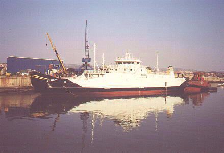
Traffic is there intense and congested. The          gradually shift from present pilots practice to the
service must comply with the speed limits stated by      improved features offered by the directional thruster.
the competent authorities to keep boats waves low,           An important requirement of the propulsion and
respectively the Borough of Venice for the canals in     energy system is its capability to stop the vessel in a
the historical centre of the city and the Harbour        short distance both during regular service and when
Authority, for the larger canals for the maritime        in emergency, e.g. to avoid collisions with crossing
navigation.                                              vessels. To limit the hydrodynamic impact under
    The LIUTO design and main test conditions thus       normal operation it should be avoided to exceed
cover the following basic speed requirements, in         certain power limits, by a relatively “smooth” power
calm waters and no wind conditions:                      demand attitude, within the nominal motor
                                                         performances.      Instead      during      occasional
   V1 urban speed                   5.94      knots
                                                         emergencies these power limits should be overcome
   V2 max full load speed          10.0       knots      allowing a stop within 2.5 x LOA from the speed of
                                                         10 kn and within 1 x LOA from the speed of 5.94 kn.
   V3 max half load speed          10.8       knots          The power to the thruster motor is thus managed
                                                         by a supervisory control system that is also in charge
                         S. 80       E1        LIUTO     of the efficient and safe management of the whole
                        Existing   Existing     New      hybrid energy system.
Passengers                219        208         234
capacity                                                   2. HYBRID PROPULSION ENERGY
                                                         SYSTEM
Seats                     83         72          100
Displ. (ls./fl.)   t     39/57      35/50       34/50        The LIUTO energy system will be a series type,
                                                         hybrid diesel electric system as shown in Figure 1,
Length B.P.        m     21.0       20.9         24.7    including the following main components:
Max Speed          kn    11.5        8.9         10.8    • diesel engine, running at constant speed
                                                         • 3-phase synchronous electric generator
Constr. height m         1.85       1.90         2.03    • 3-phase rectifier
Driver     cont. kW       147        60           90     • batteries stack (high charge/discharge rate lead-
power                                                        acid with gel type electrolyte)
                                                         • power management and battery charge control
Type          of         Diesel    Electric     Hybrid   • inverter unit
driver                                                   • 3-phase asynchronous electric motor
                                                         • Interface mechanical coupling with the
  Table 1 - Comparison of the LIUTO characteristics          propulsion system drive shaft
             with present ACTV M/bs                          The system was studied in cooperation with the
                                                         University of Naples Department of Naval
    The full range of operational water depths goes      Engineering [1,2] after detailed analysis of existing
down to 2 m in the shallowest areas of the canals, the   vessels performances and is now being designed and
most common falling between 3 and 10 m.                  manufactured by ANSALDO, under ACTV contract.
    The manoeuvrability will also be improved with           The gen-set converts all the mechanical energy
respect to present M/bs, presently characterised by      delivered by the diesel engine into AC electric
25 m turning radius, with a rudder angle of 42°.         energy. This is then rectified and supplied in parallel
    The choice of a directional propeller goes with      to the battery stack and the user functions, the main
this target, as it allows continuous 360° thrust         one being the propeller AC asynchronous motor, fed
direction variation. The maintained possibility of       by the inverter. This latter operates at variable
reversing the propeller revolution, thanks to the        frequency and voltage, as shown in the control loop
electric drive provided by a hybrid energy system,       dotted in Figure 1.
allows maximum flexibility and possibility to
LIUTO Development and Optimisation of the Propulsion System; Study, Design and Tests
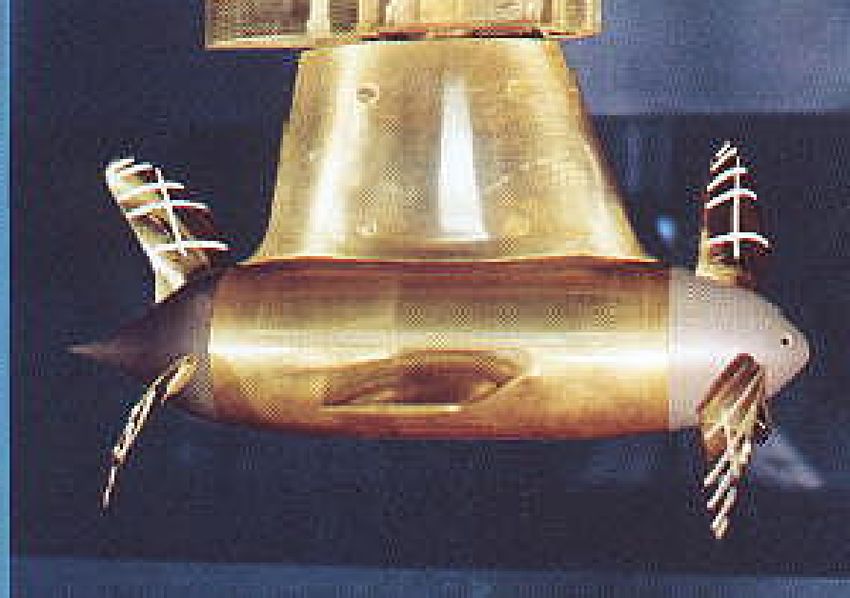
Power management controller

                                                                                                           Speed command handle

     n rif.                                           By-pass switch
                                             P rif.                                 Np rif.

                                V > Vmax

                                             C. I                                    C. Np
     C. n
                                                                                                                   T. Np
                T. n

      M.T.                                                A                                               M. AC

                                                      I ~ const.        V                     V = V(t)
                                                       V = V(t)                                f = f(t)

                                                                               240 V
                                                                               Batteries

     Figure 1 - Scheme of the hybrid system and its main control structure - Feedback to battery charger (T =
         transducer, C = controller). The main and the emergency AC motors are shown as a unique one.

     The power generating set runs at either no power              LIUTO. Propellers with different diameters and
(idle or off) or at a single power level. The battery              optimum numbers of revolutions have been
stack features mostly peak power supply and energy                 designed. The calculations showed that a propeller
buffer, under very high but short charge/discharge                 diameter of D ≈ 0.750 m should be used.
power levels.                                                          Different propulsion systems are practicable for
     The system is twofold redundant, against failure              the water omnibus. Aspects of the propulsion
of any of the static or rotating subsystems. If the                systems conventional propeller, propeller made out
inverter fails a by-pass switch allows the AC                      of fibre reinforced material, ducted propeller,
generator to directly drive an emergency, lower                    SCHOTTEL Twin Propeller and LINEAR-Jet have
power, AC motor (not shown in Figure 1). The                       been discussed
batteries are made by two stacks in parallel, that can                 Finally a new Z-drive was designed. An
individually be isolated, keeping the system                       optimised, streamlined shape of the lower gearbox
operational, yet at lower power performance, if                    housing with low drag was realised. The drag of the
either fails. Should the engine, the generator or the              housing is 3 - 5 % lower than at conventional shaped
rectifier fail instead, the energy capacity of the                 housings. The influence of the housing on the
battery stack is largely sufficient to complete the                propellers was minimised. This means that the
mission and go to the repair yard, with the engine                 increase of thrust and torque coefficient and the
off.                                                               decrease of the efficiency caused by the disturbed
                                                                   wake field due to the housing could be reduced
                                                                   distinctly. Compared with the state of the art it can
   3. PROPULSION SYSTEM DESIGN
                                                                   be stated that there is no housing existing today with
                                                                   such outstanding stream properties. The use of
   3.1. Propulsion unit generally
                                                                   spheroidal cast iron makes it possible to realise
   SVA and SCHOTTEL-Werft were in charge and
                                                                   streamlined laminar profiles with an unconventional
have developed an efficient propulsion system for
form with an optimised relation of length to             Because of the low rotational inertia it is possible to
thickness. The blades camber and the angle of attack     relinquish an additional elastic clutch at the cardan
was optimised in model tests so that flow separation     shaft. A propeller weight saving of approx. 65 %
is completely prevented. Previous investigations         could be achieved compared to standard materials.
about asymmetrical arrangement of the shaft showed
that the spin recovery can be improved but the
                                                            4. PROPULSION SYSTEM
resistance of the housing increases in the same value.
Therefore the symmetrical version was chosen.
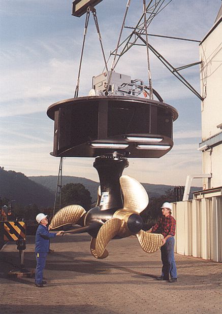
                                                             4.1 The TWIN-Propeller
                                                             The     TWIN-Propeller      Technology,      is
                                                         characterised by two propellers on the same shaft
                                                         with the same rotation direction and a guide
                                                         arrangement between the propeller (Figs. 3,4,5).

  Figure 2 - 3D-Drawing of the Lower Gear Box

    3.2. Materials - Propellers and Foils / Fins
    Propellers are available normally in CuNiAl or         Figure 3 - SCHOTTEL-Twin Propeller, Standard
manganese-bronze and, for special fields of                                 Version
operation, even in stainless steel. For the LIUTO-
project it is suitable to have parts with low weight         This results in improvement of efficiency and
due to the frequent speed reversals. In this case the    noise emission (pressure fluctuations) for two main
use of unconventional materials (carbon fibre            factors:
reinforced material) for the propellers and the              a. Power distribution at two propellers: a
foils/fins of the TWIN-Propeller was examined.           lower thrust load of each propeller reduces the
    It was the first time that such kind of propeller    impulse losses. The blade geometry of both low
was driven at a Z-drive with it’s special operation      loaded propellers can thus be designed in a more
conditions (oblique flow during steering, disturbed      efficient way (profile geometry, chord-length,
wake field due to the housing etc.)                      thickness, camber etc.). Interference effects among
    The manufacture of this kind of propeller has        the blades are by comparison lower than in a high
shown a very high accuracy. The material’s very          loaded single propeller, usually designed with a
good damping properties lead to operation with low       higher number of blades. Furthermore this power
noise and pressure vibrations. Another effect is the     distribution leads to low level of cavitation and
positive influence to the elastic mass system.           pressure fluctuation, which cannot be achieved by
another system.                                        forward
   b. Recovery of lost spin energy: lost spin              SCHOTTEL has delivered or in order 26 STP-
energy is recovered and flow is directed to the rear   units in a power range from 80 kW to 1250 kW. For
propeller by using an integrated guide arrangement     example some Double Ended Ferries for Norway,
consisting of a specially formed housing and           among which one is equipped with two STP 1010 ( 2
additional guide fins.                                 x 1250 kW). The STP-units enable an efficient
                                                       operation at low noise and high degree of
                                                       manoeuvrability. Extensive tests were done recently
                                                       and confirmed the excellent performance of the
                                                       units. The full scale test results were also very close
                                                       to the model based predictions.
                                                           SCHOTTEL is using the Twin-Propeller
                                                       Technology also in PoD-Propulsion. In co-operation
                                                       with SIEMENS AG SCHOTTEL has developed the
                                                       SSP. The SSP is a podded electric drive available in
                                                       a power range from 5 to 30 MW. A new permanently
                                                       excited electric motor from SIEMENS is integrated
                                                       in the underwater gondola of the Rudderpropeller.
                                                       Boths propellers are driven directly. The motor is the
                                                       most efficient and smallest electric motor that is built
                                                       today. Therefore a very slim streamlined gondola
                                                       with a low resistance has been developed.
 Figure 4 - Hydrodynamic model of a SCHOTTEL-          The combination with the TWIN-Propeller
                  Twin-Propeller                       Technology leads to a convincing PoD-Propulsor.
                                                           The TWIN-Propeller Technology was a big step
                                                       to improve the efficiency of high loaded rudder-
                                                       propellers. Using the same technology with two plus
                                                       two bladed propeller system is the consequent
                                                       development for low loaded rudder-propellers.
                                                           LIUTO made it possible to examine such systems
                                                       and to approve it in practice.
                                                           It was the first examination of 2-bladed TWIN-
                                                       Propeller. The investigations include theoretical
                                                       calculations, model tests in cavitation tank and full
                                                       scale tests with a prototype at test pontoon of
                                                       SCHOTTEL.
                                                           The safety against cavitation is given by the fact
                                                       that each one of the two propellers is driven with
                                                       lower load and the total propeller load of the
                                                       LIUTO-vessel is very low too.
                                                           The result is an additional efficiency increase by
                                                       using 2-bladed propellers was achieved. The
                                                       mechanical problems of 2-bladed propeller systems -
                                                       the torsional vibrations and the pressure vibrations -
    Figure 5 - Computed wake distribution in the       could be solved by a special blade geometry, a
          position of the second propeller             comfortable distance between propeller and housing
                                                       and by the use of very light propeller blades made of
                                                       carbon fibre reinforced material.
                                                           The procedure of calculation of 2-bladed TWIN-
   4.2. Previous developments and LIUTO’s step         Propeller and the transformation of the model test
results to full-scale values was verified.

                                                                                                                                  Figure 8 - SSP 7 TWIN-Propeller as PoD-Propeller
                                                                                                                                       (test model in the SVA cavitation tunnel
         Figure 6 - Double Ended Ferry, MRF-Norway

    Propulsor room                                                                                 Slipring unit for main
                                                                                                   and auxiliary energy

       Hydraulic motor and planetary gear
       combination (multiple)

                                                                                                      Electro-hydraulic
   Azimuthing slewing                                                                                 steering system
   bearing                                                                                            (multiple)

     Azimuth module
                                                                                                                     Support
       Auxiliary device                                                                                              cone

                                   Hull line
                                                                                                               Bilge system
                                                                                                               pumps

                                                                                                                     Propeller
                                                                                                                     shaft
   Propulsion module                                                                      Strut

                                                                                                                     Front
                                                                                                                     propeller
                                 Internal
                                 cooling
                                 system
 Rear
 propeller

    Rotor
    coupling

                                                                            PEM
                                                                            synchronous
                                 Rear          Bearing-, sealing-,                         Front
 Cap                             bilge         brake system          Fins   motor                                           Cap
                                                                                           bilge

Figure 7 - SSP 7 TWIN-Propeller as PoD-Propulsor

                                                                                                                                         Figure 9 - SCHOTTEL- STP 1010
η 0 / [−]                                                                         SW-TFI
  0.9                                                                                  date: 23/07/1997
                                                                                       name: S. Kaul
                          x     x    ETA0 Contour(F) Propeller Z-Drive
                                     ETA0 Optimised Propeller Z-Drive
  0.8                                ETA0 Twin Propeller Z-Drive
                                     ETA0 Conventional Propeller Z-Drive                         LIUTO
                                                                                           Open Water Tests
  0.7

                                                                                               η 0 = f (C
                    xx
                                                                                                            TH )
  0.6                     x x
                                      x
                                                    x
                                                                       x
                                                                                       Propeller Design Based on
                                                                                       Resistance Prognosis SVA
  0.5

  0.4                                                                                  Without Mechanical Losses

  0.3
     0.75 0.8 0.85 0.9 0.95 1                               1.5                    2   measurement:SVA

                                                                           CTH / [-]   file: T:...\LIUTO\MODVER01.DAT
                                                                                       graph: T:...\MODVER09.LPD

               Figure 10 - Model Test Result, Comparison of the different Systems studied for LIUTO.

    4.3. CONTOUR(F/S)-Propeller                               automatically. Therefore overload can be reduced
    The CONTOUR(S)-Propeller is a specially                   and the engine operates at better conditions.
designed propeller. Carbon fibre reinforced                       The theoretical pre-calculation led to an
composites enables a very slim profile geometry.              efficiency increase of 2 % at higher ship speed and
This kind of profile geometry leads to a higher total         up to 10 % at low speed (overload conditions).
efficiency of the propeller.                                      There are still some difficulties of the fibre
    The combination of CONTOUR(S)-design and                  structure design to achieve the hydrodynamic
the TWIN-Propeller join the mechanical advantages             parameters at each operation point.
of the light and highly accurate manufactured                     Therefore for the LIUTO M/b prototype the 2
propeller with a new hydrodynamic technology. The             blade STP is being made by CONTOUR(S) type
result: propulsion system with highest efficiency for         blades.
the LIUTO vessel.                                                 Further research work is required to control the
    The CONTOUR(F)-Propeller is the flexible type             deformation characteristic. A lot of companies all
of CONTOUR-Propellers which deforms in                        over the world have started the development of such
operation in a defined way depending on the load.             systems.     The interest in this technology has
That leads to an optimum efficiency in a wide range           increased. Special installations are military and
of operation. For example, at overload conditions             hydrographical ships or special requirements on
(stopping, acceleration) the pitch ratio is reduced           environmental protection aspects for example.
PFFEDIT                                                                                                                                                                                                 on ship hull
the routine PFFEDIT yields                                                                                                                                                                          • the strength.
the propeller draw and                                                       r/R
                                                                            1.000
                                                                            .9500
                                                                                    Chord[mm] P[mm]
                                                                                       52.08
                                                                                       248.9
                                                                                                 1022.
                                                                                                 1022.
                                                                                                             Skew[x]
                                                                                                            2.076
                                                                                                            3.792
                                                                                                                         Rake[mm]
                                                                                                                        -109.6
                                                                                                                        -97.62
                                                                                                                                   3.376
                                                                                                                                   11.84
                                                                                                                                        F[mm]   T[mm]
                                                                                                                                            7.000
                                                                                                                                            10.40
                                                                                                                                                         Propeller: P1257_2G
                                                                                                                                                                Z   :

                                                                                                                                                               D[m] :
                                                                                                                                                               AE/A0:
                                                                                                                                                                           5
                                                                                                                                                          Direction : right handed
                                                                                                                                                                           1.4000
                                                                                                                                                                           .62000
                                                                                                                                                                                                        The usual strategy for the realisation of the
                                                                                                                                                          P/D(0.7r):       .73000

                                                                                                                                                                                                    design process consists in a iterative trial and error
                                                                            .9000      312.1     1022.      2.693       -86.53     10.85    13.80
                                                                                                                                                          F/C(0.7r):       .17690E-01

represents the main data as a
                                                                            .8000      370.1     1022.      .7271       -66.96     7.543    20.60
                                                                                                                                                           Skew[x]:        9.7987
                                                                            .7000      390.1     1022.      -1.039      -50.63     6.901    27.40
                                                                                                                                                          C(0.7)[m]:       .39008
                                                                            .6000      389.4     1022.      -2.576      -37.22     8.812    34.20
                                                                                                                                                          PFFDRAW (DIN 85 646)
                                                                            .5000      375.5     1022.      -3.901      -26.42     11.69    41.00
                                                                            .4000      351.2     1022.      -4.971      -17.93     13.77    47.80                   25.07."96 (C) R.S.
                                                                            .3000      318.0     1022.      -5.761      -11.43     13.59    54.60

                                                                                                                                                                                                    algorithm to
                                                                            .2000      277.8     1022.      -6.007      -6.598     10.48    61.40

function of the radius r
VTXPLOT
                                   KTKQPLOT: KT[-],10KQ[-],Eta0[-] ov er J[-] : f iles: p1257.v 10    ,

                                                                                                                                                                                                    • increase the propeller efficiency

                                                                                                                                                                    .600
                                   .000        .100         .200         .300         .400           .500        .600            .700       .800        .900     1.00
                                                                                                                                                                               P1257 - Propeller

                                                                                                                                                                                                    • decrease the cavitation on blades and the

                                                                                                                                                                    .500
yields the graph of KT, 10KQ

                                                                                                                                                                    .400
and η0 as a function of J or                                                                                                                                                                            fluctuation pressure on ship hull.

                                                                                                                                                                    .300
Cth, the graph of the cavitation                                                                                                                                                                        This iteration process can be started with a

                                                                                                                                                                    .200
                                                                                                                                                                    .100
buckets                                                                                                                                                                        25.07."96 (C) R.S.

                                                                                                                                                                                                    conventional design method such as some series

                                                                                                                                                                    .000
DENPLOT                                                                                                                                                                                             charts techniques.
represents the vortex strength                                                                                                                                                                          The calculation for propellers can be
distribution                                                                                                                                                                                        accomplished by using the lifting line and the lifting
                                                                                                                                                                                                    surface theories under steady and unsteady
                                                                                                                                                                                                    conditions respectively.
                                                                                                                                                                                                        Contrary to the trial and error strategy we
CAVPLOT
                                                                                                                                                                                                    determine the propeller geometry by an optimization
represents the cavitation
                                                                                                                                                                                                    technique.
bucket     chart   and  the
cavitation behaviour of the
                                                                                                                                                                                                       5.2. Inverse methods for the design and
blades in the wake (regions
                                                                                                                                                                                                    optimisation of marine propellers
with critical pressure are
                                                                                                                                                                                                       The strategy of Potsdam Ship Model Basin
marked)
                                                                                                                                                                                                    consists of the construction of a “Toolbox Propulsive
WAKPLOT
                                                                                                                                                                                                    Performance Optimisation“
represents the wake
                                                                                                                                                                                                    • definition of a “weighting function“ to determine
                                                                                                                                                                                                       the propeller efficiency (η), cavitation behaviour,
                                                                                                                                                                                                       etc.
                                                                                                                                                                                                    • variation of the propeller geometry by an
VELPLOT                                                                                                                                                                                                optimisation algorithm
computation                 and                                                                                                                                                                     • calculation of propellers by using series charts
representation of the velocity                                                                                                                                                                         techniques lifting line methods lifting surface
distribution     around      the                                                                                                                                                                       methods NSE-Solver
propeller (in the propeller jet)                                                                                                                                                                       The geometry (G) of propellers can be described

   Table 2 - Components of the numerical cavitation
        tunnel of the SVA-Potsdam GmbH                                                                                                                                                                   r/R     c    P/D rake    Xe       f/c    t/c
                                                                                                                                                                                                        .200 479.71 1.10 .000 295.41 .0385 .118

   5. PROPELLER DESIGN BY SVA                                                                                                                                                                           .400 587.56 1.20 .000 352.51 .0274 .074
      POTSDAM                                                                                                                                                                                           .600 641.93 1.30 .000 358.32 .0202 .047

   5.1. Introduction                                                                                                                                                                                    .700 636.72 1.40 .000 335.21 .0171 .037
   A modern design method for marine propellers is                                                                                                                                                      .900 486.39 1.30 .000 194.56 .0111 .022
in general based on a collection of computer
                                                                                                                                                                                                        1.000   20.00 1.20 .000   .000    .00000 .000
programs (Table 2) to calculate
• the propeller - hull interaction
• the propeller - machine interaction                                                                                                                                                                      Table 3 – Propeller geometry definition
• the propulsive performance which includes                                                                                                                                                          (c, P/D, rake, Xe, f/c and t/c are functions of r/R.)
   propeller efficiency
• the cavitation on blades and fluctuation pressure
by (e.g. 42) real numbers like in Table 3.                                                                                      KTJplot: KT[-],10KQ[-],Eta0[-],SigN/10 over J[-] : 97kt283z.mes
                                                                                                                                .000   .100     .200        .300   .400           .500   .600   .700    .800   .900   1.00
                                                                                                                                                                                                                             .700    P1288
    The geometry G of the “best propeller“ in the                                                                                                                                                                                    TP1286/1287

sense of efficiency (η) is the solution of the                                                                                                                                                                               .600

following optimisation problem:                                                                                                                  KQ
                                                                                                                                                                                                                             .500

                                                                                                                                                       KQ

                                f(G) := η0(G) ===> max !                                                                                         KTT
                                                                                                                                                                                                                             .400

                                                                                                                                                  KTT

                                                                                                                                                       eta0T                                                                 .300

                                                                                                                                                 eta0T

                                                                                                                                                                                                                             .200

                                                                                                                                                                                                                             .100      02-Jun-98
                                                                                                                                                                                                                                      (C) R. Schulze

                                                                                                                                                                                                                             .000

                                                                                                                        Figure 13 - Comparision of the single optimised pull-
                                                                                                                        propeller P1288 (continuous line) and the Twin-
                                                                                                                        propeller-system TP1286/1287 (dotted line), with the
                                                                                                                        influence of the Z-drive.

Figure 11 - SVA test facility (Kempf and Remmers)
                                                                                                                         GAIplot: Gain[%] over Cth[-] with respect to: 97kt283z.mes
for the SCHOTTEL - TWIN - Propeller                                                                                      .100                 1.000                       10.00                 100.0             1000.
                                                                                                                                                                                                                       20.0         P1288
                                                                                                                                                                                                                       19.0
                                                                                                                                                                                                                       18.0
                                                                                                                                                                                                                       17.0         TP1286/1287
                                                                                                                                                                                                                       16.0
                                                                                                                                   Gain                                                                                15.0
     KTJplot: KT[-],10KQ[-],Eta0[-],SigN/10 over J[-] : liu_WAGZ.wag
                                                                                                                                                                                                                       14.0
     .000   .100    .200   .300    .400   .500   .600   .700   .800   .900   1.00   1.10 1.20
                                                                                                .700                                                                                                                   13.0
                                                                                                       B4055095
                                                                                                                                                                                                                       12.0
                                                                                                                                                                                                                       11.0
                                                                                                       P1288
                                                                                                                                                                                                                       10.0
                                                                                                .600                                                                                                                   9.00
                                                                                                                                                                                                                       8.00
            KQ                                                                                                                                                                                                         7.00
                                                                                                                                                                                                                       6.00
                                                                                                .500                                                                                                                   5.00
                           KQ                                                                                                                                                                                          4.00
                                                                                                                                                                                                                       3.00
                                                                                                                                                                                                                       2.00
                                                                                                .400                                                                                                                   1.00
                                                                                                                                                                                                                       .000
            KTT
                                                                                                                                                                                                                      -1.00
                           KTT                                                                                                                                                                                        -2.00
                           eta0T
                                                                                                .300                                                                                                                  -3.00
                                                                                                                                                                                                                      -4.00
                                                                                                                                                                                                                      -5.00
                                                                                                                                                                                                                                     02-Jun-98
                                                                                                                                                                                                                      -6.00         (C) R. Schulze
                                                                                                .200                                                                                                                  -7.00
                                                                                                                                                                                                                      -8.00
                                                                                                                                                                                                                      -9.00
                                                                                                                                                                                                                      -10.0
            eta0T                                                                               .100    02-Jun-98
                                                                                                       (C) R. Schulze

                                                                                                .000                        Figure 14 - Comparision of the single optimised
                                                                                                                        pull-propeller P1288 and the Twin-propeller-system
Figure 12      - Comparison of the open water                                                                           TP1286/DP1287/Z-drive, efficiency gain over CTH
behaviours of a single Wageningen propeller                                                                             [%] with respect to P1288.
(continuous line) with the optimised SVA-propeller
P1288 (dotted line), with the influence of the Z-drive.
                                                                                                                        • open water tests with the z-drive housing and the
                                                                                                                          pull propeller (dynamometer J 25, balance R
                                                                                                                          35X). (control of the pitch ratio for the design
    6. MODEL AND FULL SCALE TESTS                                                                                         point of the pull propeller)
                                                                                                                        • open water tests with the z-drive housing and the
    6.1 Model Tests of the SCHOTTEL Twin                                                                                  pull and push propeller (dynamometer J 25, H
Propeller (SVA design TP1286/1287)                                                                                        36, balance R 35X). (control of the pitch ratio for
    The tests performed at SVA followed the steps
                                                                                                                          the design point of the push propeller and the
listed herebelow:
                                                                                                                          STP)
• open water tests with the first and the second
                                                                                                                        • open water and cavitation tests with a variation of
    propellers of the twin pair with the dynamometer
                                                                                                                          the phase angle between both twin propellers
    J 25
                                                                                                                          (fixing of the phase angle)
SIGPLOT: Cavitation Buckets for SigN over J[-]                                                             PROGNOS: PD[kW],n[1/s] over Vs[kn] : files: liuto98.wid
    .000    .100   .200    .300   .400    .500       .600   .700    .800    .900                               4.00   5.00    6.00   7.00    8.00    9.00    10.0    11.0   12.0   13.0          n= 20.0 [1/s]
                                                                                   16.0                                                                                                   1.00   P= 200. [kW]
                                                                                            VP1286
                                                                                                                                                                                                 RT= 15.0 [kN]
                                                                                   15.0
                                                                                            VP1287                                                                          RT            .900   LIUTO-RT
                                                                                   14.0

                                                                                   13.0                                                                                     P             .800
                                                                                                                                                                                                 B4055095
                                                                                   12.0
                                                                                                                                                                            P             .700   TP1286/1287
                                                                                   11.0

                                                                                   10.0                                                                                                   .600

                                                                                   9.00
                                                                                                                                                                                          .500
                                                                                   8.00

                                                                                   7.00                                                                                                   .400

                                                                                   6.00
                                                                                                                                                                                          .300
                                                                                   5.00

                                                                                   4.00
                                                                                                                                                                                          .200
                                                                                   3.00                                                                                                           02-Jun-98
                                                                                             02-Jun-98                                                                                           (C) R. Schulze
                                                                                                                                                                                          .100
                                                                                   2.00     (C) R. Schulze

                                                                                   1.00
                                                                                                                                                                                          .000
                                                                                   .000

                                                                                                                 Figure 17 - Comparison of delivered powers in
Figure 15 - Cavitation bucket of the Twin-propeller-
                                                                                                              dependence of the water omnibus speed (kn) for the
system TP1286/1287. The cavitation bucket of the
                                                                                                              Schottel-Twin-Propeller and a classical Wageningen
first propeller P1286 (continuous line) and of the
                                                                                                              propeller, with Z - drive correction (RT: resistance
second propeller P1287 (dotted line). Only the end
                                                                                                              curve. Continuous line: PD for the Wageningen
of the suction/pressure side cavitation depending on
                                                                                                              propeller. Dotted line: PD for the Twin-Propeller).
the advance coefficient was drawn.

    KTQNT: KT[-],10KQ[-],Eta0[-] over Beta[x] : files: 97kt284.mes , 97kt311z.mes
    90.0    100.   110.    120.    130.    140.      150.    160.    170.    180.
                                                                                    .000    P1288

                                                                                    -.304   TP1286/1287

                                                                                    -.608

                                                                                    -.911

                                                                                    -1.22

                                                                                    -1.52

                                                                                    -1.82

                                                                                    -2.13

                                                                                    -2.43
                                                                                              02-Jun-98
                                                                                             (C) R. Schulze
                                                                                    -2.73

                                                                                    -3.04

                                                                                                              Figure 18 - Test arrangement of a SCHOTTEL-
   Figure 16 - Crash stop manoeuvre for the                                                                   TWIN Propeller
Schottel-Twin-Propeller      TP1286/1287         in
comparison with the optimised pull propeller P1288                                                                6.2. Full Scale Tests
                                                                                                                  The test facilities at SCHOTTEL allow extensive
                                                                                                              examinations in full scale including the following
•          cavitation tests for all design points in                                                          tests like
           homogeneous inflow                                                                                       - Torsional Vibrations
•          open water tests for measuring the characteristic                                                        - Crash back
           of the STP during the reversing process                                                                  - Crash ahead
                                                                                                                    - Steering
                                                                                                                    - Load of the foils
                                                                                                                    - Bollard Pull
                                                                                                                  A careful comparison of full-scale tests and
model tests is an important step to show some scale        phase.
effects especially for new developments. This gave             The results of the simulations and of a sensitivity
the opportunity to verify model tests and                  analysis are summarised in Figure 22. With a torque
computerised calculations. In the case of LIUTO            overload factor of 1.4 both breaking requirements
full-scale tests confirmed the very good model tests.      are satisfied, the overload lasting 24 and 16 s
    After the parallel activities made in the project on   respectively. The peak motor power under these
the hull hydrodynamics optimisation and, in                conditions is 132 kW.
particular, after the resistance tests results on large        The electric motor shall withstand these
scale ship model, it could be confirmed that more          conditions only occasionally for the duration of the
than 60% efficiency is achieved over a large range of      breaking phase without damage, starting from the
LIUTO’s operational speeds (Figure 21).                    thermal state corresponding to a typical mission
                                                           power profile [Refs. 1, 2], without repetition of this
  7. CRASH STOP PERFORMANCE OF THE                         stress. Under normal operating conditions, instead
PROPULSION SYSTEM                                          the electric motor shall be used within its nominal
                                                           torque, yielding a breaking distance of 2.9 or 1.3
    An important aspect of the performance of              LOA, respectively from 10 and 5.94 kn, and a peak
LIUTO’s propulsion system is its breaking and              motor power of 76 kW.
acceleration performance, particularly the former as
regards safety. As after the discussion of the
operational profile under emergency conditions the
stop distance should be within the limits of 2.5 or 1
times the LOA, i.e. 63 and 25 m, respectively when
stopped from 10 and 5.94 kn respectively.

                                                           Figure 20 - 5 bladed model of the CONTOUR (F)
                                                           single rotor propeller (Carbon fibre reinforced
                                                           material).

                                                              8. CONCLUSIONS

Figure 19 - 2-Bladed Optimised Propeller for the               The LIUTO project is a step towards the
Twin-Propeller-System for LIUTO.                           achievement of low impact and efficient propulsion
                                                           systems. It pursued by a broad view of applicable
    To verify this performance and the requirement         solutions and extensive modelling and tests this goal
on the electric motor, inverter and batteries dynamic      and it achieved it.
simulations of the motor-mechanical transmission-              The most important results are:
propeller-ship dynamics were performed, based on           • the efficiency of the propulsion system
the characteristics of the vessel and the STP                   exceeding 62% for speeds going from 2 kn up to
propeller, derived from model tests. The dynamics               the maximum speed foreseen of 11 kn.
account for the delay in motor shaft acceleration to       • the acceleration and crash-back performances,
reverse the propeller speed and the variation of the            allowing a reduction of nearly 40% of the
propeller working point (KT & KQ vs. J) and ship                installed motor power with respect to present
total resistance at each time.                                  M/b’s.
    The electric motor is supposed to be driven at
constant negative torque during the whole breaking
J, KT, KQ vs. speed at stationary conditions

                                  0.80

                                  0.70

                                  0.60
                                                                                                        Eta
                                  0.50
                    J, KT, 10KQ

                                                                                                        J
                                                                                                        10KQ
                                  0.40
                                                                                                        KT
                                  0.30

                                  0.20

                                  0.10

                                  0.00
                                         0          1               2            3          4                 5           6            7
                                                                                  Speed (m/s)
                                                         Figure 21 – J, KT, KQ and η curves vs. LIUTO speed.

                                                         STOP DISTANCE AND TIME FROM 10 or 5.94 kn

                     3.50                                                                                                                  35

                     3.00                                                                                                                  30

                     2.50                                                                                                                  25
Stop distance/LOA

                                                                                                                                                Stop time (s)
                     2.00                                                                                                                  20

                     1.50                                                                                                                  15

                                                                                                                  Distance @ 10 kn
                     1.00                                                                                         Distance @ 5.94 kn       10
                                                                                                                  Time @ 10 kn
                     0.50                                                                                         Time @ 5.94 kn           5

                     0.00                                                                                                                  0
                                    1        1.1        1.2        1.3     1.4       1.5       1.6      1.7        1.8        1.9      2
                                                                         Motor torque overload factor

                                    Figure 22 - Stop distance and duration - Sensitivity analysis vs. motor torque overload factor.
ACKNOWLEDGEMENTS                                        [10] Contur-propeller, Contur(F)- Prospect AIR
                                                        Fertigung-Technologie GmbHRostock 1996
   The LIUTO project partners wish to                      [11] The SCHOTTEL Twin Propeller - an
acknowledge and thank the EC DGXII for the              propulsion system, SCHOTTEL Information, 75
support to this important project.                      Years SCHOTTEL, 10th August 1996
                                                           [12] Jürgens,     Der    LINEAR-Jet      -    ein
   REFERENCES                                           Propulsionssystem          für        flachgehende
                                                        Wasserfahrzeuge, Fachkongreß ROTECH Rostock,
    [ 1 ] Balsamo F., Brighenti A., Landri G.,          June 1994
Paciolla A., Quaranta F.: "The propulsion of public        [13] Bohm, Entwicklung des Antriebssystems
transport vessels in coastal and inner waters:          LINEAR-Jet       Yachten    Bericht    Nr.    2023,
working data acquisition, elaboration and study of      Versuchsanstalt Potsdam GmbH, January 1997
alternative solutions", Proceedings of 1994 NAV            [14] Schulze, RProjektstudie zur Entwicklung
Conference, Rome (Italy), 5-7 Oct. 1994                 eines zur optimalen Gestaltung von Bericht 2030,
    [ 2 ] Balsamo, F.; Brighenti, A.; Landri, G.;       Schiffbau-Versuchsanstalt Potsdam, 1994
Paciolla, A.; Quaranta, F. ” The     propulsion    of      [15] Schulze,      R.       Nachrechen-      und
coastal and inland water transport vessels - Working    Entwurfsverfahren für den Propellerentwurf,1. SVA-
data acquisition and preliminary design of innovative   Forum „Numerischer Tank Potsdam 2.3.1995
systems to reduce pollutant emissions 21st                 [16] Schulze, R. Propellerumströmungs-und
CONGRESS OF CIMAC, Interlaken - Switzerland,            Festigkeits- berechnung mit VORTEX und ANSYS,
May 15-18, 1995                                         Teil1: Berechnung der Propellerumströmung mit
    [ 3 ] Heinke, H.-J.; D.; Schulze, R. L.I.U.T.O. -   dem Wirbelgitterverfahren VORTEX(0), Bericht
Low Impact Urban Transport Omnibus; Propulsion          2163, Schiffbau-Versuchsanstalt Potsdam, August
Systems for the Omnibus, Report No. 2247,               1995
Schiffbau-Versuchsanstalt Potsdam, Jan. 1997               [17] Schulze, R. VORTEX - Benutzerhandbuch
    [ 4 ] Schulze, L.I.U.T.O.–Test–Report, Report       für den numerischen Kavitationstunnel der SVA
No. 2299, Schiffbau-Versuchsanstalt Potsdam, Aug.       Bericht Nr. 2217, Schiffbau-Versuchsanstalt
1997                                                    Potsdam, Juli 1996
    [ 5 ] Bohm, M.; Heinke, H.-J.; Schmidt,                [18] Schulze, R. Untersuchungenz               ur
DSchulze, R. Untersuchung zum SCHOTTEL- als             Doppelpropelleranordnung VP4041/42         am     Z-
Doppel-propeller Bericht Nr. 2204, Versuchsanstalt      Antrieb mit Drallminimierung, Bericht         2166,
Potsdam GmbH, May 1996                                  Schiffbau-Versuchsanstalt Potsdam, August 1995
    [ 6 ] Propeller einmal anders Boote 12/93              [19] Schulze, R. Entwurf                    einer
    [ 7 ] Bohm, M.; Heinke, H.- Hydrodynamische         Doppelpropelleranordnung für den Z-Antrieb der
Untersuchungen Modellpropellern aus Bericht Nr.         Experimentalplattform der SCHOTTEL-Werft
2050, Schiffbau-Versuchsanstalt Potsdam GmbH,           Bericht 2172, Schiffbau- Versuchsanstalt Potsdam,
April 1994                                              Sept. 1995
    [ 8 ] Propeller aus CFKProspekt der AIR                [20] Bohm, M.; Heinke, H.-J.; Schmidt, D.
Fertigung-Technologie GmbH                              Schulze, R. Untersuchungen zum SCHOTTEL-
    [ 9 ] Jonk, A.; Holtrop, Inboard noise in           Ruderpropeller als Doppelpropeller, Bericht 2204,
passenger ships propelled azimuthing thrustersFax-      Schiffbau-Versuchsanstalt Potsdam, März 1996
report, MARIN, Sept. 1995
You can also read