Minimally Actuated Transformation of Origami Machines
←
→
Page content transcription
If your browser does not render page correctly, please read the page content below

1426                                                                                            IEEE ROBOTICS AND AUTOMATION LETTERS, VOL. 3, NO. 3, JULY 2018

                       Minimally Actuated Transformation of
                                Origami Machines
                                   Fabio Zuliani, Chang Liu                , Jamie Paik          , and Samuel M. Felton

   Abstract—Origami-inspired machines are a promising approach
to robotic transformation. In this letter, we present a new method
for transformation that uses dynamic response to change the
mountain–valley fold pattern. We propose a dynamic model and
validate it through experimental characterization of sample mech-
anisms. We demonstrate that these mechanisms reliably change
their dynamic behavior at a discrete switching frequency, and this
frequency can be changed by varying the stiffness and mass of
the mechanism. This indicates that mechanisms can be designed to
respond to different frequencies and selectively transform from a
global input. We demonstrate a three-fingered gripping mechanism
with a single actuator that can transform between four nontrivial
configurations. We believe that this approach can be applied to
several types of origami structures.
  Index Terms—Dynamics, compliant joint/mechanism, grippers
and other end-effectors, underactuated robots.
                             I. INTRODUCTION
       RIGAMI-INSPIRED engineering has many applications
O      in robotics: it enables small and lightweight machines
[1]–[3], it is cost effective and easy to manufacture [4]–[8],                        Fig. 1.    An origami gripping system with three fingers in different configura-
and it can produce machines that compress into a small volume                         tions.
[9]–[12]. One application particularly relevant to this letter is
robotic transformation, in which the machine actuates its folded
structure to transform between different shapes or functional-                        assignments usually result in different geometries and kinematic
ities. However, many origami robots rely on costly actuators                          motion patterns [19], [20].
distributed throughout the fold pattern to enable this transfor-                         In contrast, studies into the dynamics of origami mechanisms
mation. Common examples include shape memory materials                                are limited. Existing models approximate the crease pattern as
[13]–[15] and pneumatics [16], [17]. This increases the cost and                      an assembly of rigid linkages [21]–[24]. These are sufficient
complexity of a given design.                                                         in most quasistatic conditions, but physical origami enters a
   The theoretical basis for an origami pattern that can trans-                       kinematic singularity in the flat-unfolded state, and these models
form between multiple shapes is well established. Benbernou                           cannot predict the MV assignment of a crease pattern from
et al. discovered and demonstrated a ‘universal’ crease pat-                          the singularity. Individual mechanisms have been studied that
tern that can form into a voxel approximation of any volume                           harness the compliance of physical origami to transform [11],
[18]. Most crease patterns can adopt multiple mountain-valley                         [25]–[28], including in nominally zero-degree-of-freedom (0-
(MV) assignments from the flat-unfolded state, and these MV                           DOF) systems [29], [30], but these have not resulted in a unified
                                                                                      model for physical origami.
                                                                                         In this letter we present a new approach to origami trans-
   Manuscript received September 10, 2017; accepted January 14, 2018. Date
of publication January 31, 2018; date of current version February 22, 2018. This      formation that uses a single actuator to both control the fold
letter was recommended for publication by Associate Editor S. Briot and Editor        angle and change the folding configuration. With this ability
P. Rocco upon evaluation of the reviewers’ comments. (Corresponding author:           we can create kinematically constrained systems that transform
Samuel M. Felton.)
   F. Zuliani, C. Liu, and S. M. Felton are with the College of Engineering, North-   between multiple kinematic configurations, making it a type of
eastern University, Boston, MA 02115 USA (e-mail: fabzuliani@gmail.com;               underactuated mechanism that is nevertheless capable of pre-
liu.chang7@husky.neu.edu; s.felton@northeastern.edu).                                 cise quasistatic motions. We present a dynamic model of the
   J. Paik is with the School of Engineering, Ecole Polytechnique Fédérale de
Lausanne, Lausanne 1015, Switzerland (e-mail: jamie.paik@epfl.ch).                    mechanism and relate it to the switching frequency at which
   This letter has supplementary downloadable material available at http://           transformation occurs. To demonstrate this concept we built and
ieeexplore.ieee.org, provided by the authors. The Supplemental Materials con-         operated a multi-vertex Miura mechanism with a single actuator
tain a video showing different origami mechanisms being actuated at different
frequencies, and the resulting behavior. This material is 8.93 MB in size.            that can transform its shape to different tasks through dynamic
   Digital Object Identifier 10.1109/LRA.2018.2800126                                 actuation at specific frequencies (see Fig. 1). The ability to
                          2377-3766 © 2018 IEEE. Personal use is permitted, but republication/redistribution requires IEEE permission.
                              See http://www.ieee.org/publications standards/publications/rights/index.html for more information.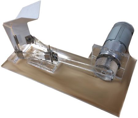
ZULIANI et al.: MINIMALLY ACTUATED TRANSFORMATION OF ORIGAMI MACHINES                                                                                          1427

                                                                                      Fig. 4. The stiffness of each hinge can be varied by changing its total width.
                                                                                      This is done by cutting out inner portions of the hinge.

Fig. 2. The Miura fold pattern. l1 , l2 , and h define lengths of the edges, O, A,    an anti-parallel configuration where θ1 = −θ2 and φ and ψ are
and B identify points on the mechanism, and α is the angle between the spinal
(horizontal) and peripheral creases. Mountain folds are indicated by dashed
                                                                                      functions of θ1 (see Fig. 3). Both configurations are symmetric
lines and valley folds by dotted lines.                                               across the spinal plane.
                                                                                         Each panel has a right-angle trapezoidal shape with a short
                                                                                      horizontal edge of length l1 and a long horizontal edge of length
                                                                                      l2 with a height h as shown in Fig. 2. The angle between the
                                                                                      spinal and peripheral creases is α. Adjacent panels are con-
                                                                                      nected with a 1-DOF rotational hinge. The lengths of our physi-
                                                                                      cal system are h = 25.4 mm, l1 = 40.6 mm, l2 = 60.6 mm, and
                                                                                      α = 45◦.

                                                                                      B. Physical Design
                                                                                         The mechanisms were fabricated using a laminate approach
                                                                                      established in previous origami research [1], [4]. We selected
                                                                                      0.125 mm thick polystyrene sheets for the panels because it is
                                                                                      sufficiently rigid while still being lightweight and machinable
                                                                                      with a laser cutter. We used flexural hinges at each crease
                                                                                      because they are easily fabricated and their stiffness can be
                                                                                      tuned. Several combinations of flexible polymers and glues
                                                                                      were investigated to find the most resilient material with a high
                                                                                      repeatability in operation and fabrication. After experimental
                                                                                      comparisons, we selected standard shipping tape (Scotch Heavy
Fig. 3. Isometric (a) and top (b) views of the Miura fold in a parallel configu-      Duty Shipping Packaging Tape) because the adhesive layer was
ration where θ1 = θ2 are the spinal angles. Isometric (c), top (d), lower isometric   consistent across samples and did not require additional steps
(e), and side (f) views of the Miura fold in an anti-parallel configuration where
θ1 = −θ2 , φ is the angle between the upper and lower spinal hinges, and ψ is
                                                                                      for curing. The tape was applied to one side of the polystyrene
the folded angle of the peripheral hinges.                                            across the gaps between each pair of plates, so that only the tape
                                                                                      connected the plates. The stiffness of these hinges is directly
select the configuration of an origami mechanism through a sin-                       proportional to the width of the flexible joints, so it is easy to
gle open-loop input is a novel capability. We applied this concept                    tune the stiffness of each hinge even after assembly by laser
to a three-finger gripper with a single actuator that is capable of                   machining sections away, as shown in Fig. 4.
precise quasistatic motion and can transform its configuration
to achieve multiple grasping patterns.                                                                             III. MODELING
                                                                                         We start by developing a 2nd-order dynamic model for each
                                  II. DESIGN                                          configuration (parallel and anti-parallel, Fig. 3) from the kine-
A. Origami Design                                                                     matics. We then propose that the system is a hybrid model
                                                                                      that can discretely switch between configurations when pass-
   The elementary component of the system presented here is                           ing through the flat-unfolded state. Finally, we propose that
the Miura vertex. It is an origami pattern made of four plates                        the switching behavior of the hybrid model is determined by
connected by four creases (see Fig. 2) [8], [15]. The Miura                           the system parameters and actuation frequency, resulting in
pattern is well known as a proposed method for deploying satel-                       a repeatable configuration transformation based on the input
lites [9], and has a single kinematic DOF and two possible MV                         frequency.
assignments. The two parallel creases (O A and AB) are the
spinal creases with fold angles θ1 and θ2 and the other two are
the peripheral creases with a folded angle ψ (see Fig. 3). These                      A. Direct Kinematic Model
angles are equal to zero when the mechanism is flat. The Miura                          We first calculate a lumped-parameter dynamic model for
pattern can be folded into either a parallel configuration, de-                       each configuration by solving for the kinematics of each hinge
fined as the configuration where θ1 = θ2 and φ = ψ = 0◦ , or                          and plate with respect to the state variable θ1 . We assume that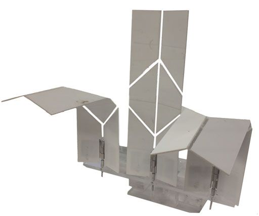
1428                                                                           IEEE ROBOTICS AND AUTOMATION LETTERS, VOL. 3, NO. 3, JULY 2018

the origami structure is an assembly of rigid linkages (the plates)                                  TABLE I
                                                                          TYPICAL SYSTEM PARAMETERS FOR A SINGLE-VERTEX MECHANISM WITH
connected by revolute joints (the hinges), and that the mecha-                        FULL-WIDTH HINGES AND NO ADDED MASS
nism stays in a single configuration. The inertia is derived from
the mass of the plates and the system stiffness is due to the
                                                                                Variable                          Name       Value     Unit
flexural hinges, which act like rotary springs. We then apply the
Euler-Lagrange equations to solve for the equivalent inertia and                Mechanism mass                     m           14       g
                                                                                Flexure thickness                   t          78      μm
stiffness in each configuration.                                                Flexure width                      w            2      mm
   For these models, gravity is neglected. Our interest lies in the             Flexure Young’s modulus             E          1.5     GPa
behavior of the mechanism at or near the flat-unfolded state,                   Spinal stiffness                   kθ         3.0     mN-m
                                                                                Peripheral stiffness               kψ         2.0     mN-m
where the mechanism can switch its configuration. In this state,
                                                                                Spinal inertia                     Iθ         1.5     mg-m2
the mechanism is upright and the effect of gravity is negligible.               Segment inertia                    Iφ         15.9    mg-m2
In addition, we observed that the mechanism does not noticeably                 Anti-parallel natural frequency     fa        2.3      Hz
deflect when oriented in different directions, indicating that the              Parallel natural frequency          fp        7.2      Hz
                                                                                Hybrid natural frequency            fh        3.5      Hz
hinge stiffness is substantially greater than the gravity force.
   1) Parallel Dynamics: In the parallel configuration, the
plates rotate around the spinal hinge [see Fig. 3(a) and (b)].
The inertial moment of each half around the spinal hinge Iθ is a         of the peripheral hinges, then:
function of h and the mechanism mass m. The stiffness kθ of the
spinal hinge is a function of l1 , l2 , the flexure thickness t, width                     l pt3                         l12   3 (l2 − l1 )2
                                                                               kψ = 2E                     Iφ = m            +                      (7)
w, and Young’s modulus E. We solve for kθ by considering the                               12w                           3           2
moment Mh of the flexural hinge as a function of curvature κ                       1                                            1  2
and area moment Ih .                                                            Tθ = (2Iθ ) θ̇12                            Tφ =   Iφ φ̇            (8)
                                                                                   2                                            2
                                                                                 1                                           1  2
                                        lt 3       θ                           Vθ = (2kθ ) θ12                            Vψ =    kψ ψ              (9)
               Mh = E I h κ = E                      = kθ θ       (1)              2                                           2
                                        12         w
                                                                         From the Lagrangian equations we can derive a second-order
                       (l1 + l2 ) t 3                   m h2             model for θ1 .
                kθ = E                             Iθ =           (2)
                           12w                          2 3
                                                                             L = T − V = Tθ + Tφ − Vθ + Vψ                     (10)

Because φ = ψ = 0 at all times, we can derive a second-order                                1  2              1  2
model for θ1 , using the torque τ at the spinal hinge as an input.              = Iθ θ̇12 +    Iφ φ̇ − kθ θ12 +    kψ ψ        (11)
                                                                                            2                   2
                                                                         Solving the Euler-Lagrange equation leads to a lumped mass-
                        τ = 2Iθ θ̈1 + 2kθ θ1                      (3)    spring model. We then linearize this around θ1 = 0 because our
                          = I p θ̈1 + k p θ1                      (4)    interest is in configuration switching, which happens at the flat-
                                                                         unfolded state. If α = 45◦ like in our physical system, we can
                                                                         simplify to a single anti-parallel stiffness ka and anti-parallel
In this way we solve for the parallel stiffness k p and parallel         inertia Ia .
inertia I p .

   2) Anti-Parallel Dynamics: In the anti-parallel configura-                                  ∂φ 2                      ∂ψ 2
tion [see Fig. 3(c)–(f)], the forward kinematics can be derived            τ = 2Iθ + Iφ                θ̈1 + 2kθ + kψ            θ1 (12)
                                                                                               ∂θ1                       ∂θ1
by treating each crease as a vector, as illustrated by Miyashita
et al. [8]. Using this model, we can derive explicit kinematic               = (2Iθ + 4Iφ )θ¨1 + (2kθ + 4kψ )θ1                                    (13)
equations for φ and ψ as functions of θ1 and α.
                                                                             = Ia θ¨1 + ka θ1                                                      (14)

              φ = 2 arctan (sin θ1 tan α)                         (5)    From this we can derive the natural frequencies in the parallel
                                                                       ( f p ) and anti-parallel ( f a ) patterns:
              ψ = arccos sin2 θ1 cos φ − cos2 θ1                  (6)
                                                                                                              1    kp
                                                                                                      fp =                                         (15)
In this configuration the kinetic energy T is the sum of the                                                 2π    Ip
energy Tθ due to the plates rotating around the spine at velocity
θ̇ and the energy Tφ due to the upper segment rotating around                                                 1    ka
the vertex with speed φ̇. The potential energy V is the sum                                           fa =                                         (16)
                                                                                                             2π    Ia
of the energy Vθ due to the displacement of the spinal hinges
θ and the energy Vψ due to the displacement of the peripheral            For a typical structure (full-width hinges for 100% stiffness
hinges ψ. If we consider that Iφ is the inertial moment of the two       and total mass m = 0.014 kg), this results in f a = 2.3 Hz and
upper plates around the z-axis and kψ is the combined stiffness          f p = 7.2 Hz. (see Table I).
ZULIANI et al.: MINIMALLY ACTUATED TRANSFORMATION OF ORIGAMI MACHINES 1429
TABLE II dynamic pattern it will follow. We use the term dynamic pattern
TWO DYNAMIC PATTERNS—PAIRS OF BACKWARD AND FORWARD
CONFIGURATIONS—WERE OBSERVED IN THE SINUSOIDAL ACTUATION OF THE
to refer to the pair of configurations that a mechanism alternates
MIURA MECHANISM between as it oscillates across the flat-unfolded state. In physical
experiments we observed that the mechanisms exhibited one
of two distinct dynamic patterns when driven by a sinusoidal
input. The first (Pattern 1, Table II) consists of the mechanism
alternating between the parallel and anti-parallel configurations
as θ1 crosses the origin. In the second (Pattern 2, Table II), the
mechanism remains in the parallel configuration.
We first considered the possibility that the bifurcation could
be driven by bias in the fold direction of θ2 . However, we
observed that the system would spontaneously enter both
the parallel and anti-parallel configurations in either direction
(Supplemental Video), so we discounted this explanation. Sec-
ond, we considered if the rigid-body dynamics could predict the
configuration. We would expect that in the flat-unfolded state
there would be no spring forces and inertia would dominate the
system. However, if inertia were the only factor, then the con-
figuration would never switch because switching requires the
upper segment (θ2 ) to change directions at the flat position (see
Fig. 5). Therefore, we would never see a hybrid pattern.
Instead we observed that the dynamic pattern (and therefore
the configuration) depended on the actuation frequency. At low
speeds, the upper segment angle θ2 will tend to stay on one
side of the origin (either positive or negative) while the lower
segment switches, resulting in a reliable configuration change
and a hybrid dynamic pattern. At higher frequencies, the kinetic
Fig. 5. Representative values of θ1 (solid line), θ2 (dashed line), and φ (dotted energy of the upper segment is great enough to carry θ2 across
line) in the (a) parallel, (b) anti-parallel, and (c) hybrid dynamic patterns. the origin so that θ2 changes signs every time θ1 does, resulting
in a parallel pattern.
B. Hybrid Model From these observations we propose that the switching fre-
quency shares a similar relationship to the system parameters
The origami mechanism has a kinematic bifurcation point
as the natural frequency — as the stiffness increases, the resis-
when the system is in the flat-unfolded state. This allows for the
tance to change increases, and a higher frequency is necessary
system to switch between configurations as the state variable
to overcome that threshold. As the mass increases, the kinetic
passes through the origin, resulting in three possible dynamic
energy increases, so a lower speed (and frequency) is necessary
patterns: The system can remain in the parallel configuration on
to reach the threshold. Because of these correlations, we pre-
both sides of the origin [which we will refer to as the parallel
dict that the switching frequency is proportional to the natural
dynamic pattern or pattern #2 (see Table II)], remain in the anti-
frequency f switching ∝ f h .
parallel configuration (the anti-parallel dynamic pattern), or it
can switch between the two, so that the configuration is parallel
IV. EXPERIMENTS AND RESULTS
when θ1 > 0 and anti-parallel when θ1 < 0 (or vice versa), and
θ1 and θ̇1 are continuous at θ1 = 0 (see Fig. 5). We refer to this A. Single Vertex Miura Fold
as the hybrid dynamic pattern (or Pattern #1, Table II) because
The experimental tests were performed with a setup ensuring
it can be described with a hybrid dynamic model. In the hybrid
θ1 is actuated symmetrically across the spinal plane (see Fig. 6).
pattern, the system parameters exhibit a discrete change from the
The testing fixture consisted of a motor (Uxcell 12V motor with
parallel to anti-parallel values (or vice-versa) each time θ1 = 0.
gearbox) coupled with a rotary-to-linear mechanism made of
This hybrid system has a natural period ph = p p /2 + pa /2,
acrylic sheets cut with a laser and linked together with acrylic
where p p and pa are the natural periods of the parallel and anti-
glue and aluminum barrel hinges. The input signal is sinusoidal
parallel systems. This results in a natural frequency f h that falls
with an amplitude θ1,max = 30◦ .
between f p and f a . For our example, f h = 3.5 Hz (see Table I).
In our first set of experiments, three mechanisms with differ-
ent hinge stiffnesses (ka = 4.7 mN-m, 9.3 mN-m, or 14 mN-m)
C. Configuration-Switching Model
were actuated by a sinusoidal input with a slowly increasing
These models predict the dynamic behavior of the system frequency (see Fig. 7) from 0 Hz to 4 Hz and the dynamic pat-
assuming we know what dynamic pattern it is following, and tern was recorded as a function of frequency. The results show
therefore what configuration the mechanism will enter from the that there is a frequency threshold at which the dynamic pattern
bifurcation point. However, they do not explicitly predict which changes in a reliable manner, and this threshold depends on the1430 IEEE ROBOTICS AND AUTOMATION LETTERS, VOL. 3, NO. 3, JULY 2018
Fig. 8. Switching frequencies between the two dynamic patterns are plotted as
a function of the anti-parallel stiffness ka of the single vertex Miura mechanism.
Error bars indicate standard deviation, N = 10.
Fig. 6. The experimental mechanisms were driven by an electric motor
through a transmission to sinusoidally fold the spine, resulting in θ1 oscillating
between 30◦ and −30◦ .
Fig. 7. Dynamic Pattern of the Miura mechanism as a function of frequency. Fig. 9. Plot of the switching frequency as a function of the anti-parallel stiff-
The mechanism has a distinct switching frequency that varies with system ness ka . The thin solid lines indicate the switching frequency from experimental
stiffness. The solid line indicates a system with anti-parallel stiffness ka = trials of single mechanisms, and the thick line is their average. The dashed line
4.7 mN-m, the dashed line is a system with ka = 9.3 mN-m, and the dotted line represents the hybrid natural frequency f h .
is a system with ka = 14 mN-m. The patterns are displayed in Table II.
system stiffness. This behavior can be seen in the Supplemental
Video, and the patterns are shown in Table II.
We then built a single mechanism and progressively reduced
the stiffness of its hinges by removing hinge material (see Fig. 4).
In between each stiffness reduction we placed the mechanism
in the flat-unfolded state and applied a frequency sweep while
recording the dynamic pattern. We then identified the switching
frequency as the point when the dynamic pattern changed from a
Pattern #1 to Pattern #2 (see Fig. 8). This was repeated 10 times
for each stiffness. These results indicate that as the stiffness Fig. 10. Plot of the switching frequency as a function of the anti-parallel inertia
increases, the switching frequency increases. Ia . The thin solid lines indicate the switching frequency from experimental
trials of single mechanisms, and the thick line is their average. The dashed line
In order to show repeatability across mechanisms, we per- represents the hybrid natural frequency f h .
formed the same test but with different samples made from
the same design (see Fig. 9) and stiffness values ranging from
16% to 100% of the maximum system stiffness. The switch- We then varied the mass of the upper panels between 14 g
ing frequency from one pattern to the other (see Table II) was to 34 g by adding additional layers to the panels (see Fig. 10).
recorded for four samples with three trials per sample for an The switching frequency from dynamic pattern #1 to #2 was
overall N = 12. These results match our previous observations, recorded for four samples with three trials per sample. These
but indicate that there is noticeable variation between different results indicate that as the system inertia increases, the switching
mechanisms. frequency decreases.ZULIANI et al.: MINIMALLY ACTUATED TRANSFORMATION OF ORIGAMI MACHINES 1431
TABLE III
SIX DYNAMIC PATTERNS WERE OBSERVED DURING SINUSOIDAL ACTUATION
OF THE TWO-VERTEX MECHANISM
Fig. 11. The two-vertex Miura mechanism was used as a finger to design the
origami hand.
In Figs. 9 and 10 we include f h (dashed line), which demon-
strates a proportional relationship with the switching frequency.
In Fig. 9 the hybrid frequency is on average 24% lower than
the switching frequency, indicating that the two frequencies are
proportional but not equal. In Fig. 10 they do match closely;
combined with the previous results, this suggests that there are
other factors affecting the switching frequency that we have not
accounted for.
B. Two-Vertex Miura Fold
We extended this concept to create an origami finger with
two vertices (see Fig. 11). This structure still has a single degree
of freedom but now has four different configurationsb (Supple-
mental Video). To demonstrate that selective transformation of
multiple vertices is possible, we built an origami finger and char-
acterized it through oscillatory inputs. The dynamic patterns we
observed are listed in Table III.
The dynamic pattern was recorded as a function of actuation
frequency in fingers with three different system stiffnesses (see
Fig. 12). The 100% stiff finger predominantly stays in three
different patterns depending on the actuation frequency. The
50% stiff finger exhibits the same general trend but is less pre-
dictable, and at four hertz returns to pattern #4. A third sample
was built with a 100% stiff lower vertex and a 50% stiff upper C. Gripping System
vertex. It demonstrated a more complex behavior but reaches a A gripping system consisting of three origami fingers was
#6 pattern at a slightly lower frequency than the stiffer model built and actuated by a single motor with a rotary-to-linear trans-
and maintains it up to five hertz. mission. The three fingers were built with stiffnesses equal to
The proportion of time the mechanism spent in each dynamic 25%, 50% and 100% of the maximum stiffness (corresponding
pattern was measured as a function of frequency (see Fig. 13). to uncut hinges) in order to obtain a different behavior for each
At each frequency, the mechanism oscillated twenty times and of the fingers at a given actuation frequency. This enables us
the pattern was recorded each period. These results reveal how to selectively transform fingers by applying frequencies which
reliable the pattern is for a given open-loop signal, and the correspond to transformation in one finger but not the others
data indicates that high and low frequency-actuation results in (Supplemental Video).
predictable dynamic patterns, but between 1.5 Hz and 2.5 Hz, Fig. 14 shows the percentage of time each finger spends in
the pattern is not predictable and could end up in three different each dynamic pattern as a function of frequency and shows
patterns. that we can select a configuration of a set of fingers depending1432 IEEE ROBOTICS AND AUTOMATION LETTERS, VOL. 3, NO. 3, JULY 2018
Fig. 14. The likelihood of exhibiting a particular dynamic pattern at each
frequency for three fingers actuated simultaneously with a single actuator. Each
line represents a pattern: Solid line for #2, dashed line for #4, and dotted line
for #6. Top graph is for finger at 100% stiffness, middle is for 50% stiffness,
and bottom is for 25% stiffness.
Fig. 12. Dynamic pattern of a two-vertex mechanism as a function of actuation
frequency with (a) a maximum system stiffness (100%) (b) a reduced upper-
vertex stiffness of 50% and a lower-vertex stiffness of 100%, and (c) an overall
reduced stiffness of 50% at both vertices. (four samples, thick line for the most
likely pattern).
Fig. 15. Different configurations of the three fingers gripping system that are
reached reliably with a respective stiffness of 25%, 50% and 100% for the
fingers from left to right at frequencies of (a) 0.8 Hz (b) 1 Hz (c) 2 Hz and
(d) 3 Hz.
only on the frequency of actuation with a single actuator for
the whole system. Fig. 15 shows the different configurations
reached with different frequencies between 0.8 and 3 Hz in
a reliable manner. These results validate the concept of using
particular frequencies to induce desired configuration changes
in an origami mechanism.
V. DISCUSSIONS AND CONCLUSIONS
Fig. 13. The percentage of time the two-vertex mechanism spent in each
dynamic pattern as a function of frequency, indicating the repeatability at that In this letter we demonstrated that mechanisms can demon-
frequency. Solid line indicates pattern #2, dashed line indicates pattern #4, and strate discretely different dynamic patterns when actuated
dotted line indicates pattern #6. above or below a particular switching frequency, and that thisZULIANI et al.: MINIMALLY ACTUATED TRANSFORMATION OF ORIGAMI MACHINES 1433
can be used to induce a kinematic transformation. Furthermore, [7] H. Shigemune, S. Maeda, Y. Hara, and S. Hashimoto, “Printed paper robot
we showed that the switching frequency is dependent on system driven by electrostatic force,” in Proc. IEEE/RSJ Int. Conf. Intell. Robots
Syst., 2014, pp. 536–541.
parameters and proposed a relationship between switching and [8] S. Miyashita, C. D. Onal, and D. Rus, “Multi-crease self-folding by global
the natural frequency. An origami hand demonstrated that a heating,” Artif. Life, vol. 21, pp. 398-411, 2015.
single actuator can repeatably induce transformation between [9] K. Miura, “Method of packaging and deployment of large membranes
in space,” Ins. Space Astronaut. Sci., Sagamihara, Japan, Rep. 618,
multiple kinematic states. In total, these results indicate that 1985.
origami mechanisms can be tuned through their mass and [10] J. Cai, X. Deng, J. Feng, and Y. Zhou, “Geometric design and mechanical
stiffness to enter specific configurations at specific frequencies, behavior of a deployable cylinder with Miura origami,” Smart Mater.
Struct., vol. 24, no. 12, 2015, Art. no. 125031.
providing a method for controllable transformation through [11] S.-M. Baek, D.-Y. Lee, and K.-J. Cho, “Curved compliant facet
dynamic excitation. origami-based self-deployable gliding wing module for jump-gliding,”
We observed limitations to implementing this transformation in Proc. ASME Int. Des. Eng. Tech. Conf. Comput. Inf. Eng. Conf.,
2016.
in physical systems. If the actuation frequency is mechanically [12] M. Salerno, A. Firouzeh, and J. Paik, “A low profile electromagnetic
programmed via stiffness and mass, it will be coupled to other actuator design and model for an origami parallel platform,” J. Mech.
design parameters. Most notably, with multiple elements that Robot., vol. 9, 2017, Art. no. JMR-16-1214.
[13] D.-Y. Lee, J.-S. Kim, S.-R. Kim, J.-J. Park, and K.-J. Cho, “Design of
are individually controlled, differentiating the vertices requires deformable-wheeled robot based on origami structure with shape memory
that some hinges are a fraction as stiff as others, limiting the alloy coil spring,” in Proc. 10th Int. Conf. Ubiquitous Robots Ambient
stiffness of the entire structure. Future work should address Intell., 2013, pp. 120–120.
[14] S. M. Felton, K. P. Becker, D. M. Aukes, and R. J. Wood, “Self-folding
some way to decouple or mitigate the effect of reduced stiffness with shape memory composites at the millimeter scale,” J. Micromech.
and increased mass on the device operation while still enabling Microeng., vol. 25, no. 8, 2015, Art. no. 085004.
multiple actuation frequencies. [15] A. Firouzeh and J. Paik, “An under-actuated origami gripper with ad-
justable stiffness joints for multiple grasp modes,” Smart Mater. Struct.,
There is also further research necessary to fully model the un- vol. 26, no. 5, pp. 1–10, 2017.
derlying physics of configuration switching. The results indicate [16] X. Sun, S. M. Felton, R. J. Wood, and S. Kim, “Printing angle sensors for
that there are additional parameters besides stiffness and iner- foldable robots,” in Proc. IEEE/RSJ Int. Conf. Intell. Robots Syst., 2015,
pp. 1725–1731.
tia that affect switching frequency. Future dynamic experiments [17] C. Liu and S. M. Felton, “A self-folding robot arm for load-bearing oper-
should include impulse, step, and periodic bang-bang inputs to ations,” in Proc. IEEE/RSJ Int. Conf. Intell. Robots Syst., 2017, pp. 1979–
better characterize the system, and identify how the system con- 1986.
[18] N. M. Benbernou, E. D. Demaine, M. L. Demaine, and A. Ovadya, “Uni-
figuration affects pattern switching. Quasistatic load tests should versal hinge patterns to fold orthogonal shapes,” in Origami5: Proc. 5th
characterize the stiffness of the system as a whole to identify Int. Conf. Origam. Sci., Math. Edu., 2010, pp. 405–420.
coupling between the hinges and plate compliance. The results [19] Z. Abel et al., “Rigid origami vertices: Conditions and forcing sets,” J.
Comput. Geom., vol. 7, no. 1, pp. 171–184, 2016.
also indicate that transformation is not always predictable.This [20] X. Liu, J. M. Gattas, and Y. Chen, “One-DOF superimposed rigid origami
approach could be improved through feedback control, which with multiple states,” Sci. Rep., vol. 6, 2016, Art. no. 36883.
may be able to address the repeatability issues. Finally, these [21] E. D. Demaine and J. ORourke, Geometric Folding Algorithms.
Cambridge, U.K.: Cambridge Univ. Press, 2007.
results should be generalized to other fold patterns in order to [22] J. Cai, X. Deng, Y. Xu, and J. Feng, “Geometry and motion analysis of
establish a unified approach to origami transformation. origami-based deployable shelter structures,” J. Struct. Eng., vol. 141,
no. 10, 2015, Art. no. 06015001.
[23] J. Cai, Z. Qian, C. Jiang, J. Feng, and Y. Xu, “Mobility and kinematic
REFERENCES analysis of foldable plate structures based on rigid origami,” J. Mech.
Robot., vol. 8, no. 6, 2016, Art. no. 064502.
[1] P. S. Sreetharan, J. P. Whitney, M. D. Strauss, and R. J. Wood, “Mono- [24] L. Bowen, B. Trease, M. Frecker, and T. Simpson, “Dynamic modeling
lithic fabrication of millimeter-scale machines,” J. Micromech. Microeng., and analysis of an origami-inspired optical shield for the starshade space-
vol. 22, no. 5, 2012, Art. no. 055027. craft,” in Proc. ASME Conf. Smart Mater., Adapt. Struct. Intell. Syst, 2016,
[2] W. Fischer, G. Caprari, R. Siegwart, I. Thommen, W. Zesch, and R. pp. 1–11.
Moser, “Foldable magnetic wheeled climbing robot for the inspection of [25] S. M. Felton, D.-Y. Lee, K.-J. Cho, and R. J. Wood, “A passive, origami-
gas turbines and similar environments with very narrow access holes,” inspired, continuously variable transmission,” in Proc. Int. Conf. Robot.
Ind. Robot, Int. J., vol. 37, no. 3, pp. 244–249, 2010. Autom., 2014, pp. 2913–2918.
[3] M. Salerno, K. Zhang, A. Menciassi, and J. S. Dai, “A novel 4-DOF [26] J. Cai, X. Deng, Y. Zhou, J. Feng, and Y. Tu, “Bistable behavior of
origami grasper with an SMA-actuation system for minimally inva- the cylindrical origami structure with Kresling pattern,” J. Mech. Des.,
sive surgery,” IEEE Trans. Robot., vol. 32, no. 3, pp. 484–498, Jun. vol. 137, no. 6, 2015, Art. no. 061406.
2016. [27] J. Cai, X. Deng, Y. Zhang, J. Feng, and Y. Zhou, “Folding behavior of a
[4] S. Felton, M. Tolley, E. Demaine, D. Rus, and R. Wood, “A method foldable prismatic mast with Kresling origami pattern,” J. Mech. Robot.,
for building self-folding machines,” Sci. Mag., vol. 345, no. 6197, vol. 8, no. 3, 2016, Art. no. 031004.
pp. 644–646, 2014. [28] J. Cai, Y. Liu, R. Ma, J. Feng, and Y. Zhou, “Nonrigidly foldability analysis
[5] L. Dufour, K. Owen, S. Mintchev, and D. Floreano, “A drone with insect- of Kresling cylindrical origami,” J. Mech. Robot., vol. 9, no. 4, 2017, Art.
inspired folding wings,” IEEE/RSJ Int. Conf. Intell. Robots Syst., 2016, no. 041018.
pp. 1576–1581. [29] N. P. Bende et al., “Geometrically controlled snapping transitions in shells
[6] H. Shigemune, S. Maeda, Y. Hara, N. Hosoya, and S. Hashimoto, with curved creases,” Proc. Nat. Acad. Sci., vol. 112, no. 36, pp. 11175–
“Origami robot: A self-folding paper robot with an electrothermal actuator 11180, 2015.
created by printingorigami robot: A self-folding paper robot with an elec- [30] J. L. Silverberg et al., “Origami structures with a critical transition to
trothermal actuator created by printing,” IEEE/ASME Trans. Mechatron- bistability arising from hidden degrees of freedom,” Nature Mater., vol. 14,
ics, vol. 21, no. 6, pp. 2746–2754, Dec. 2016. no. 4, pp. 389–393, 2015.You can also read