U.S. Postal Service Operating and Maintenance Manual
←
→
Page content transcription
If your browser does not render page correctly, please read the page content below

Operating and Maintenance Manual

   U.S. Postal Service
 PTU-4 Series E-Z Reach
4000 Lb. Capacity Portable Container Tilter

                       Model #: PTU-4

     Serial # _________________________________________

     Placed in Service _________________________________

                 Southworth Products Corp
          P.O. Box 1380 • Portland, ME 04104-1380
        Telephone: 207-878-0700 Fax: 207-797-4734

                                                           November 2008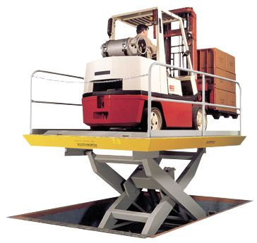
OPERATING AND MAINTENANCE MANUAL

           Southworth Products Corp is widely acknowledged as the leading maker of
           hydraulic lifts and materials-handling equipment. Southworth machines are rugged
           and reliable, and are designed to provide years of trouble-free service. The designs
           are based on extensive engineering experience. These are good reasons for
           specifying Southworth machines in your plant.

2   USPS PTU-4 Owner’s Manual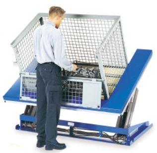
SOUTHWORTH

Contents
INTRODUCTION ............................................................................. Page 4
SAFETY ................................................................................................... 4
INSTALLATION INSTRUCTIONS ............................................................. 5
      Preparation ................................................................................... 5
      Testing .......................................................................................... 5
OPERATING INSTRUCTIONS ................................................................. 6
      Safety labels ................................................................................. 7
      Safety instructions ........................................................................ 8
      Loading the unit ............................................................................ 8
      Raising the tilt platform ................................................................. 9
      Moving the unit............................................................................ 10
      Lowering the tilt platform ............................................................ 10
      Charging the unit ........................................................................ 10
      Precautions for grounding and AC power cord connection .........10
MAINTENANCE ...................................................................................... 11
      Hazards ...................................................................................... 11
      Routine periodic maintenance .................................................... 11
      Hydraulic fluid specifications ...................................................... 12
      Changing the hydraulic fluid ....................................................... 12
      Repacking the cylinder ............................................................... 12
TROUBLESHOOTING ........................................................................... 13
ORDERING REPLACEMENT PARTS ....................................................16
      Recommended Spares ...............................................................16
      Warranty ..................................................................................... 20

List of Figures
Fig. 1                 Labels and Precautionary Markings ........................................ 6
Fig. 2                 Pinch Points ............................................................................ 7
Fig. 3a                Push the unit completely up to the load .................................. 8
Fig. 3b                Place the container up against the tilt platform ........................ 8
Fig. 4                 Correct load center ................................................................. 9
Fig. 5                 Center the load ....................................................................... 9
Fig. 6                 Don’t overfill the container ....................................................... 9
Fig. 7                 Cylinder diagram ................................................................... 13
Fig. 8                 Hydraulic/electric diagram .................................................... 14
Fig. 9                 Hydraulic power unit ............................................................. 17
Fig. 10                Hand control ......................................................................... 17
Fig. 13                Battery schematic ................................................................. 18

                                                                                       USPS PTU-4 Owner’s Manual     3
OPERATING AND MAINTENANCE MANUAL

    Introduction                                           this manual before they install, use, or service
                                                           the unit.
    The Southworth PTU-4 Series “EZ-Reach” Por-            The instructions in this manual are not necessar-
    table Tilter allows staged containers to be picked     ily all-inclusive, as Southworth cannot anticipate
    up, moved into position, and tilted for easy access.   all conceivable or unique situations. In the in-
    Southworth has produced the units described in         terest of safety, please read this whole manual
    this manual for the use of the U.S. Postal Service.    carefully. Please understand the material in
    The PTU-4 units have a maximum capacity of             this manual before you install, use, or service
    4,000 lbs. These are DC-powered units, and have        the E-Z Reach unit. If you have any questions
    an on-board battery (12V unit). Once the battery       about any of the instructions in this manual,
    has been charged, the unit can be operated with-       please contact Southworth Products Corpo-
    out a connection to an outlet. When the battery        ration.
    requires recharging, the 12V unit must be con-         Southworth’s product warranty is shown on the
    nected to a battery charger.                           rear cover of this manual. This instruction manual
    This manual contains instructions on the safe and      is not intended to be or to create any other
    proper installation, use, and maintenance of a         warranty, express or implied, including any
    PTU-4 Series EZ-Reach unit. Be sure that this          implied warranty of merchantability or fitness
    manual is available to the people who install, use,    for a particular purpose, all of which are
    or service the unit. Be sure that all personnel read   hereby expressly excluded. As set forth more

           Safety
           The safety of all persons installing, using, servicing, or working near the EZ-Reach
           unit is of paramount concern to Southworth. The EZ-Reach unit is a powerful
           machine with moving parts, and is capable of causing personal injury if proper
           precautions are not taken.
           Therefore, throughout this manual, Southworth has identified certain hazards which
           may occur in the use of the EZ-Reach unit, and provided appropriate instructions
           or precautions which should be taken to avoid these hazards. In some cases,
           Southworth has also pointed out the consequences which may occur if
           Southworth’s instructions or precautions are not followed. Southworth uses the
           following system of identifying the severity of the hazards associated with its prod-
           ucts:
           DANGER – Immediate hazard which will result in severe personal injury or death.
           WARNING – Hazard or unsafe practice which could result in severe personal in-
           jury or death.
           CAUTION – Hazard or unsafe practice which could result in minor personal injury
           or property damage.
           Please read and follow this instruction manual, including all safety instruc-
           tions and precautions, carefully and completely.

4     USPS PTU-4 Owner’s Manual
SOUTHWORTH
specifically in the product warranty, Southworth’s     7. Check the level of the hydraulic fluid in the
obligation under that warranty is limited to the       tank. In order to check the level, lower the tilt plat-
repair or replacement of defective components,         form completely and unplug the power cord. Re-
which shall be the buyer’s sole remedy, and            move the rear cover on the unit. Open the filler
Southworth shall not be liable for any loss, injury,   cap on the side of the power unit. The fluid should
or damage to persons or property, nor for any di-      reach the elbow in the filler pipe. Do not fill to the
rect, indirect, or consequential damage of any kind    top of the filler pipe – there should always be an
resulting from the EZ-Reach Portable Tilter unit.      air space at the top of the tank.
                                                       8. Be sure the tank vent is not plugged. Before
                                                       operating the unit, you must remove the solid plug
                                                       from the top of the tank and insert the red plastic
Installation Instructions                              vented plug. Also check to be sure the vent line
                                                       is clear.
Preparation
1. Before you start to use the unit, check for lo-
cal codes and ordinances which may apply. It is        Testing
your responsibility to obtain any necessary per-
                                                       1. Be sure the battery is charged. (See page 11.)
mits.                                                  Clear the area around the unit, and warn others to stay
2. Read all of these installation instructions care-   away from the unit.
fully. Be sure to read and understand all of the       2. Operate the unit through its full range of travel.
warnings.                                              The unit should rise smoothly with a quiet humming
                                                       sound, and lower smoothly and quietly. Raise and
3. The unit should only be used indoors, or it         lower the unit a few times to check the lifting action.
should be protected from the weather.
                                                                            WARNING!
                    WARNING!                               As the tilt platform moves up and down,
    • Protect the unit from rain or mois-                  “pinch points” are created at the places
    ture. If the electrical parts in the power             shown in Fig. 2. If you are standing too
                                                           close to the unit when it is moving, your
    unit get wet, workers may be hurt by
                                                           arm or leg may be caught in the moving
    electrical shock. The electrical parts                 parts, and you may be hurt. Stay away from
    may fail if they are wet.                              the pinch points when the unit is moving.
    • This unit has an electric motor                  3. Test the unit with the rated load. If the unit does
    which can create sparks. Don’t use                 not rise, and you hear a loud squealing noise, the pres-
    the unit in an area where flammable                sure relief valve is operating. Contact Southworth for
                                                       instructions.
    gases may be present.
                                                                           WARNING!
4. Remove the shipping material and remove                 Don’t continue to use the unit if this hap-
the unit from the skid. You will need a crane or           pens – the pump will overheat very
lift truck which can lift the unit safely.                 quickly, and may be permanently dam-
                                                           aged. Do not try to adjust the relief valve.
                    CAUTION!
                                                           If you change the setting on the relief
    Do not try to move the lift by support-                valve, you may overwork the unit. This can
    ing the tilt platform. One end of the                  cause the unit to fail suddenly, and you
    tilt platform is free.                                 may be hurt.
5. On the front of this manual, write down the         4. Clean up any spilled hydraulic fluid. Spilled hydrau-
model number, serial number, and date the unit         lic oil is slippery, and may present a fire hazard. If you
                                                       clean up any spilled fluid, you will be able to tell right
is placed in service.
                                                       away if the unit begins to leak.
6. Before using the unit, plug it in and allow the     5. Figure 1a and Fig. 1b show the safety labels on
battery to charge overnight.                           this unit. Check to be sure all of the labels are in place.

                                                                             USPS PTU-4 Owner’s Manual               5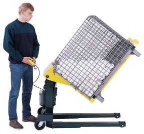
OPERATING AND MAINTENANCE MANUAL

     Fig. 1 Labels and Precautionary
            Markings

6   USPS PTU-4 Owner’s Manual
SOUTHWORTH

  Operating Instructions
  Safety Instructions
                                    WARNING!
      • To avoid bodily injury, please read all instructions before operat-
      ing or servicing the unit.
      • Do not work under the tilt platform when it is raised. Before ser-
      vicing the unit, always lower the unit and unplug the power cord.
      Remember that the battery is still connected, and can still provide
      power to the unit.
      • Never put your hands or feet under the tilt platform.
      • As the unit is operating, stay away from the moving parts shown in
      Fig. 2.
      • Do not stand, sit or ride on the tilt platform.
      • Before raising or lowering the tilt platform, always set the floor
      lock so the unit cannot roll out of position.

Fig. 2 Pinch points

                                                          USPS PTU-4 Owner’s Manual   7
OPERATING AND MAINTENANCE MANUAL

    Loading the unit
    1. Before operating the unit, please read
    and understand all of this section.
    2. Load the unit correctly.
        Before lifting, push the lifting arms of the
    unit completely under the load so that no
    space is left between the load and the tilting
    platform, as shown in Fig. 3a. If you do not
    do this, the container may slide down and
    create dangerous “pinch points.”
        Be sure that the load weighs no more than
                                                                                                             J120
    the maximum rated for the unit. The maxi-
    mum rated load is listed on the data plate.
    Remember that the lifting container may
                                                        Fig. 3a Push the Unit Completely Up to the Load
    weigh 75 lbs. or more.

                      WARNING!
       The tilt platform should always be
       pushed against the load. If the
       load is placed far out on the lifting
       arms, the unit may not be able to
       lift the full rated load safely. See
       Fig. 4. (The unit is designed so
       that the center of load should be
       17" from the bottom of the tilt plat-
       form, and 20" from the face of the
       platform.)

                     WARNING!
       Don’t try to lift a load that exceeds
       the maximum rating. Only lift a load
       if the center of load is within the al-                                                              J121

       lowable range. If you do not follow
       these rules, the unit may fail sud-
       denly. Someone may be hurt, and the              Fig. 3b Before lifting make sure the container is
       unit and load may be damaged.                    pushed up against the tilt platform.

    3. The load should be balanced in the side-
    to-side direction. Whenever possible, place the     4. Sometimes the unit may be used to lift parts
    load in the center of the tilting platform, as      which can roll. If possible, stack the parts in
    shown in Fig. 5. If the load is off-center on the   the parts container so they cannot roll. Do not
    pallet, place the heaviest part of the load near    over-fill the lifting container. See Fig. 6. If the
    the back of the tilt platform – never near the      container is too full, some of the parts may roll
    front!                                              out of the front of the container.

8     USPS PTU-4 Owner’s Manual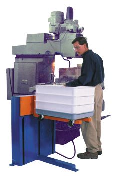
SOUTHWORTH

                                                         the unit in position so that it cannot move acciden-
                                                         tally.
                                                         3. Before lifting, be sure the parts container is
                                                         pushed up against the tilt platform, as shown in
                                                         Fig. 3b. Be sure the load is balanced side-to-side,
                                                         as shown in Fig. 5.
                                                         4. Operate the unit. Press and hold the Up but-
                                                         ton to raise the tilt platform, and Down to lower it.
                                                         If the unit does not operate right away, call a quali-
                                                         fied maintenance worker.
    Fig. 4   Correct Load Center
                                                                            WARNING!
                                                             If you hear a squealing noise from the
Raising the Tilt Platform
                                                             pump, the pressure relief valve is op-
1. Before raising the tilt platform, be sure all work-       erating. Don't continue to use the unit!
ers are clear of the unit.                                   The pump will overheat very quickly,
                  WARNING!                                   and may be permanently damaged.
    As the tilt platform moves up and                        The relief valve is included to protect
    down, “pinch points” are created as                      the machine operators. Do not change
    shown in Fig. 2. Stay away from these                    the setting on the relief valve. If you
    pinch points! Part of your body or                       do change the setting, this may cause
    clothing may become caught, and you                      a hydraulic part to fail. The tilt plat-
    may be hurt. Do not put your hands or                    form may drop suddenly. Someone
    feet under the tilt platform. Do not                     may be hurt, and the unit and load may
    stand or sit on the tilt platform.                       be damaged. The hydraulic parts in
                                                             the unit are designed to handle a cer-
2. Before lifting, set the floor lock. This will keep

                                                                                                         J133
                                              J119

Fig. 5   Center the Load                                  Fig. 6   Don’t Over-Fill the Container

                                                                              USPS PTU-4 Owner’s Manual           9
OPERATING AND MAINTENANCE MANUAL

        tain amount of pressure. The relief                 2. Before lowering the tilt platform, be sure all
        valve has been included for the protec-             workers are clear of the unit.
        tion of all of the workers who use the
        unit.
                                                                             WARNING!
                                                               As the tilt platform moves up and
     Moving the Unit                                           down, “pinch points” are created as
                                                               shown in Fig. 2. Stay away from these
     1. Before moving the unit, always lower the tilt
                                                               pinch points! Part of your body or
     platform to the lowest possible level. You should
                                                               clothing may become caught, and you
     do this even if the unit is not loaded.
                                                               may be hurt.
                       WARNING!
                                                            3. Press the Down button to lower the tilt plat-
        If you try to move the unit while the tilt
                                                            form. The tilt platform should lower at a uniform
        platform is raised more than a few
                                                            speed.
        inches, the unit may be unstable. You
        may be hurt, and the lift or load may
        be damaged.                                         Charging the Unit
     2. Before moving, release the floor lock.              1. The battery power system is designed for in-
     3. Always roll the unit across a stable, solid sur-    termittent duty. The unit is not designed to oper-
     face.                                                  ate continuously. If fully-charged, the battery
                        WARNING!                            should operate the unit for about 30 lift cycles per
        If the floor is not stable or solid, the            charge. The battery should require about 4 hours
        unit may tilt over. You may be hurt,                minimum to recharge completely.
        and the unit or load may be damaged.                2. To begin charging, plug in the 115V power cord
                                                            for the battery charger. A red light on the charger
                                                            indicates charging. A green light will light up when
     Lowering the Tilt Platform                             fully charged.
     1. Before lowering the tilt platform, be sure the
     floor lock is set. This will keep the unit from mov-
     ing accidentally.

                                 PRECAUTIONS FOR GROUNDING
                              AND AC POWER CORD CONNECTION
             Charger should be grounded to reduce risk of electric shock. Charger is
             equipped with an 115V electric cord having an equipment-grounding conduc-
             tor and grounding plug. The plug must be plugged into an outlet that is prop-
             erly installed and grounded in accordance with all local codes and ordinances.

                                                 DANGER
             Never alter the AC cord or plug provided. If it will not fit outlet, have proper
             outlet installed by a qualified electician. Improper connection can result in a
             risk of an electric shock.

10       USPS PTU-4 Owner’s Manual
SOUTHWORTH
Maintenance have been painted over, replace them
before releasing the lift for operation.
All servicing should be done by qualified personnel.
Fig. 1 shows the safety markings on
Qualified personnel should be able to read and un-
this unit.
derstand wiring and hydraulic diagrams. They should
be able to troubleshoot live electrical circuits safely
and in accordance with accepted practice. For Routine Periodic Maintenance
safety's sake, if in doubt, please contact your dealer Every month:
or Southworth Products Corporation Customer Ser-
• Visually inspect the pins and bushings on the
vice Department at (207) 878-0700.
cylinder for signs of wear. Also check the pivot
Before servicing the unit, please read and under- pins at both sides of the tilt platform. If any of
stand all of this section and the section entitled these parts are worn, contact Southworth for re-
“Operating Instructions.” pair instructions.
Hazards • Apply light oil or WD-40 to the parts listed in
There are several hazards you should be aware the last step.
of as you service the unit: Note – Although the bushings are “lifetime lu-
WARNINGS! bricated” Teflon® bushings, their performance may
• As the unit moves up and down, be extended by additional periodic lubrication.
“pinch points” are formed as shown • Check the hydraulic oil level. In order to check
in Fig. 2. Keep hands, feet, and loose the level, lower the tilt platform completely and
clothing away from these pinch points. unplug the power cord. Remove the rear cover
If your hand or arm or a part of your on the unit. Open the filler cap on the side of the
clothing is caught, you may be hurt. power unit. The fluid should reach the elbow in the
• Before performing any maintenance filler pipe. Do not fill to the top of the filler pipe -
on the unit, lower the tilt platform com- there should always be an air space at the top of the
pletely. Failure to do so could result tank.
in severe personal injury. CAUTION!
• The relief valve has been included for It is important to use hydraulic fluid
the protection of all of the workers who with the correct grade and properties.
use the unit. Don't change the relief set- See the hydraulic oil specification in
ting! If the relief valve does not open this section of this manual.
when it should, the unit may fail. Some-
one may be hurt, and the unit and load Every six months or 500 hours of
may be damaged.
operation, whichever comes first:
• If the hydraulic fluid is released un-
• Check all of the hydraulic fittings and hoses,
der high pressure, it can cause per-
and tighten the connections if necessary. Some-
sonal injury. Before you open any part
times the fittings can be worked loose by the vi-
of the hydraulic system, be sure to re-
brations from the power unit.
lease the hydraulic pressure. You can
do this by lowering the tilt platform all WARNING!
the way down. If a hydraulic fitting becomes loose, or
if a hydraulic hose breaks, the hydrau-
• The warning labels have been in-
lic fluid may escape from the system
cluded for the safety of the operator.
under pressure. If the tilt platform is
If the labels are worn or missing, or
USPS PTU-4 Owner’s Manual 11OPERATING AND MAINTENANCE MANUAL
raised when this happens, it can drop Use Texaco type BB or an equivalent.
quickly. Someone may be hurt, or the CAUTION!
unit or load may be damaged. To avoid It is very important to keep the hydrau-
this problem, inspect all of the hydrau- lic oil free of dirt, dust, metal chips,
lic hoses and fittings regularly, and re- water, and other contamination. Most
place them if they are worn or damaged. problems with hydraulic systems are
• The clear plastic vent line and the cylinder rod caused by contamination in the oil.
should be free of hydraulic fluid. If you find much
fluid in either place, the cylinder seals may be leak-
Changing the Hydraulic Fluid
ing. (It is also possible the tank may be over-
filled.) If the worn parts must be replaced, see In order to change the fluid, lower the tilt platform
the section on “Repacking the Cylinder.” completely and remove the rear cover on the unit.
• Disassemble the down valve. Blow the valve To change the fluid, you must remove the power
plunger clean with compressed air. Reassemble unit from the machine. Disconnect the electrical
the valve and reinstall it. wiring, the hydraulic hose, and the vent line. Once
the power unit has been removed, you can re-
• Drain and discard the hydraulic fluid. The suc-
move the filler cap and pour out the old fluid. Fill
tion filter is in the tank, at the point where the suc-
with fresh fluid up to the elbow in the filler pipe.
tion line runs out to the pump. Unscrew the hy-
Do not fill to the top of the filler pipe – there should
draulic line, then remove the filter. Blow the filter
always be an air space at the top of the tank.
clean with compressed air. Reinstall the filter in
the tank and reassemble the hydraulic line. CAUTION!
As you disconnect the hydraulic lines,
• Refill the tank with new hydraulic fluid.
be sure to keep them free of dirt or con-
CAUTION! tamination.
If you continue to use fluid after it has
“worn out,” the moving parts in the
system will wear more quickly.
Repacking the Cylinder
1. Remove the cylinder from the machine. Clean
Hydraulic Fluid Specifications the outside of the cylinder. Push the piston into the
cylinder as far as possible. Drain the oil from the
If the EZ-Reach unit will be used at normal ambi- cylinder. Clear an area near the cylinder so that you
ent temperatures, Southworth supplies the lift with can lay out the parts as you remove them.
Dextron 3 ATF. This may be replaced by any other
2. Secure the cylinder in a vise, or use another
good-quality oil with 150 SSU at 100° F and rust
method to keep it from rotating.
and oxidation inhibitors and anti-wear properties.
3. Using snap ring pliers or a screwdriver, remove
If the EZ-Reach unit will be used at ambient tem-
the snap ring from the gland of the cylinder. Pull the
peratures below 0° F, use aircraft hydraulic oil.
rod out to within 3 to 6 inches of full extension. Com-
The following are equivalent to Dextron 3 ATF: press the ring and, at the same time, pull the rod
TYPE MANUFACTURER and drive the gland out of the cylinder.
D.T.E. 24 MOBIL OIL CO. 4. Carefully remove the rod assembly from the
cylinder and remove the gland. Slip the gland over
NUTO H32 EXXON CO. the end of the rod. Be careful not to damage the
AMOCO AW32 AMOCO CO. finish on the rod.
Citgo AW32 CITGO OIL CO. 5. Carefully examine the seals on the piston and
12 USPS PTU-4 Owner’s ManualSOUTHWORTH
cycles to work out any air bubbles in the hydraulic
fluid.
Troubleshooting
All servicing should be done by qualified person-
nel. Qualified personnel should be able to read
and understand wiring and hydraulic diagrams.
They should be able to troubleshoot live electri-
cal circuits safely and in accordance with accepted
practice. For safety's sake, if in doubt, please
contact Southworth Products Corporation at (207)
878-0700.
Before servicing the unit, read and understand this
entire section and the section entitled “Operating
Instructions.”
Fig. 7
Cylinder Diagram WARNING!
Before performing any maintenance
on this unit, lower the tilt platform com-
gland. Remember the positions of these parts so
pletely.
that you can place the replacement parts correctly.
Notice that the lip on the rod wiper faces upward.
Remove all seals from the piston and gland. o If the tilt platform will not raise:
6. Inspect the parts for damage - nicks, CAUTION!
scratches, cracks, etc. If the platform will not raise, do not
7. Install new seals on the piston and gland. Be continue to hold the Up button for
sure that all parts are free of dirt or contamina- more than 2 or 3 seconds. You may
tion. Install the snap ring on the gland. damage the pump.
8. Coat the inside diameter of the gland with light 1. The battery may need charging. Plug in the
grease and replace it on the rod. unit, and allow the battery to charge overnight.
9. Coat the outside diameter of the piston and 2. The load may be too heavy. Check the actual
seal area on the gland with light grease. Apply a weight of the load. The rated capacity of the unit
light coat of hydraulic oil to the inside diameter of is shown on the name plate. Be sure the center
the cylinder. Insert the rod assembly into the cyl- of the load is within allowable limits. See Fig. 4.
inder. Be careful not to damage the threads, rod, WARNING!
or seals. Don't change the setting of the relief
10. Rotate the gland so that the port for the hy- valve. If you do change the setting,
draulic oil lines up with the hole in the side of the this may cause a hydraulic part to fail.
cylinder. Compress the snap ring and lightly tap The tilt platform may drop suddenly.
the gland into place. Relax the snap ring. Be Someone may be hurt, and the unit and
sure that the snap ring is seated in the groove. load may be damaged. The hydraulic
If the snap ring is not seated, the gland may pop parts in the lift are designed to handle
out of the end of the cylinder under pressure. a certain amount of pressure. The re-
11. Install the cylinder in the machine and test it. lief valve is set to relieve this pressure
Operate the cylinder through several complete before it becomes too great. The re-
lief valve has been included for the
USPS PTU-4 Owner’s Manual 13OPERATING AND MAINTENANCE MANUAL
protection of all of the workers who output voltage, the motor starter relay may be bad.)
use the unit. 5. The tank vent may be plugged. Before oper-
3. The hydraulic oil level may be low. In order to ating the unit, you must remove the solid plug from
check the level, lower the tilt platform completely the top of the tank and insert the red plastic vented
and unplug the power cord. Remove the rear plug. The vent line must be clear.
cover on the unit. Open the filler cap on the side 6. The suction filter may be clogged. Clean the
of the power unit. The fluid should reach the el- suction filter as described in the section on “Peri-
bow in the filler pipe. Do not fill to the top of the odic Maintenance.”
filler pipe – there should always be an air space
at the top of the tank. 7. A vacuum leak may be allowing air into the
suction line, causing cavitation (loss of suction) in
4. The correct voltage may not be reaching the mo- the pump. Check all fittings in the suction line,
tor. In order for the motor to receive power, the motor and tighten or replace them if necessary.
starter relay must be energized. When you press
the Up button, 12V should appear at the small CAUTION!
center terminal of the relay. (If you do not see If cavitation is allowed to continue, the
this voltage, check for a problem with the Up but- pump may be damaged, and may have
ton switch.) to be replaced.
As soon as there is 12V at the center termi- 8. For the tilt platform to raise, the down valve
nal, you should also see 12V at the larger termi- must be de-energized and closed completely.
nal on the left side of the relay. This is the output Check for a problem with the wiring to the down
from the relay to the motor. (If you do not see this
Fig. 8 Hydraulic/Electrical Diagram
14 USPS PTU-4 Owner’s ManualSOUTHWORTH
valve. Check the solenoid in the valve with a volt- o If the unit fails to lower:
meter. The valve must be clean and free to oper- 1. The down valve should be energized and fully
ate. To check this, remove the solenoid and then open. Check the solenoid on the valve with a volt-
the valve. Look for dirt or metal chips which could meter.
block the valve action. Clean the valve plunger
with kerosene, then blow it clean with compressed 2. The valve must be clean and free to operate.
air. The expansion nut which holds the solenoid In order to check the down valve when the tilt plat-
should be finger tight only! form is raised, you must take some special pre-
cautions. Be very careful not to remove the down
valve while the hydraulic system is pressurized.
o If the unit elevates, but fails to hold a load: It can be dangerous to release the pressure sud-
1. The check valve may be leaking. Dirt on the denly.
valve seat can prevent the valve from closing fully. 3. Set the floor lock and block the tilt platform, so
The check valve is located in the pump assem- it cannot possibly move. Next, jack up the tilt plat-
bly, near the center of the power unit. Remove form slightly above its stopping point. This will
the check valve cap and inspect the valve for dirt depressurize the hydraulic system. Now it is safe
or metal chips which may be preventing it from to remove the down valve.
closing. You may be able to restore the seal by 4. Remove the solenoid, then the down valve.
lightly rapping the ball into the seat using a 1/4" Look for dirt or metal chips which could block the
diameter rod and a small hammer. valve action. Clean the valve plunger with kero-
2. The down valve may be energized. While the sene, then blow it clean with compressed air.
unit is holding a load, the down valve should be de- Before reassembly, depress the plunger manu-
energized and fully closed. Check the solenoid in ally several times to be sure it moves freely. The
the valve with a voltmeter. The valve must be clean expansion nut which holds the solenoid should
and free to operate. be finger tight only!
Be very careful not to remove the down valve 5. Once the unit is reassembled, press the Up
while the hydraulic system is pressurized. It can button to take the weight of the tilt platform off of
be dangerous to release the pressure suddenly. the blocks.
Set the floor lock and lower the tilt platform onto
blocks, so it cannot possibly move. Next, jack up If the steps listed above do not solve the problem,
the tilt platform slightly above its stopping point. This please call the Southworth Products Corp Cus-
will de--pressurize the hydraulic system. Now it is tomer Service Department at (207) 878-0700.
safe to remove the down valve.
Remove the solenoid and then the valve. Look
for dirt or metal chips which could block the valve
action. Clean the valve plunger with kerosene,
then blow it clean with compressed air. The ex-
pansion nut which holds the solenoid should be
finger tight only!
3. The cylinder may be leaking. Look for oil on
the cylinder rod and in the vent line. (This may
also occur if the oil tank has been over-filled.) If
you find much oil in either place, and the tank is
not over-filled, the cylinder must be repacked. Turn
to the section on “Repacking the Cylinder.”
USPS PTU-4 Owner’s Manual 15OPERATING AND MAINTENANCE MANUAL
Ordering Replacement Parts
Southworth has carefully chosen the components in your unit to be the best available for the
purpose. Replacement parts should be identical to the original equipment. Southworth will
not be responsible for equipment failures resulting from the use of incorrect replacement
parts or from unauthorized modifications to the machine.
Southworth can supply all replacement parts for your Southworth lift. With your order, please
include the model number and the serial number of the unit. You will find these numbers on
the name plate.
To order replacement parts, please call the Parts Department at (207) 878-0700. Parts are
shipped subject to the following terms:
• FOB factory.
• Returns only with the approval of our parts department.
• Payment net 30 days (except parts covered by warranty).
• Freight collect (except parts covered by warranty).
Parts replaced under warranty are on a “charge-credit” basis. We will invoice you when we
ship the replacement part, then credit you when you return the assumed substandard part.
Parts Department
Southworth Products Corp
P.O. Box 1380
Portland, ME 04104-1380
Telephone: (207) 878-0700
FAX: (207) 797-4734
repairparts@SouthworthProducts.com
Recommended Spares
Item No. Description OEM Part No. Quantity
2989419 Flow Control .......................... Logic ................................... 1
6521262 Cylinder Packing Kit .............. Waltco ................................. 1
3041942P Power Unit 12VDC ................. John S. Barnes .................... 1
1004-021A Front Wheel .......................... Q Wheels ............................ 2
10027653 Rear Wheel ........................... Albion .................................. 2
2997783P Floor Lock ............................. Albion .................................. 1
60016243 Cylinder Assembly ................. Waltco ................................. 1
C141E Battery ................................. AGM/SLA .............................1
10008855 Battery Charger ..................... Guest ...................................1
16 USPS PTU-4 Owner’s ManualSOUTHWORTH
Southworth part no. C-3041942P
Fig. 9
Hydraulic Power Unit
Southworth part no. 3003856
Fig. 10
Hand Control
USPS PTU-4 Owner’s Manual 17OPERATING AND MAINTENANCE MANUAL
Fig. 13
Battery schematic
18 USPS PTU-4 Owner’s ManualSOUTHWORTH
Warranty
Southworth Products Corp warrants its products to be free from defects in material
or workmanship for a period of two (2) years from date of shipment, providing claim is
made in writing within that time period. The structural assemblies (bases, legs, platforms)
are covered under the parts provision of this warranty for an additional three (3) years and
a lifetime warranty on the hydraulic cylinder rod bearings and seals.
This warranty shall not cover failure or defective operation caused by misuse, mis-
application, negligence or accident, exceeding recommended capacities, failure to perform
required maintenance or altering or repairing, unless alteration is authorized by South-
worth Products Corp. Except as set forth herein and including the warranties of merchant-
ability and fitness for the USPS application, there are no other warranties, express or im-
plied.
Southworth Products Corp makes no warranty or representation with respect to the
compliance of any product with state or local safety or product standard codes not men-
tioned in the Contract No: 1CIEQU-04-Q-1541, and any failure to comply with such codes shall
not be considered a defect of material or workmanship under this warranty. Southworth Prod-
ucts Corp shall not be liable for any direct or consequential damages arising out of such noncom-
pliance.
Southworth Products Corp’s obligation under this warranty is limited to the replace-
ment or repair of defective components at its factory or another location at Southworth
Products Corp’s discretion. This is the buyer’s sole remedy. Except as stated herein, South-
worth Products Corp will not be liable for any loss, injury or damage to persons or property,
nor for direct, indirect, or consequential damage of any kind, resulting from failure or defec-
tive operation of said product.
This warranty may be altered only in writing by Southworth Products Corp, Portland, ME.
Southworth Products Corp is widely acknowledged as the leading maker of hydraulic lifts, tilters and other materials
handling equipment. Southworth machines are rugged and reliable, and are designed to provide years of trouble-free
service. The designs are based on extensive engineering experience.
These are good reasons for specifying Southworth machines in your plant.
SOUTHWORTH PRODUCTS CORP
P.O. Box 1380, Portland, ME 04104-1380
Telephone: 800-743-1000 • 207-878-0700
Fax: 207-797-4734
http://blue.usps.gov/purchase/material/pmsc/greensboro
USPS PTU-4 Owner’s Manual 19Southworth is the world class supplier of products designed to improve productivity and
enhance safety. Our staff has over 400 years of engineering experience. If one of our
standard products does not meet your needs, we can design custom equipment
specifically suited to your material handling application.
Spring Loader Lift with Turntable Portable Tilters
Dock Lifts Palletizing Portable Lifts
Stretchwrapping Positioning
Lift & Tilts
Floor to Mezzanine Lifts
For more information, contact Southworth Products
Telephone 800-743-1000 - Fax 207-797-4734
Email: sales@SouthworthProducts.comYou can also read