Service manual 2019 - Faber Fire
←
→
Page content transcription
If your browser does not render page correctly, please read the page content below
Service manual
2019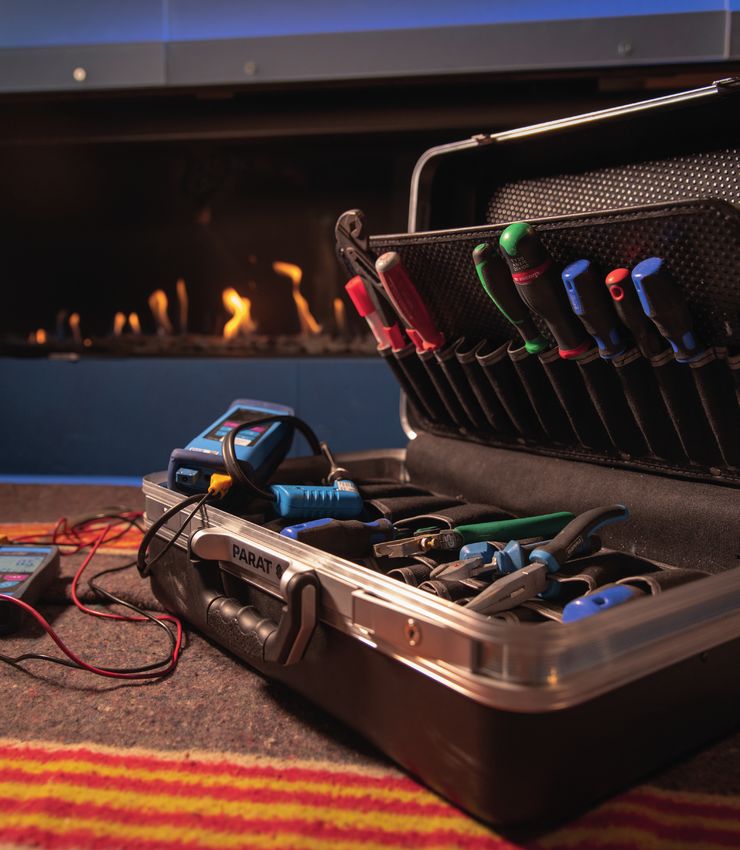
Content

Content................................................................................................................................................................................2
Introduction..........................................................................................................................................................................3
Closed gas fires....................................................................................................................................................................4
Information on the Data badge ...........................................................................................................................................4
Installation............................................................................................................................................................................5
Flue-gas vent and air supply concentric material..................................................................................................................8
Calculate flue configuration, Faber Flue App V2 ..................................................................................................................9
How does the Flue App work................................................................................................................................................9
Flue-gas and air restrictor ..................................................................................................................................................11
Flue configuration...............................................................................................................................................................11
Position of a wall or roof terminal.......................................................................................................................................12
Analyse flue gas CO-CO2 ..................................................................................................................................................13
Fire control.........................................................................................................................................................................15
Control system with ionisation safety.................................................................................................................................15
Pair the remote control.......................................................................................................................................................15
Start procedure and operating principle of an ionisation system.........................................................................................16
Gas control block (Honeywell)............................................................................................................................................17
Control unit (burner controller)...........................................................................................................................................17
Ionisation probe..................................................................................................................................................................18
Control system with a pilot light safety (Mertik)..................................................................................................................19
Pair the remote control with the receiver ...........................................................................................................................19
Gas control block Mertik.....................................................................................................................................................21
Control unit (receivers).......................................................................................................................................................22
Faber ITC App V2...............................................................................................................................................................28
Pair an ITC with an ionisation safety system.......................................................................................................................28
Pair an ITC with a pilot light safety system..........................................................................................................................28
Set the ITC App at dealer level............................................................................................................................................29
App - Menu........................................................................................................................................................................30
Thermostat function...........................................................................................................................................................31
Burner technology in general .............................................................................................................................................32
Maintenance closed gas fires C11 C31 C91 ......................................................................................................................35
Glass maintenance.............................................................................................................................................................38
Fault key for the control system with ionisation safety (Honeywell)....................................................................................39
Fault key for the control system with pilot light safety (Mertik)...........................................................................................40
Explanation of error codes in remote control Symax type B6RBP(T)....................................................................................45

2
Introduction
Notes
The Service Manual provides you with information about
Faber gas fires in general, about dealing with faults and
finding defective components. It is an addition to the
installation manual that is provided with the individual
products. Always read the installation manuals of the fires
carefully.
Who is this manual for? Saturnus 8
The Service Manual is intended for mechanics who fit, carry NL 8448 CC Heerenveen
out maintenance or deal with faults in Faber gas fires. The PO Box 219
requirements for carrying out that work are: NL 8440 AE Heerenveen
• Having attended Faber training courses
• Knowledge of the products
• Knowledge of installing gas fires
• Knowledge of the applicable standards and guidelines
• Having the right tools.
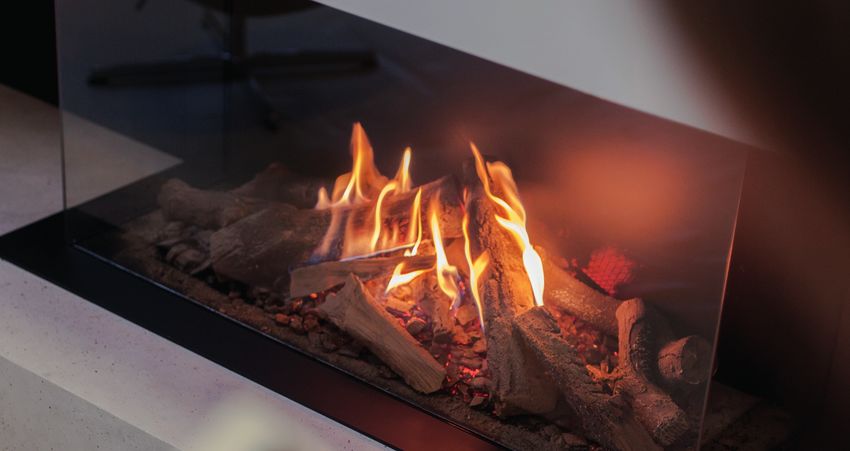
Tools and Electronic support
Faber has modern tools to support consumers and
professionals. They can be downloaded free of charge from
the App Store or Google Play.
Besides these electronic tools, you also use:
• Universal meter
• Gas-pressure meter
• Flue-gas analyzer
Glossary
• Flue configuration chimney
• TVH total vertical height
• THG total horizontal length
• Faber Flue App App that helps you to
calculate the flue configuration
• Ionisation safety control system
• Pilot light safety control system
• Faber ITC App V2 Intelligent Technical Controller –
you use it to operate the fire, but
you can also use it to read
faults and history.
Good luck!
Kind regards,
Marco Bouwmeister
Technical Advisor
3
Balanced flue gas fires

Faber gas fires work on the basis of a closed-system principle known as “Balanced Flue”. A closed fire must use a concentric
pipe to take its combustion air from outside and to discharge its flue gas through the same pipe. It means that the combustion
chamber does not have an open connection with the living area, and there is no danger of carbon-monoxide poisoning.
The concentric duct and the long configurations ensure that this type of fire can fit almost anywhere in the living area.
Outlets can be through the wall, the roof or an existing chimney. Balanced flue fires are noted as C category on the Data
badge.

                             This category means:
                             C11 Horizontal outlet
                             C31 Vertical outlet
                             C91	Fire may be connected to an existing chimney with a flexible stainless steel pipe, and the
                                    remaining clearance operates as combustion air supply

Information on the Data badge

 The serial number of the fire                        #

 Manufacturer's indication number                     PIN

                                                      BE.

 Fire is suitable for the listed countries with the
 corresponding gas type and pressure.

 Outlet through the wall, the roof or an existing Type
 chimney

 Load (input)                                         On Hi

 Voltage                                              V

4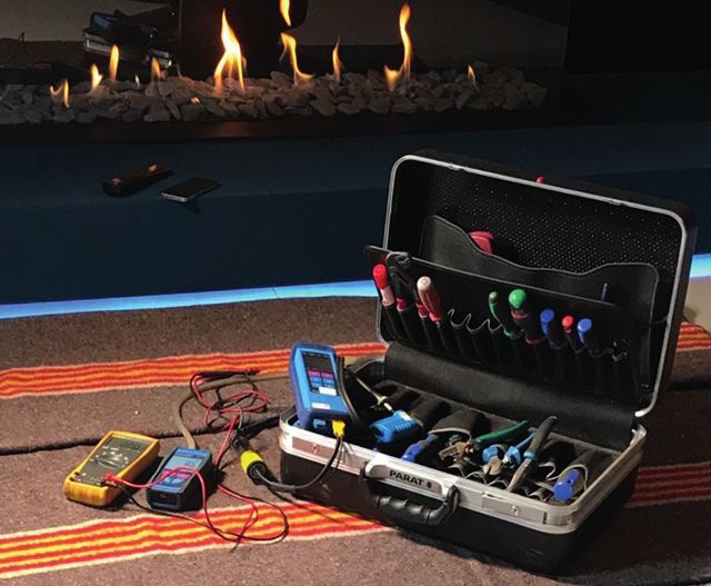
Installation

Stable position of the fire

The fire must be positioned on a stable surface. This could consist of concrete blocks, but Faber also supplies extra long legs
for every type of fire.

Fire-proof environment
The fire must be sited in a refractory existing or false chimney breast. Materials that may be used include: Promatect® or Super
Isol together with metal profiles as corner connection.

To prevent tears in the chimney breast, the chimney breast may not rest on the fire and should be a self-bearing construction.
The fitter will create a bearing construction, if necessary.

Product information
Super Isol
Super Isol is a calcium silicate and it is used as refractory cladding for flues and surrounds. To ensure a proper and sturdy
construction of the chimney breast for an open fire, you can glue your panels first and then screw them onto the metal
profiles.

Characteristic properties of calcium silicate
 • Heat resistant to 1100° Celsius
 • Non-flammable
 • Light-weight
 • Easy to use
 • No dust
 • Easy to fit
 • Extremely durable

Promatect®-H
Promatect®-H consists of calcium silicates, cement and aggregates. Promatect®-H is a stony material. Promatect®-H sheets are
non-flammable and waterproof. Promatect®-H is available in various thicknesses.

Characteristic properties:
 • High mechanical resistance and stability when exposed to fire
 • Heat-resistant
 • Does not rot
 • Waterproof
 • Good chemical resistance
 • Quick and easy to fit
 • Easy to use

Ventilation
The minimum ventilation opening in the chimney breast amounts to 400cm2. Correct ventilation prevents the temperature of
the gas control block and the control becoming too high. It also limits the temperature of the convection air - more ventilation
produces a lower convection temperature.

To guarantee proper access to the control unit you have to use a service hatch.

There should also be at least 1 cm of clearance between the chimney wall and the back of the fire, to ensure a proper heat
discharge behind the fire.

                                           A: Extra ceiling plate in the chimney breast.
                                           B: Mounting frame of the fire.

                                                                                                                                   5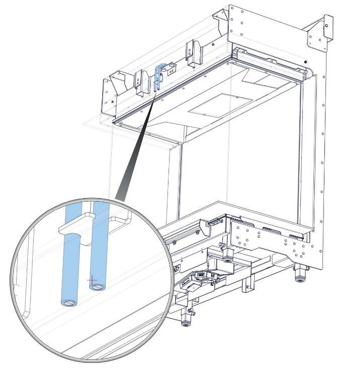
Installation

Flexible pipes gas control block and controls

All the fire's supply pipes need to hang freely below the fire. Pay particular attention to the ignition cable. All cable ties must be
removed and the gas control block and the controls must be properly accessible at all times.

During installation
The gas control block and the electronics must be protected with a plastic bag during installation. Construction dust, plaster,
water and condensation will cause irreparable damage to the control block and the electronics!

Gas connection
Gas connections have to comply with the applicable local standards. For service or maintenance purposes, the gas control
block needs to be fitted with a split connection. A flexible gas connection produces many benefits during servicing.

     !         NB:
               Do not use excessive sealing material (Teflon tape); it may tear the material of the gas control block.

Gas inlet pressure
The correct inlet pressure (standing pressure) is essential to the proper operation of a fire. Always calculate the gas-pipe
diameter - a pressure drop of 2.5 mbar between the gas meter and the fire is permitted. Check the inlet pressure with and
without a load. Always check the gas inlet pressure before you start installing a fire, it saves unpleasant surprises!

     !
              NB:
              For GB and IRL, the home pressure regulator produces a pressure of 20 mbar without a load. If the measured
              pressure has a variance of more than 20% (compared to 20 mbar), you need to report this to the gas company.

Gas valve
The gas valve needs to be fitted in a good, accessible place. The following positions are permitted:

    • Behind the service hatch, on the gas control block

If the gas pipe or the connection does not meet the requirements, the service ingineer needs to report this to the installer.

Electricity connection
Control system with pilot light safety
A Mertik control module works with 4x 1.5 Volt batteries, but if you add ITC and Symbio modules you need a 6 Volt power
adapter.

Control system with ionisation safety
These fires need a 220 Volt electricity supply.

6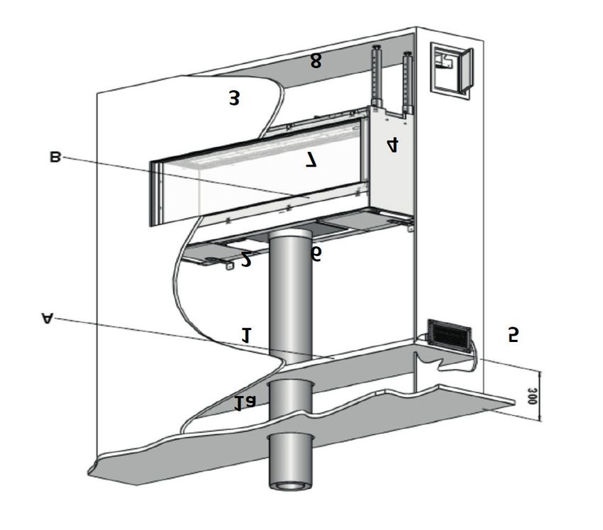
Installation

Flue-gas and air supply concentric material

                       C11                                                    C31              C91

The fire is connected with a concentric pipe system. The outside pipe is the combustion-air intake, the internal pipe deals
with discharging the flue gas. Faber uses two pipe diameters, being 130/200 and 100/150 mm depending on the fire and the
discharge configuration.

System testing
The fire and the duct are tested together and together they have CE testing. Faber uses the following systems:

 • Multi-Vent 		           (manufacturer Mülink and Grol)
 • Multi-Vent Pro          (manufacturer Jeremias)

Only use the flue materials prescribed by Faber; Faber can only guarantee safe and proper operation if those materials are
used.

Calculate flue configuration, Faber Flue App V2
A properly operating system can only be created with a suitable flue configuration that
complies with the restrictions of the fire in question. With the “Faber Flue App V2” it is
simple to calculate whether the flue configuration is possible in combination with your
fire.

How does the Flue App work
The “Faber Flue App V2” provides answers to the following questions:

   1.    Does the flue configuration work for the selected fire?
         Not possible? The app can specify an alternative fire
   2.    Which concentric diameter can I use?
   3.    Where can I reduce the concentric system from 130/200 to 100/150 mm?
   4.    Which flue gas restrictor should I use?
   5.    The blue part of the app provides you with all the important additional information

                                                                                                                              7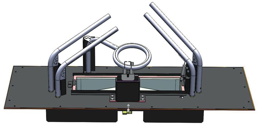
Installation

                                       RESET
                                       INFORMATION
    CURRENT FIRES                      LANGUAGE

                                       NAME OF THE FIRE

                                       START LENGTH

                                       TOTAL VERTICAL FLUE
                                       LENGTH

                                       TOTAL HORIZONTAL FLUE
                                       LENGTH
                                       HORIZONTAL ELBOWS
                                       &
                                       ELBOWS IN THE VERTICAL
                                       PART

                    ABOUT FABER

                    DEALER DATA

                    SAVED CALCULATIONS

                    MAIL CALCULATION

                    HOME/START PAGE

                                         TOTAL HORIZONTAL
                                         PART

                                         ELBOWS IN THE
                                         HORIZONTAL PART

                                         ELBOWS IN THE
                                         VERTICAL PART

                                         FLUE PART BELOW 45
                                         DEGREES

8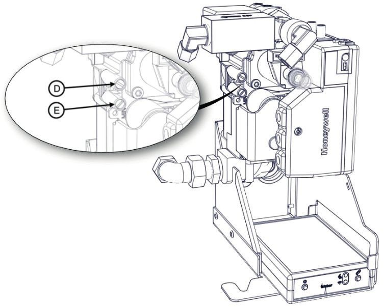
Installation

                                     SELECTED FIRE

                                     SELECTED STL, TVL
                                     AND THL

                                     OUTCOME OF THE
                                     CALCULATION
                                     RED NOT PERMITTED
                                     GREEN PERMITTED

                                     PIPE DIAMETER
                                     DIMENSIONS FLUE-GAS RESTRICTOR

                                     ALL IMPORTANT INFORMATION

                                     STORE AND/OR SEND
                                     DATA BY E-MAIL

  RESET    SET LANGUAGE     HELP           FOR A CALCULATION          FOR A CALCULATION OVER
FUNCTION                  FUNCTION      REGARDING THE CURRENT           ALL FABER FIRES, THE
                                         FIRES, THE BUTTON IS IN       BUTTON IS IN THE ‘OFF’
                                            THE ‘ON’ POSITION                 POSITION

                                                                                                9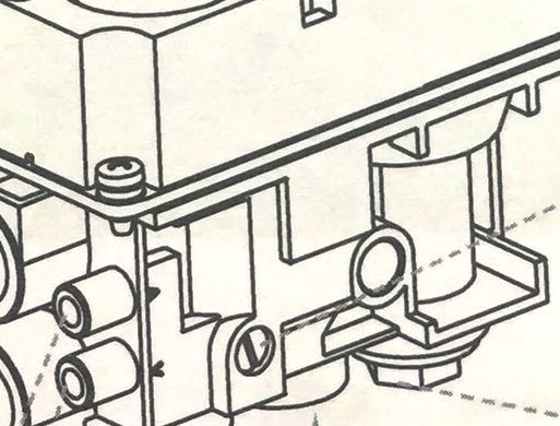
Installation

Flue-gas and air restrictor

The flue-gas and the air restrictor have an important function. They produce the right flame height and the right efficiency.

                                                                                    Position air-restrictor plate
                     Position flue-gas Restrictor

                   at the top of the fire
                                                                                      under in the fire

Flue configuration

We always use a vertical roof terminal in diameter 100/150 mm
See the information that is provided in the blue part of the Flue app.

The horizontal wall terminal is available in a 130/200 and 100/150 mm version
See the information that is provided in the blue part of the Flue app.

10
Installation
Position of a wall or roof terminal
Extension pipe on top of the roof
Discharge limit
The given distances only apply for the proper operation of the fire, for ventilation and nuisance you need to comply with
building regulations.
Position Terminal position Distance mm
A/B/C Come under ventilation and nuisance
D Under a gutter 500
E Under a roofing edge 500
Under a carport or balcony
F 500
in a corner
G Alongside a downpipe 300
H Outside a corner 500
J From wall to wall terminal 1000
K Two wall terminals opposite each other 1000
L Two roof terminals next to each other 450
M Two wall terminals above each other 1000
N Two wall terminals next to each other 1000
11Installation Analyse flue gas CO-CO2 A flue gas analyser can be used to check the combustion gases. There are two measuring points between the glass and the inset frame. The ratio of the CO2 and CO levels may not exceed 1: 100 Example - If CO2 is 4.1%, the max CO is 410ppm If the ratio exceeds 1: 100 or if flue gases are measured in the fresh-air intake. Check the following points: • Terminal blocked • Correct flue-gas restrictor fitted • Internal leak in the concentric material • Horizontal flue length exceeded Position measuring openings 12
Installation

Good to know

Temperature of a concentric tube

     A      Connection      108°

     B         0.5 m        91°

     C         1.5 m        81°

     D          2m          75°

             After the
     E        elbow
                            90°

     F          1m          89°

     G         2.5 m        67°

     H          3m          55°

     I         3.5 m        38°

Temperature in and around the chimney breast

 1A Above the armour        59.7°
    plate of the grids

  1 Immediately below       75.0°
    the armour plate of
    the grids

  2 Middle part of the      91°
    chimney breast

  3 Directly below the      42.8°
    fire

  4 Next to the fire        75°

  5 Convection air          118.8°

  6 Top of the back of      102.9°
    the fire

  7 Middle behind the       107.8°
    fire

  8 Bottom 40 cm below      26.0°
    the fire

                                                         13
Installation
The control of the fire
We have two systems:
• Control over working safely and ignition with ionisation safety (Honeywell)
• Control over working safely and ignition with pilot light safety (Mertik Maxitrol)
Control system with ionisation safety
MAGNETIC VALVE FOR STEP FUNCTION
GAS CONTROL BLOCK
BURNER CONTROLLER
FABER ITC MODULE
Pair the remote control
Press the “pair” button of the Faber ITC controller, until a blue light flashes.
The LED continues to flash blue for as long as the pair mode is activated (60 sec.).
Press button 1 and 5 on the remote control at the same time until the LED starts
flashing blue rapidly and continuously; now release the buttons.
This starts up the pairing process automatically. When the pairing is successful, the
LED light will flash green briefly on the remote control and on the Faber ITC controller.
When pairing fails, the LED on the Faber ITC controller and/or the remote control will
flash red briefly. If this occurs again, repeat the procedure once more and check that
all actions were performed properly and reduce the distance between the remote
control and the Faber ITC controller.
14Operation of the fire
Function buttons on the remote control
1: OFF (top left)
2: ON (top right)
3: Fire down (middle left)
4: Fire up (middle right )
5: Extra burner on/off (bottom left)
6: Glowing embers on/off (bottom right)
All types of remote control work on batteries.
In all types the command signals will be less strong when the batteries are nearly empty.
Replace the batteries once a year to prevent problems.
For the ITC, the need to replace the batteries in the remote control is indicated on time by
the App. You will be given a message on your Smartphone or Tablet.
The thermostat function is built into the remote control. This means that the remote
control needs to be within a 2-metre radius of the fire for the thermostat function to work
well. A wall bracket is supplied for all types of remote control.
Start procedure and operating principle of an ionisation system
The fire is started by means of a set procedure. The burner controller receives a command from the remote control and
releases current to the ignition system and the gas control block. The outflowing gas will be ignited by a powerful spark and the
ionisation probe checks that the outflowing gas actually burns.
It is not possible to give commands during this procedure. This is shown on the remote control with a white flashing LED and
on the ITC App you can see it on the screen. If the user interrupts the start procedure or if the fire does not switch on after the
start procedure, you need to wait for 30 sec before you can start again. The waiting time increases if you make several start-
up attempts. The waiting time is shown on the App.
! NB:
If the fire is switched off during normal use, it is possible to switch it on again after 15 seconds.
15Operation of the fire
Gas control block (Honeywell)
The gas control block has a connection with a 3/8 ISO 7-1 internal thread. The gas control block is operated electronically,
which means that the burner pressure is kept at the correct setting (pressure) by means of voltage.
It is only possible to set burner pressure electronically (in the factory), but you can still check it at any time.
D = Burner pressure measuring
nipple
E = Inlet pressure measuring nipple
Control unit (burner controller)
The burner controller is the control system of the fire. The burner controller operates various components - ignition, ionisation
flow, the flow to the gas control block (flame height).
2 x ignition cable
Ionisation
16Operation of the fire
Ionisation probe
The ionisation probe is positioned above the burner, immediately near a gas-outflow opening. Make sure that the ionisation is
free from any decoration materials and is properly in the flame. Ionisation current is measured in milliampere and expressed in
µA; a good value will be between 4 and 6 µA.
Burner systems with double ignition and ionisation probe
Double ignition pin Ionisation probe
Linear burner
Ionisation probe
Double ignition pin
Log burner 2.0
17Operation of the fire
Control system with a pilot light safety (Mertik)
C
A. Gas control block Mertik
B. Mertik receiver
C. ITC module
B
A
Pair the remote control with the receiver
Standard and Symax remote control;
Press the reset button of the receiver and hold it down until you hear the second long beep. Release the reset button and
press the “flame down” button of the remote control within 20 sec. Two short beeps confirm that the pairing was completed
properly.
18Operation of the fire
Faber ITC controller and remote control
Press Pair on the Faber ITC controller for approximately 5 seconds, until the LED changes from rapid red/green flashing to rapid
green flashing. As long as the LED flashes green (± 1min.) it is possible to pair the remote control.
The pairing is completed by pressing any button on the remote control. The LED flashes green a few times and switches off
when the pairing has been established.
!
NB:
All types of remote control work on batteries. In all types the command signals will be less strong when the
batteries are nearly empty. Replace the batteries once a year to prevent problems.
ITC
The need to replace the batteries in the remote control is indicated on time by the App. You will be given a message on
your Smartphone or Tablet.
The thermostat function is built into the remote control. This means that the remote control needs to be within a 2-metre
radius of the fire for the thermostat function to work well. A wall bracket is supplied for all types of remote control.
Start procedure and operating principles of the pilot light system:
To get gas to the pilot light, the magnetic coil in the gas control block will be opened by putting 4 to 5 mV directly onto the
magnetic coil; this first voltage is supplied by the receiver.
The magnetic coil in the gas control block
opens audibly (CLACK) and gas flows to the
pilot light burner.
At the same time, there is ignition by means
of the ignition pin on the pilot light burner.
(Ignition remains active during the start-up
process)
The gas from the pilot light burner will burn.
The pilot light heats the thermocouple, and
this generates voltage between 12 and max.
20 mV.
After an internal check in the receiver of
approximately 10 sec, a relay switches over in
the receiver audibly (CLICK). Now the voltage
that is generated by the thermocouple will be
Magnetic coil
used to keep the magnetic coil open (ignition
stops). The main burner will be switched on
automatically to maximum capacity.
As long as the voltage is available, the
magnetic coil remains open and the fire will
operate.
19Operation of the fire
Gas control block Mertik
Pilot light adjustment
screw (turn with
screwdriver)
Pressure controller (remove
cap first)
Manual button
Main valve button Connection Piezo ignition
A 2.8 x 0.8 mm
B
Minimum flow opening
Inlet side
Magnetic unit
Outlet side
Inlet bottom
Inlet pressure measuring
point
Outlet pressure measuring
point Outlet top
Technical specifications:
• Maximum inlet pressure, 50mbar (5kPa)
• Mains gas connection: Rp 3/8 ISO 7-1 Internal thread;
• Maximum permitted couple: 35 Nm
• Control block 0°C to max 80°C
20Operation of the fire
Control unit (receivers)
The remote control and the receiver are recognised by the data sticker.
The receivers all have a type number that should match the type number on
the back of the remote control.
If pairing fails, check that the code on the remote control matches the code on
the receiver. A remote control type G6R-H4T2FW and a receiver type B6R-R8U
will not pair! The receiver will give a long beep as an error message.
Receiver type Colour data 1 Thermocouple 2 Thermocouple Remote control 4 8 10
sticker buttons buttons buttons
G6R-R4AU Grey ✔ - ✔ - -
G6R-H4T2FW
G6R-R4AUT Grey - ✔ ✔ - -
B6R-R8U Green ✔ - - ✔ -
B6R-H8TL3W
B6R-R8UT Green - ✔ - ✔ -
B6R-R8P Blue ✔ - - - ✔
B6R-H8TL3PW
B6R-R8PT Blue - ✔ - - ✔
Good to know
The control system automatically switches to the pilot light mode with:
• The standard and Symax remote control: if the flame height was not changed for 3 hours.
• The ITC remote control: Faber ITC App:
Menu/Settings/Energy savings Maximum room temperature 20° to 40°
Or
Menu/Settings/Energy savings Presence detection1 to 24 hours 0°
• Receiver overheats:
If the supply is a 6 Volt adapter, the gas control block switches to pilot light if the temperature exceeds 80°.
If batteries are used as a power supply, the gas control block switches to pilot light if the temperature exceeds 60°.
! NB:
The system switches the pilot light off automatically with:
• A timer function
• When the batteries in the receiver are nearly empty
• On-Demand pilot: If the fire has only been on a pilot light for 5 days, the electronics switch off the pilot light
automatically.
21Operation of the fire Manual start-up of the pilot light Sequence of actions: Switch the ignition cable from the receiver to the connection top left on the gas control block Put button A in the MAN position With a screwdriver you can press down the magnetic valve in the gas control block to ensure a gas flow to the pilot light. By repeatedly pressing the ignition button left below button A, you create a spark that ignites the pilot light. Put button A back to the ON position Manually move button B to the left to turn the fire effect up and to the right to turn the fire effect down or off. The pilot light will stay on. 22
Operation of the fire

Chart

Pilot light burner and pilot light thermocouple

            The flame must be positioned correctly in the thermocouple for proper operation

                                                                                                      23
Operation of the fire
Measurements provide knowledge!
Use the universal meter
Set the meter to mV direct-current voltage.
Thermocouple voltage pilot light side
Measure via the earth and the red wiring cable in the
interrupter.
Red measuring pin to red cable in the interrupter, black
measuring pin to the grounding screw of the gas control
block.
This measurement provides the voltage value over the
thermocouple and will be somewhere between 10 and
12 mV.
+/- 10 to 12 mV
Thermocouple voltage magnetic valve side
Measure via grounding and the black wiring cable in the
interrupter.
Red measuring pin to black cable in the interrupter, black
measuring pin to grounding.
This measurement provides the voltage value over the
magnetic valve and should be at least 4.5 mV.
If the thermocouple circuit is in good condition, it is
possible to measure 6 to 8 mV over black and grounding.
Minimum 4.5 mV
24Operation of the fire
Measure the burner thermocouple, also known as the 2nd thermocouple
After a good start of the pilot light, the main burner will start working, when button B on the gas control block
opens the main burner, the 2nd thermocouple must measure 2 mV within 20 seconds.
Must be measured between black cable to the 5-pin plug and ground within 20 seconds.
How:
When the main burner comes into operation you can measure the value with the black measuring pin on the grounding and the
red measuring pin on the black cable of the 5-pole plug.
A
B
grounding 5-pole plug
2 mV within 20 sec.
If this 2 mV is not achieved within 20 sec, the rotating button B will move back to the Off position and switch off the pilot light.
The fire is switched off and the next start is possible after waiting 2 min. (the receiver will produce 1 beep)
Test the 2nd thermocouple by:
Heating the 2nd thermocouple with a lighter. Is the measured value high enough now? In that case, the thermocouple is
technically in order and the cause needs to be found in:
• Decoration material blocks the flame near the 2nd thermocouple
• Thermocouple is too close to the burner, a distance of 4 mm is sufficient.
25Operation of the fire
Faber Symbio module
Wiring runs via the module connection on the receiver to the Symbio.
The remote control or the App can be used to switch on the Symbio.
Symax version
ITC version
A. 6 Volt power adapter
B. ITC module
C. Mertik receiver
D. Symbio module
E. Gas control block
F. Magnetic valve for the step burner
G. 2nd thermocouple for burner monitoring
! NB:
• Glass pane has a heat-resistant coating (measure resistance function)
• Is there enough ventilation below the fire?
• LED goes off when the ambient temperature exceeds 80°
• When the dimmer function is on maximum, the LED provides no lighting.
• When the fire is switched off, it will still be on that setting when it is switched on again the next time!
26Operation of the fire
Faber ITC V2 APP
With the ITC you have the following options:
• Operation
• Check
• Register
• Advice
• but warnings and maintenance are reported too.
Pair an ITC with an ionisation safety system
• Press the “pair” button of the Faber ITC controller, which is behind the control hatch, until it flashes blue.
• The LED continues to flash blue for as long as the pair mode is activated (60 sec.).
• Press button 1 and 5 on the remote control at the same time until the LED starts flashing blue rapidly and continuously;
now release the buttons (see fig. 1.3).
• This starts up the pairing process automatically. When the pairing is successful, the LED light will flash green briefly on the
remote control and on the Faber ITC controller.
• When pairing fails, the LED on the Faber ITC controller and/or the remote control will flash red briefly. If this occurs, repeat
the procedure once more. Check that all actions were carried out properly and reduce the distance between the remote
control and the Faber ITC controller. After completion of the pairing procedure, the LED light stops flashing blue.
• You can also complete the instructions by using the App. Press the main menu top left and select “Info” and then “Pair
remote control”. LED signals in “power”
Pair an ITC with a pilot light safety system
• Press the pair button B until the LED light moves from flashing red via flashing green to rapid orange flashing. You now
have 1 hour to establish a Wi-Fi connection with the Wi-Fi network by using a smartphone, tablet or computer.
• Establish the connection with the “Faber 0007” Wi-Fi network.
!
NB:
It may take a few minutes before this network becomes visible on your device after pressing the pair
button.
• Press Wi-Fi setting top left on the screen.
• Select your home network and type in the password of your router in the password field.
! NB:
It is only possible to establish a connection with a network that has a password.
If your home network has a hidden name, you should enter the name of the network in the SSID field.
! NB:
Only choose 1 method.
• Now click on connect to establish the connection.
• If this does not happen automatically, you need to restore the connection of your smartphone with your home network
under Wi-Fi settings.
• If the ITC gives a small number of green pulses every 30 seconds after a few minutes, a connection was established.
27Operation of the fire
Set the Faber ITC App V2 at dealer level
By entering the special code, the App can be used at several levels:
• User level - does not require a code
• Dealer level - Faber1844
• Specialists level – a new code is issued annually
The App has a main menu and a sub-menu
You can set the App to dealer level in the following way by using the main menu.
1. Open the App and establish a connection with the
ITC. The connected fire will appear in the App.
To add another fire, press + and complete the
instructions
2. Press “Menu”
3. Press “My Info”
4. Enter your dealer details: Faber1844
5. Press back
6. Press the name of the fire
7. You are now in the sub-menu Press “menu”
8. Scroll down and press “Maintenance”
9. Press “Update maintenance”
10. The next maintenance date is generated
automatically. Confirm with “OK”
28Faber ITC V2 APP
App - Menu
Through “Name of the fire” you obtain all the info about the fire
• Serial number
• Gas type
• Number of kW
• Next maintenance date
With “Settings you have the following settings options
• Fire data
• Ash bed flow effect
• Safety
• Energy savings
• Gas consumption details
• Temperature
• Reset
With “Statistics” you obtain information about consumption and operating hours
• Day
• Week
• Year
Via “Info”
• Pair remote control
• Privacy
Via “Dealer”
• Telephone
• Mail
• Website
Via “Diagnostics” you obtain the following information about the fire
• Diagnostics messages
• Actual measured values
• Version
Via “Maintenance” all the information about
• last and next maintenance date
• Update maintenance date
29Faber ITC V2 APP
Good to know
!
NB:
No temperature display on the App? Press one of the buttons on the remote
control.
Unexpected switch off and automatic switch on again
Twice every 24 hours, the burner controller automatically checks its proper operation. The first
check is after 12 hours, but if the fire is on, this check is skipped. During the second attempt, 12
hours later, the fire is switched off briefly and after the check of the safety system it is switched
on automatically again and put back to the setting it was on before the check.
NB:
!
The fire is switched off if the remote control:
• Is outside the fire's reach
• Is no longer connected to the fire (No remote control connected)
• The batteries are empty
Thermostat function
The default setting for the thermostat function is OFF and the clock thermostat is also on OFF. You can change this in settings
under ‘Thermostat’. It is recommended to switch off both functions if the fire is in a public space and/or is mainly used for
decorative purposes. By switching this function on, the fire may switch on and off at random times.
In the thermostat setting, the Faber ITC controller automatically switches on the additional burner if this is necessary to reach
the required temperature quicker.
The fire is switched off automatically in the thermostat function, if:
• The fire has not been switched on by the thermostat for 8 days.
• The fire has not reached its required temperature after 8 hours at maximum capacity.
• The room temperature, measured by the remote control, exceeds the maximum value set by the user (default 31 degrees).
• The remote control is outside the fire's reach
Reset function
Should the fire become stuck because of a software fault, you can use this function to reset the Faber ITC and burner
controller completely. This is not possible if the fire is blocked for safety reasons by the ITC.
30Faber ITC V2 APP
Good to know
You cannot burn pure gas, you need air too. For full gas combustion you need 2 m3 air for 1 m3 gas. To burn gas we use
“primary air” and “secondary air”. Air is added to the gas in the burner, so that a mixture of gas and air flows from the burner.
This amount of air is known as Primary air. The flame will take the remaining air outside the burner and that is the secondary
air.
Soot formation
An incorrect gas-air mixture may cause soot. Soot should be prevented at all times, because it is simply a sign of incomplete
combustion (CO).
Causes of soot are:
• Dirty fire
• Dirty injector
• Logs placed incorrectly
• Incorrect primary air settings
• Concentric duct not in order (Horizontal length)
31Burner technology - general
Flat Burners
H
E D
F G
Detail A
A Flat Burner needs approximately 15 minutes before the right flame effect is visible.
This type of burner can be decorated with:
• Logs and chips
• Pebbles
• Grey stone
NB:
• Too much decoration material or material that is placed incorrectly will always have a negative impact on the
!
flame effect.
• It is not permitted to use vermiculite granules on the burner, because this produces an enormous amount of
soot.
• The primary air is controlled by two slides on burner F and G, see detail A
• (if the fire is set up for propane gas, the slides are completely open).
Magnetic valve (step function)
All MatriX and Premium fires have a double burner system. By closing the magnetic valve (6V voltage), the burner part E will be
switched off. The magnetic valve is fitted in the gas supply pipe to the switched-on burner.
The magnetic valve needs a voltage impulse of 6 Volt in a millisecond span, which will open or close the valve.
Internal coil = 15 Ohm (I = UxR) I = 6 volt/15 Ohm = 0.4 A for 200 milisec.
A. Gas control block
B. T-piece in the gas supply pipe
C. Magnetic valve
D. Middle burner
E. Step Burner
32Burner technology - general
Log Burner 1.0 and 2.0
The Log Burner produces a realistic camp-fire effect and is quicker in providing the right fire effect quicker than the Flat Burner.
It is important that the logs fit properly over the pipe; broken logs should always be replaced.
This type of burner can be decorated with:
• Logs and chips
Log Burner 1.0
Detail B
! NB:
• Logs that don't fit will provide the wrong flame effect and parts of the burner may become defective
The primary air is a fixed hole in the pipe burner, see detail B.
If the fire is set up for propane gas, there are large primary air holes in the burners. All MatriX fires have double burners. By
closing the magnetic valve (6V voltage), the burner part E will be switched off.
A. Gas control block
B. T-piece in the gas supply pipe
C. Magnetic valve
D. Middle burner
E. Step Burner
F. Pilot light burner
Log Burner 2.0
E E
D
F
33Burner technology - general
Maintenance for balanced flue gas fires C11 C31 C91
Visual inspection
1. Ask whether the fire showed any problems during the past season;
are the log-set instruction chart and the installation manual
available?
2. Check from the ground floor that the terminal is not blocked
3. Check that the glass pane is properly sealed and not broken
4. Check the seal of the overpressure hatches, and the closing of the
overpressure hatches
5. Is there any chimney-breast ventilation?
6. Are the logs positioned in accordance with the instructions?
7. Is there any soot on the logs/pane?
Batteries
Replace the batteries in the remote control. If the fire has pilot light safety and the control/receiver works on batteries, those
batteries should also be replaced.
Cleaning
Clean the convection area, grids and the space below the fire with a vacuum cleaner. The smell of burning dust will be a lot
less.
First brief check
Ignite the fire with the remote control and leave it to work briefly and check the following:
Control with pilot light safety
• Start the pilot light
• Colour and shape of the pilot light (tight and blue)
• Ignite the main burner (must proceed calmly, the rule of thumb is within 3 seconds).
Control with ionisation safety
• Start the fire
• The main burner starts working calmly
• The fire continues to burn
Switch the fire off, the operation of the fire has now been analysed properly.
34Maintenance
When the fire has an ITC:
• Establish a connection with the ITC controller with your own App
• Go to Diagnostics and read the diagnostics messages
• Perform the maintenance by using the following checklist:
Service/maintenance:
Client:
Address:
Postcode:
Tel:
Indication of arrival time
Fire:
Check the fire on the following points. Check
1. Flue
• Check that the concentric duct and the terminal are not blocked.
• Has the correct flue-gas limiter been fitted
2. Gas pipe (Check with a gas-pressure meter)
•C
heck the gas pipe for possible leaks.
(Check the inlet pressure (static pressure); it should be +/- 20 mbar)
Pressure loss in 1 min. =
Tip: leave the gas-pressure meter connected during your maintenance work.
3.a Check control system; Ionisation safety (Honeywell)
• Establish a bluetooth connection with the ITC.
• Go to Diagnostics/ Diagnostics messages/ and read the error codes.
(Diagnostics messages provide clear information about the fire's performance)
• Read the given diagnoses and take action where necessary.
3.b Check the control system; Pilot light safety (Mertik)
• Replace the batteries in the remote control:
•Check the power adapter, does it provide at least 6 Volt?
(If batteries are used, replace the batteries in the receiver.)
35Maintenance
4. The combustion chamber:
• Remove the decoration material from the burner
• Replace or repair broken logs
• Clean the combustion chamber with a vacuum cleaner
• Clean the primary air hole and the burner with a vacuum cleaner
• Check that all the overpressure hatches close/are closed.
• Check the seals of the glass pane
Position decoration material:
• Always position the decoration material in accordance with the instruction chart.
•The ignition pin/pilot light/thermocouples and ionisation probe should be visible and free from
decoration material.
Tip: Too much decoration material or material that is placed incorrectly will have a negative impact
on the fire effect.
Tip: Glow wool may not come into contact with the ignition and the ionisation probe
Tip: S
tart the fire the first time without the glass pane in place to make it easier to make any
adjustments to the decoration material.
5. Cleaning the pane
• Use Faber Polish Glass cleaner, and follow the instructions on the info sheet “glass maintenance”
• Fit the pane.
Tip: Make sure you wear cotton gloves.
6.a Check the operating system; Ionisation safety (Honeywell)
Start the fire with the app and navigate to: Diagnostics/Actual measured values
During the start, pay attention to the following:
• Does the ignition pin produce a clear spark
• Does the main burner ignite calmly.
• Is the ionisation probe positioned properly in the flame
Read the actual measured values:
> Ionisation current
Actual(µA) =
Average (µA) =
(Should produce at least 1.5 µA)
> Modulation valve
Current (mA) =
Burner pressure =
(Compare the burner pressure with the technical data in the installation manual)
> ITC controller
Measured temperature =
(The given temperature is measured in the ITC module)
> Check gas inlet pressure: (read the data of the gas-pressure meter)
Check the inlet pressure (static pressure); it should be +/- 20 mbar.
Inlet pressure no load (+/- 10%) Measured value =
Inlet pressure with load (+/- 10%) Measured value =
36Maintenance
6.b Check the operating system; Pilot light safety (Mertik)
Start the fire with the remote control:
During the start, pay attention to the following:
• The ignition spark is regular and clear
• The pilot light starts with no more than 2 attempts
• The pilot light is tight and blue and touches the thermocouple properly.
• Does the main burner ignite calmly.
Check the thermocouples:
>Thermocouple voltage pilot light side = on the Red interrupter and earthing of the gas
control block
Measured value =
(A good value +/- 12/15 mV)
> Thermocouple voltage magnetic-valve side = on the black interrupter and earthing of the
gas control block
Measured value =
(Minimum 4.5 mVolt)
> Thermocouple voltage, main burner = 5-pole plug and earthing of the gas control block
Measured value =
(1.8 mVolt in 20 sec.)
> Check gas inlet pressure: (read the data of the gas-pressure meter)
Check the inlet pressure (static pressure); it should be +/- 20 mbar
Inlet pressure no load (+/- 10%) Measured value =
Inlet pressure with load (+/- 10%) Measured value =
Tip: When you put the control unit back, make sure the ignition cable is free below the fire and away
from metal parts; the ignition cable should be at least 10 cm away from the aerial on the receiver.
7. Check for gas leaks:
Check the seals of all gas couplings.
8. Flue-gas analysis:
If you have a CO/CO2 flue-gas analyzer, it is possible to check the combustion gases and the supply
air.
There are two measuring pipes for this purpose on the front of the fire between the inset frame
and the glass pane. Leave the fire burn at full capacity for at least 15 min to achieve a correct
measurement.
The CO2 and CO ratio may not exceed 1:100
Example -
CO2 is 4% and CO is 400ppm, measured on high
Tip: too much and incorrectly placed decoration material may produce a high CO value.
Service /maintenance carried out by:
Date:
37Maintenance
Glass maintenance
Cleaning
To ensure long and comfortable enjoyment of your fire, we recommend you use the following
cleaning method.
To prevent damage to coatings, the use of hard scrubbing sponges, abrasive cleaners and
cleaners with ammonia is prohibited. Only use the Faber Glass Polish cleaning product. Only use
microfibre cloths, as supplied.
Finger prints are more visible on anti-reflective glass, so wear cotton gloves when you handle the
pane. If you use suction pads to pick up the pane, remove the pad’s print from the pane.
20714600
Instruction in 4 steps
1. Put sufficient drops of the cleaning product on one of the fibre cloths.
2. Distribute the cleaning product over the pane with the cloth until it has disappeared completely.
!
NB:
Polishing should be done carefully, rub gently and avoid pressure (no squeaking) and be careful
when you remove dirt.
3. Rinse properly with clean water to avoid any cleaning product remaining on the pane.
4. Clean the pane with a second clean, dry fibre cloth.
1st cleaning, immediately after the installation (before trial ignition)
1. The use of methylated spirits is permitted the first time you clean the pane.
2. Remove finger prints and/or stains.
3. Clean the pane with Faber Polish. See instruction 4 steps.
2nd cleaning, after the first time of starting up the fire (for at least 8 hours)
1. Leave the fire to cool down.
2. Clean the pane with Faber Polish. See instruction 4 steps!
3. Clean again if there is a lot of dirt or if you can see dirt.
! NB:
Using copper polish or other cleaning agents may cause irreparable damage to the gas plate!
38Maintenance
Troubleshooting for the control system with ionisation safety (Honeywell)
Establish the connection with the Faber ITC App V2. Select the fire/diagnostics/messages/
actual measured values.
The app will display all faults/messages under diagnostics.
39Maintenance
Troubleshooting for the control system with pilot light safety (Mertik)
Problem Possible cause Solution
A) Receiver produces 1. Batteries in the receiver are empty • Replace the batteries 4x 1.5V AA
three short beeps 2. 6 Volt adapter defective
after every command • Replace the 6 Volt adapter
B) No response when 1. Batteries of the remote control are • Replace the batteries 2x 1.5V AAA or 1x 9V block
the remote control is empty (depending on the type of remote control)
used
2. 6 Volt power adapter defective • Check the 6 Volt power adapter
3. Remote control not paired with the • Pair the remote control with the receiver
receiver • Hold the reset button down until you hear two
beeps. After the second, longer beep, you release
the reset button. Press the low-setting button on
the remote control within 20 sec.
• Two short beeps confirm that the code was set.
C) Receiver does not 1. Receiver defective • Replace the receiver
receive a signal
2. Bent pin connection on the receiver
Tip: also check the wiring on the gas
control block
3. Remote control defective • Replace the remote control
4. No or poor reception • Change the position of the aerial
The receiver is in a metal box!
This disrupts the reception
At least
4 cm
Ignition cable
Aerial
40Maintenance
D) No ignition, no beep 1. Reset the receiver • Press the reset button 1x briefly and the receiver
Receiver does not produces 1 beep.
receive a signal
2. Receiver defective • Replace the receiver
E) No ignition, receiver 1. Loose contact in the thermocouple • Check plug connections and/or repair the wiring.
gives a 5-second circuit/ wiring 2nd thermocouple
long beep
2. Receiver defective • Replace the receiver
3. Magnetic coil defective • Replace gas control block or just the magnetic coil
4. Bent pin connection on the receiver • See C-2
5. Thermocouple broken • Replace thermocouple
F) Ignition stops after 1. Earthing on the gas control block not • Remove the 20 mm Torx screw and clean the
sparking once in order surface properly. Put the Torx screw back and
tighten it properly
41Maintenance
G) No pilot light, but 1. No gas • Check the gas inlet pressure, it should be 25
there is ignition 2. Voltage to open the magnetic valve mbar even when the fire is on maximum. Report a
is insufficient variance of more than 20% to the gas company
• Measure the voltage on the receiver
Tip: put your measuring pin on the
far left pin of the PANEL and the other
on the earthing. The value should be
between 5-6 Volt DC
3. Air in the gas pipe • Vent the gas pipe, can measure inlet pressure via
test point
4. Pilot light blocked • Check pilot light injector
5. Thermocouple wiring incorrect • Check the wiring on the receiver
• Check the wiring on the interrupter
42Maintenance
H) Pilot light goes 1. Not enough voltage on the Put the measuring pins of the multimeter on the
on, but goes out thermocouple or too much earthing and the black cable of the interrupter.
immediately when resistance in the thermocouple This value should be at least 4.5 mV
the main burner circuit
switches on
Min.4.5 mV
2. Gas pressure loss can make the pilot
light too small.
Check and measure the inlet
pressure
Tip: Measure the inlet pressure with
and without load
3. Thermocouple defective • Replace thermocouple
4. Thermocouple position in order?
Tip: always use a new packing gland
when you replace a thermocouple
I) Main burner and pilot 1. 2nd thermocouple not positioned • Change the position of the thermocouple
light go out after 20 properly • Remove the decoration material
sec. 2. Decoration material is blocking • Check the seals of the pane
2nd thermocouple • Check, if possible, if the flue configuration
recommends a flue-gas limiter
J) Pilot light is on, but 1. Button A must be properly in the ON
main burner does not position!
start working
43Maintenance
K) Step Burner does not 1. RESET the receiver Press the reset button briefly and
operate the receiver produces 1 beep.
2. Loose wiring on the receiver Click the plug in the AUX position on the receiver
3. Magnetic valve does not switch • Replace the magnetic valve
Tip: connect a new valve only to the
receiver at first.
Measure:
Internal coil = 15 Ohm
(I= UxR)
I = 6 Volt/15 Ohm= 0.4A for 200milisec.
4. Remote control defective • Check whether the AUX symbol is on the display
when you activate it with your remote control
L) Symbio does not 1. Check the cable connection • Redo the wiring
provide lighting between the receiver and the LED
module.
Tip: check in the Faber ITC App V2
(dealer part) whether the LED is on!
M) No response from 1. Check the Wi-Fi connection
the receiver when
the fire is started Tip: Reset the home router
with a smartphone or
tablet
N) Fire does not respond 1. Remove the wiring from the
via the Domotica Domotica system and start the fire
system manually.
2. Pay attention to the 2nd
thermocouple. If the fire responds
normally, the problem is with the
Domotica
3. If the fire has an ITC, the ITC must
have the Domotica Module
44Explanation of error codes in Symax type B6RBP(T) remote control
Reports that are given on the display of the remote control
Error Reports on the Time on the Description Possible cause
code remote control remote control
F04 F04 4 sec. • No response from receiver • No motor end stop
• No ignition • Motor wiring
• 5 sec. beep from the • Microswitch
receiver • Button B bent
F06 F06 4 sec. • 3rd start-up attempt within 5 • No gas
minutes without success • Air in the pipe
• No spark
F09 F09 4 sec. • No response from the fire • The remote control and the
• No electronic control receiver could not be paired.
F40 Battery symbol Continuous • Battery voltage in remote • Replace batteries
control too low 2x 1.5 V AAA
Contact service
F46 F46 4 sec. • No response from the fire • No or poor connection
• Interrupted responses between the receiver and
• No electronic control the remote control
• No voltage on the receiver
• Low communication reach,
AC adapter.
45Notes: 46
Notes:

         47
Glen Dimplex F. +31(0)513 656501
Consumer Appliances Europe E. info@faber-fires.eu
EU Flame
Saturnus 8 – NL-8448 CC
Heerenveen
PO Box 219 – NL-8440 AE
Proud brand of
Heerenveen
T. +31(0)513 656500 www.faber-fires.euYou can also read