Time-lapse travel time change of multiply scattered acoustic waves
←
→
Page content transcription
If your browser does not render page correctly, please read the page content below
Time-lapse travel time change of multiply scattered
acoustic waves
         Carlos Pacheco
         Center for Wave Phenomena, Department of Geophysics, Colorado School of Mines, Golden,
         Colorado 80401

         Roel Snieder
         Center for Wave Phenomena, Department of Geophysics, Colorado School of Mines, Golden,
         Colorado 80401

         共Received 12 August 2004; revised 6 May 2005; accepted 27 June 2005兲
         Existing techniques in correlation spectroscopy, such as coda wave interferometry and diffusing
         acoustic wave spectroscopy, determine the average motion of scatterers or change in the propagation
         velocity from the temporal change of multiply scattered sound. However, neither of them gives an
         indication of the spatial extent of the change in the medium. This study is an extension of the
         technique coda wave interferometry, where multiply scattered waves are used to determine the
         change in the wave field due to a localized perturbation in the propagation velocity. Here, the
         propagation of multiply scattered sound is described using the diffusion approximation, which
         allows the cross-correlation function of the unperturbed and perturbed wave fields to be related to
         the localized change in the propagation velocity. The technique is tested numerically for
         two-dimensional 共2D兲 acoustic waves using synthetic seismograms calculated using
         finite-differences before and after a small perturbation in the propagation velocity has been
         introduced. Despite the relatively small size and magnitude of the change, multiple scattering
         greatly amplifies small perturbations, making changes in the phase or travel time of the wave field
         visible in the later-arriving waveforms. Potential applications of this technique include
         nondestructive evaluation of inhomogeneous materials and time-lapse monitoring of volcanoes and
         highly heterogeneous reservoirs. © 2005 Acoustical Society of America. 关DOI: 10.1121/1.2000827兴
         PACS number共s兲: 43.20.Fn, 43.28.Lv, 43.40.Ph 关LLT兴                                    Pages: 1300–1310

I. INTRODUCTION                                                       amplitudes and/or travel times from seismic reflection data
                                                                      that have been acquired at two different times. As an ex-
     Most imaging techniques using scattered waves rely on            ample, a 4D dataset recorded at Weyburn Field, Canada, has
the single scattering approximation. Seismic imaging1 mostly          been used to infer time-lapse changes in the oil reservoir
uses primary reflected waves to obtain an image of the sub-           caused by a massive miscible CO2 flood to enhance oil
surface. In many physical problems, however, waves are                recovery.8,9 The main goal of these 4D studies is to extract
strongly scattered and the single scattering approximation is         information about local changes in the reservoir using
not a valid model for the propagation of waves through the            mainly the amplitude information.
medium. In such cases we have to use a model that accounts
                                                                           The fine structure of strongly scattered waves can pro-
for the multiple scattering of waves and the associated at-
                                                                      vide a wealth of new information in seismology, ultrasonics,
tenuation. The diffusion model has been used with success to
                                                                      acoustics, and other fields that study wave propagation in
characterize a wide range of wave phenomena in strongly
                                                                      heterogeneous media.10 Multiple scattering theory has been
scattering media.2–6 In this model, wave energy transport ac-
                                                                      used to determine the number and the scattering strength of
quires a diffusive character, e.g., wave energy is transported
in a process similar to heat diffusion. In medical imaging, for       scatterers in motion inside a highly reflecting cavity, and
example, diffusing near-infrared light has been used to image         more specifically for fish counting in a tank.11,12 In biophys-
localized heterogeneities of tissue.7                                 ics and medical imaging, diffusing photons are now used to
     In many practical applications the medium changes over           view body function and structure after it was found that pho-
time, and therefore the image of the medium changes. We               ton transport within tissues is dominated by scattering rather
then would like to obtain time-lapse measurements in order            than absorption.7 Diffuse transmission spectroscopy13 has
to monitor temporal changes in the medium. Examples of                been used to probe the structure of opaque materials such as
applications where detecting temporal changes may be useful           colloids, foams, and sand, using multiply scattered photons.
include the monitoring of volcanoes, oil reservoirs, radioac-              Multiply scattered waves have also been used to study
tive waste disposal sites, and fluidized suspensions. In reflec-      the dynamics of complex media and turbulent fluids. Diffuse
tion seismology, dynamic reservoir characterization provides          light spectroscopy7 has been used to measure the spatial
optimal management of a reservoir, which leads to increased           variations in the absorption and scattering of large tissue vol-
production. Time-lapse 共4D兲 reflection seismic aims at infer-         umes. Diffusing wave spectroscopy 共DWS兲 is a technique in
ring changes from the medium from changes in the seismic              which multiply scattered light is used to study the dynamics

1300   J. Acoust. Soc. Am. 118 共3兲, Pt. 1, September 2005   0001-4966/2005/118共3兲/1300/11/$22.50   © 2005 Acoustical Society of America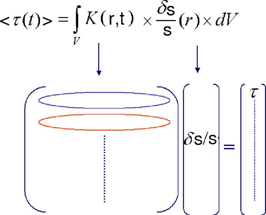
of colloidal suspensions;14 this technique was adapted later
to acoustic waves.15 This technique estimates the average
motion of the scatterers from the temporal fluctuations of
multiply scattered sound. In this technique, the propagation
of multiply scattered sound is described using the diffusion
equation, which makes it possible to relate the temporal field
fluctuations with the dynamics of the multiple scattering me-
dium. Recently, coda waves have been used to study the
temperature dependence of the seismic velocity in granite16
and in a reverberant three-dimensional cavity17 using a tech-
nique called coda wave interferometry. In this technique,
multiply scattered waves are used to detect temporal changes
in a medium by using the scattering medium as an interfer-
ometer. For small changes in the medium, estimates of this
perturbation can be obtained from multiply scattered waves
by a cross correlation in the time domain.16 For larger
changes, the decay of the correlation of the diffuse field is FIG. 1. Actual averaged intensities 共solid line兲 versus best diffusion fit
共dashed line兲 for receivers at 500, 1500, 2500, and 3500 m. The estimated
related to distortion and is an interesting system-dependent value of the diffusion constant is 5.78⫻ 105 m2 / s.
quantity.17 Coda wave interferometry has also been used to
determine the relative location of earthquakes for scattered
amples using finite-difference synthetic seismograms. We
waves.18
found good agreement between our theory and results from
In none of those approaches has an attempt been made
the finite-difference seismograms, despite some fluctuations
to determine the spatial extent of the change or local pertur-
that are analyzed in Sec. VI. Finally, we discuss applications
bation in the medium. When the random multiple scattering
and limitations of the technique in Sec. VII.
medium changes over time, changes in the diffuse field are
related to changes in the medium. The sensitivity to pertur-
II. DIFFUSION ENERGY TRANSPORT AND RANDOM
bations in the medium enhances as the scattering order in- WALKS
creases and thus becomes an interesting tool to detect the
appearance of a very small defect in a multiple scattering The transport of energy through a strongly scattering
sample.19 In this study we develop a technique that relates medium has attracted considerable attention in numerous
the localized changes in the propagation velocity of the me- fields of physics, such as astrophysics, optics, acoustics,
dium to the travel time change of the multiply scattered solid-state physics, and heat conduction. In any of these
waves. As in diffuse wave spectroscopy, this technique relies fields, one studies a pulse of energy that propagates through
on the diffusion approximation of the intensity in strongly the medium with an intensity P共r , t兲. The diffusion equation
scattering media. Therefore, we can model the mean travel describes the propagation of the average intensity in a mul-
time change of waves with propagation time t before and tiple scattering medium.20 In a two-dimensional medium of
after a small and localized change in the propagation velocity infinite extent, constant scattering properties, without intrin-
has been introduced in the medium. This work is an exten- sic attenuation, and in the long-time limit,21 the average in-
sion of coda wave interferometry in the sense that it accounts tensity at r can be approximated by the solution of the dif-
for localized changes in the propagation velocity of the scat- fusion equation
tering medium. Thus, we are able to model the fluctuation in
the phase of the multiply scattered wave field for a given
localized time-lapse velocity perturbation of the multiple
P共r,t兲 =
1
4Dt
exp
4Dt
冋 册
− r2
, 共1兲
scattering medium. We assess the validity of our theory using where r is the distance to the source and D is the diffusion
finite-difference simulations of multiple scattering of acous- constant. Equation 共1兲 describes the temporal evolution of
tic waves in 2D media. the average intensity after the waves have scattered multiple
The paper is divided into five parts. Section II explains times from small-scale heterogeneities. Figure 1 shows the
how the diffusion approximation is used to describe energy average intensity for receivers located 500, 1500, 2500, and
transport in strongly scattering media and its relation with a 3500 m away from the source. The actual mean intensities
random walk process. Section III introduces coda wave in- were calculated after averaging over 100 different receiver
terferometry and how it can be used to obtain an estimator locations after propagating a seismic wave field through a
for the mean travel time change of scattered waves. In Sec. medium with random velocity fluctuations using finite
IV we derive theoretically an expression for the mean travel differences as described in Sec. V. Figure 2 shows one of
time change of multiply scattered waves by using the anal- the seismograms calculated for a source–receiver distance
ogy between a diffusion process and random walks. The of 2500 m. Despite the random appearance of the indi-
main result of this work is the expression that relates the vidual seismogram, an ensemble of such seismograms
mean travel time change of multiply scattered waves with the yields an average intensity that obeys the diffusion equa-
localized perturbation in the propagation velocity of the me- tion. The mean intensities from the finite-difference simu-
dium. In Sec. V we validate the theory with numerical ex- lations are shown as solid curves, whereas the best diffu-
J. Acoust. Soc. Am., Vol. 118, No. 3, Pt. 1, September 2005 C. Pacheco and R. Snieder: Monitoring with multiply scattered waves 1301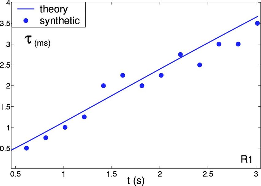
FIG. 2. Example of a finite-difference seismogram for a source–receiver   FIG. 4. Observed distribution of distances for the 5000 realizations of ran-
distance of 2500 m after propagating a finite-bandwidth pulse through a   dom walks 共open circles兲 versus the diffusion curve 共solid line兲 for t = 3 s.
medium with random velocity fluctuations.

                                                                          walk in 2D calculated numerically using D = 3.45
sion fits 关Eq. 共1兲兴 are shown as dashed lines. Notice the
                                                                          ⫻ 105 m2 / s and ve = 5300 m / s. The random walks were cal-
good agreement between the diffusion curves and the av-
                                                                          culated until a maximum elapsed time t = 3 s. If we calculate
erage intensities.
                                                                          many realizations, the distribution of distances r traveled
     Given a seismogram such as the one shown in Fig. 2, it
                                                                          from the origin at a given time t is given by Eq. 共1兲. This is
is extremely difficult to determine if a specific trajectory
                                                                          shown in Fig. 4, were we show the distribution of distances
gives rise to an energy impulse at a specific time t. The
                                                                          traveled for the random walk particles for 5000 different re-
problem is simplified if, instead of considering one specific
                                                                          alizations of random walks starting from the origin with total
trajectory, we consider the average wave field obtained after
                                                                          elapsed time t = 3 s. In Sec. IV we use the random walk
summing the contributions of all possible trajectories arriv-
                                                                          approximation to multiple scattering to derive an expression
ing at the receiver at time t. When scattering is strong and
                                                                          for the mean travel time of waves in a strongly scattering
waves follow infinitely many trajectories, wave propagation
                                                                          medium.
can be considered as a random walk process. This simplifies
the problem because a random walk process can on average
be described with the solution of the diffusion equation. This
provides us with the advantage of a simple physical picture               III. CODA WAVE INTERFEROMETRY
where the diffusively scattered wave field is represented as
the sum of partial waves traveling along various diffuse                       When a strongly scattering medium changes, the speckle
paths.22                                                                  pattern of multiply scattered waves changes, which reflects
     The multiply scattered waves travel through the medium               the changes that occur in the interference of waves traveling
in a random walk process that is characterized in n-D 共where              with different scattering paths through the sample. Multiply
n is the number of dimensions兲 by the transport mean free                 scattered waves are useful in such situations, because they
path l*, the energy velocity ve, and the diffusion coefficient            are increasingly sensitive with time to the perturbations in
D = vel* / n.15 Figure 3 shows three realizations of random               scatterer locations or perturbations in the propagation veloc-
                                                                          ity of the medium. This increased sensitivity is due to the
                                                                          fact that waves bounce more often among scatterers as time
                                                                          increases, and as a result, small changes in the medium are
                                                                          amplified through multiple scattering.
                                                                               For a small perturbation in the propagation velocity, an
                                                                          estimate of this perturbation can be obtained by a time-
                                                                          windowed cross correlation of the unperturbed and perturbed
                                                                          scattered waves.23 The unperturbed wave field uunp共t兲 can be
                                                                          written as a summation of waves over all possible trajecto-
                                                                          ries T24
                                                                               uunp共t兲 = 兺 AT共t兲,                                                  共2兲
                                                                                           T

                                                                          where a trajectory T is defined by the sequence of scatterers
                                                                          that a particular multiple scattering wave encounters, and
                                                                          AT共t兲 is the corresponding waveform. For diffusive wave
FIG. 3. Three realizations of the random walk characterized by D = 3.45   propagation the trajectories T can be thought of as a collec-
⫻ 105 m2 / s and ve = 5300 m / s.                                         tion of random walks.

1302   J. Acoust. Soc. Am., Vol. 118, No. 3, Pt. 1, September 2005        C. Pacheco and R. Snieder: Monitoring with multiply scattered waves
When we introduce a small perturbation of the propaga-
tion velocity, the dominant effect on the multiple scattering
waveform is a travel time perturbation T of the wave that
travels along the trajectory T
uper共t兲 = 兺 AT共t − T兲. 共3兲
T
We can characterize the change in the wave field using the
time-windowed cross-correlation function23
共t,tw兲
Cup 共ts兲 = 冕
t−tw
t+tw
uunp共t⬘兲uper共t⬘ + ts兲dt⬘ , 共4兲
FIG. 5. A random walk particle going from source s at the origin to volume
element dV at r⬘ on time t⬘, and then to receiver at r on time t − t⬘.
where t denotes the center of a time window of length 2tw,
and ts is the lag time for the correlation. When Eqs. 共2兲 and − tw , t + tw兲, the average or mean travel time change 具典 is a
共3兲 are inserted into Eq. 共4兲, double sums 兺TT⬘ appear. We weighted average of the travel time changes of the individual
assume that in these double sums, the cross terms related to trajectories T, i.e.,
different trajectories 共T ⫽ T⬘兲 are incoherent and average out
to zero when the mean of the source signal vanishes. The
contribution of the cross terms is estimated in Ref. 25. A
兺 T I T T
具典 = , 共8兲
dimensionless measure of the change of the wave field is 兺 T IT
given by the time-windowed correlation coefficient, which is
given by
冕 t+tw
where IT is the intensity or probability associated with the
uunp共t⬘兲uper共t⬘ + ts兲dt⬘ trajectory T, which can be calculated using the solution to the
diffusion equation. In the following, we show how to derive
冉冕 冊
共t,tw兲 t−tw
共ts兲 = 共5兲
冕
R t+tw t+tw 1/2 . an expression for this intensity for a given source and re-
2
uunp 共t⬘兲dt⬘ 2
uper 共t⬘兲dt⬘ ceiver location.
t−tw t−tw Let us assume that the seismic energy transport can be
For time shifts ts much smaller than the dominant period described as a diffusion process. Thus, the space and time
of the wave, a second-order Taylor expansion of the AT共t⬘ evolution of the diffusive intensity in the medium due to an
+ ts − T兲 in T gives23 intensity impulse at the origin at time t = 0 is given by P共r , t兲,
as defined in Eq. 共1兲. In multiple scattering of waves, this
R共t,tw兲共ts兲 = 1 − 21
¯ 2具共 − ts兲2典共t,t 兲 ,
w
共6兲 diffusive energy corresponds to the ensemble averaged or
mean intensity 具I典.
where ¯ is the dominant frequency of the wave. In this ex-
We can interpret P共r , t兲 in a different way, regarding
pression 具. . .典共t,tw兲 denotes the average over all waves that
diffusion as a random walk process. In random walk theory,
arrive in the time window 共t − tw , t + tw兲 with a weight factor the product P ⫻ dV represents the probability of a particle on
that is equal to the intensity of the waves.23 Thus, averages a random walk of visiting a volume element dV at location r
are taken with a weight factor that is given by the intensity of at a given time t.26 If, at time t = 0, a normalized intensity
each wave. This means that in this work, the average travel impulse is generated at the source, the total energy within
time change 具典共t,tw兲 is given by an average of the travel time some region V at some later time is given by the integral
change of individual waves with different trajectories T ar-
riving on the time window 共t − tw , t + tw兲, i.e.,
具典共t,t 兲 =
兺T wT共t,tw兲T共t,tw兲
, 共7兲
W共V,t兲 = 冕 V
P共r,t兲dV共r兲. 共9兲
w
兺T wT共t,tw兲
Integration over all space gives the total energy of the sys-
where the weighting factor wT共t , tw兲 is given by the intensity tem, which by the normalization is W共t兲 = 1. The quantity
for the diffuse waves arriving on the time window 共t − tw , t W共V , t兲 is equal to the probability of a particle on a random
+ tw兲. walk of visiting the volume region V at a time t.
We now consider the probability that a random walk
IV. MEAN TRAVEL TIME CHANGE IN THE DIFFUSION particle leaves a source at s at time t = 0, visits a volume
REGIME element dV at r⬘ at time t⬘, and arrives at r at time t as
depicted in Fig. 5. Assuming that the two paths, from source
A. Random walk probabilities
to the volume element, and from the volume element to the
Each random walk from the source to the receiver has an receiver, are independent, this probability is equal to the
associated probability which depends on the diffusion of the product of two probabilities: the probability of the particle of
intensities in the strongly scattering medium. Recalling Eq. going from s to r⬘ in a time t⬘, and the probability of going
共7兲, and considering waves arriving on the time window 共t from r⬘ to r in a time t − t⬘, i.e.,
J. Acoust. Soc. Am., Vol. 118, No. 3, Pt. 1, September 2005 C. Pacheco and R. Snieder: Monitoring with multiply scattered waves 1303P共r⬘,r,s,t⬘,t兲 = P共r⬘,s,t⬘兲P共r,r⬘,t − t⬘兲, 共10兲
where P共r⬘ , r , s , t⬘ , t兲 stands for the probability of all the
trajectories visiting the volume element at location r⬘ at time
t⬘ given that the walk started at the source location s and
ended at the receiver location r at time t.
The probability of a particle to travel from the source to
the receiver is given by the solution to the diffusion equation
for homogeneous medium given in Eq. 共1兲. This solution
also gives the time-dependent intensity P共r , s , t兲 at the re-
ceiver location due to a unit intensity impulse at the source.
This intensity is obtained by summing the contributions to
the intensity of all waves traveling with all possible diffuse
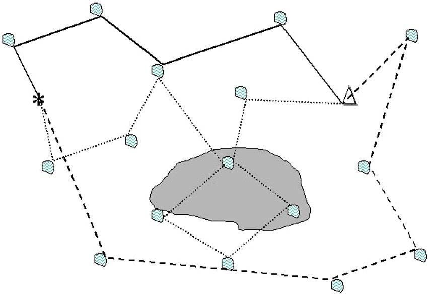
FIG. 6. 共Color online兲 Sensitivity kernel K in 2D for source 共asterisk兲 and
trajectories going from the source to the receiver, i.e., inte-
receiver 共triangle兲 separated 3000 m and t = 2 s. The diffusion constant is
grating Eq. 共10兲 over all possible volume elements dV共r⬘兲 5.8⫻ 105 m2 / s.
P共r,s,t兲 = 冕 V
P共r⬘,r,s,t⬘,t兲dV共r⬘兲
We have obtained in Eq. 共14兲 a representation for the
time t at r in terms of the diffuse intensity due to an impulse
= 冕 V
P共r,r⬘,t − t⬘兲P共r⬘,s,t⬘兲dV共r⬘兲. 共11兲
source at s. The time t corresponds to the time of propagation
of the diffuse intensity. If we define the kernel K共r⬘ , r , s , t兲 as
The integrand P共r⬘ , r , s , t⬘ , t兲 contains the contributions to
the intensity of all paths which are initiated at the source
K共r⬘,r,s,t兲 =
1
P共r,s,t兲
冕0
t
P共r,r⬘,t − t⬘兲P共r⬘,s,t⬘兲dt⬘ ,
location s, visit the location r⬘, and end at the receiver lo- 共15兲
cated at r. By integrating over all the volume where scatter-
ing occurs, we are summing the contributions over all pos- we can express the travel time t as the following volume
sible trajectories from the source to the receiver. Note that in integral:
Eq. 共11兲 no integration over t⬘ is performed. Equation 共11兲 is
a restatement of the Chapman–Kolmogorov equation26 t= 冕V
K共r⬘,r,s,t兲dV共r⬘兲, 共16兲
冕V
P共r,r⬘,t兲P共r⬘,s,t⬘兲dV共r⬘兲 = P共r,s,t + t⬘兲, 共12兲 where K共r⬘ , r , s , t兲 represents the time of flight distribution
of multiply scattered waves started at the source at location s,
visiting location r⬘ and detected on a receiver at location r.
which states that a random walk process starting at t = 0 at Figure 6 shows a plot of the sensitivity kernel calculated for
location s reaches r at t via one of the possible values r⬘ at a a source and receiver separated 3000 m, t = 1 s, and D = 5.8
intermediate time t⬘. ⫻ 105 m2 / s. Note that the kernel vanishes outside the area
The quantity P共r⬘ , s , t⬘兲 in Eq. 共11兲 is the diffuse inten- of an ellipse with foci at the source and receiver location.
sity at a time t⬘ at r⬘ due to an impulse source at s activated
at time t = 0, and P共r , r⬘ , t − t⬘兲 is the intensity at r at time t
due to an impulse source at r⬘ on a time t − t⬘. Equation 共11兲 B. Integral representation for the mean travel time
holds for all times 0 ⬍ t⬘ ⬍ t.26 If we integrate both sides of change of the diffuse wave field
Eq. 共11兲 over time t⬘ over the interval 0 ⬍ t⬘ ⬍ t, we obtain
When the scatterers in a multiple scattering material
tP共r,s,t兲 = 冕冕 V
t
0
P共r,r⬘,t − t⬘兲P共r⬘,s,t⬘兲dt⬘ dV共r⬘兲,
move, or when the propagation velocity of the medium
changes, the diffuse wave field changes. In diffusing acoustic
wave spectroscopy,15 the fluctuations of the multiply scat-
共13兲 tered wave field are measured and analyzed to provide a
sensitive technique for probing the dynamics of the scatter-
where we can identify the time integral 兰t0 P共r , r⬘ , t
ers. Here, we use a similar approach, considering the phase
− t⬘兲P共r⬘ , s , t⬘兲dt⬘ as the time convolution of the two intensi-
changes in the diffuse wave field which arise due to a spa-
ties: one at location r⬘ due to an impulse intensity at s and
tially localized change in the propagation velocity.
the other at location r due to an impulse intensity at r⬘. If we
We perturb the slowness in a finite region of the medium
divide both sides of Eq. 共13兲 by P共r , s , t兲, we arrive at the
as shown in Fig. 7. We work under the assumption that the
following integral representation for the travel time of the
perturbation is weak so that the scattering coefficient does
diffuse wave field:
not change, and the waveform for each scattering path stays
t=
1
P共r,s,t兲
冕冕 V 0
t
P共r,r⬘,t − t⬘兲P共r⬘,s,t⬘兲dt⬘ dV共r⬘兲.
approximately the same. Also, the scattering paths remain
unchanged so that the only difference between the unper-
turbed and the perturbed field is a small travel time pertur-
共14兲 bation, T. If the mean slowness of the medium is denoted by
1304 J. Acoust. Soc. Am., Vol. 118, No. 3, Pt. 1, September 2005 C. Pacheco and R. Snieder: Monitoring with multiply scattered wavesand receiver, an analytical solution for this convolution can
be obtained. In the Appendix we calculate the kernel K for
coincident source and receiver for two- and three-
dimensional media. In 3D, the kernel K is given by
K3D共r,t兲 =
1
2Dr
exp
− r2
Dt
冋 册
. 共20兲
From Eq. 共20兲 we see that the main contributions to the
travel time change come from paths located close to the co-
incident source and receiver location. Also, we can see that
for a fixed distance r the integration kernel K increases with
time t. In multiple scattering, the effective distance traveled
FIG. 7. Multiple scattering paths and a localized perturbation. After the by diffuse waves is proportional to the square root of dis-
perturbation the paths remain the same. The source location is represented tance 共r ⬃ 冑4Dt兲. For smaller value of the diffusion coef-
by an asterisk and the receiver by a triangle. ficient, the stronger the scattering is and the smaller the
effective distance traveled by diffuse waves 共wave paths
s, we calculate the mean length 具L共t兲典 of the multiple scat- become more localized around the source and receiver
tering paths at time t by dividing Eq. 共16兲 by s location兲. Thus, with increased time, diffuse waves sample
the same region multiple times and consequently the
具L共t兲典 = 冕 V
1
s
K共r⬘,t兲dV共r⬘兲, 共17兲
travel time change increases with time.
For the special case of 2D wave propagation the integra-
tion kernel K is for coincident source and receiver 共see the
where we have placed s inside the integral since it is as- Appendix for derivation兲
sumed to be independent of location. For notation simplicity
we have removed the explicit dependence of K on the source
and receiver location. A perturbation in the slowness gives
K2D共r,t兲 =
1
2D
exp
− r2
2Dt
冋 册冋 册
K0
r2
2Dt
, 共21兲
rise to a perturbation in the travel time or phase of the wave where K0 is the modified Bessel function of the second kind.
field, i.e., If we insert Eq. 共21兲 into Eq. 共19兲 and integrate over area
冕 共s + ␦s兲 instead of volume, we obtain
冕 冋 册 冋 册
t + ␦t = K共r⬘,t兲 共r⬘兲dV共r⬘兲, 共18兲
V s 1 − r2 r2 ␦s
具共t兲典 = exp K0 共r兲dA共r兲, 共22兲
2D 2Dt 2Dt s
where ␦s is the perturbation in the background slowness. A
Since in the integral in Eq. 共18兲 we are averaging the contri- where r is the distance from the slowness perturbation
bution to the travel time perturbation of all volume elements, ␦s / s共r兲 element to the coincident source and receiver loca-
␦t becomes the average or mean travel time change that we tion. In Eq. 共22兲, we have obtained an explicit expression
define as 具共t兲典. We have assumed that the perturbation in the relating the mean travel time change 具典 of the diffuse waves
slowness is small 共␦s / s Ⰶ 1兲 so that the travel time perturba- to the localized slowness perturbation 关␦s / s共r兲兴 in a multiple
tion depends only linearly on the slowness perturbation. The scattering medium for coincident source and receiver. In
average or mean travel time change for the multiple scatter- general, for a given perturbation in slowness, we can predict
ing paths with path length L is then the mean travel time change 具典 for any source and receiver
具共t兲典 = 冕
V
K共r⬘,t兲
␦s
s
共r⬘兲dV共r⬘兲, 共19兲
configuration by numerically calculating the convolution in
Eq. 共19兲.
where 具共t兲典 is the mean travel time change of the multiply V. TRAVEL TIME CHANGE FROM FINITE-DIFFERENCE
SYNTHETICS
scattering waves with travel time t and path length 具L共t兲典 due
to the relative slowness perturbation ␦s / s. Note that this av- To generate synthetic seismograms for our study of mul-
erage is weighted by the intensity, since the integration ker- tiple scattering, we use a fourth-order 2D acoustic finite-
nel K共r⬘ , t兲 represents the intensity of diffuse trajectories go- difference code that propagates a finite-duration pulse
ing through location r⬘ with total travel time t, as needed in through a specified velocity field. Following Ref. 27, we
the averaging in Eq. 共8兲. model the 2D velocity field as a constant-background model
To calculate the mean travel time change for a particular with added random velocity fluctuations that constitute the
source and receiver configuration, we need to integrate the scatterers 共see Fig. 8兲. The total velocity field can be decom-
kernel K weighted by the slowness perturbation ␦s / s over posed as
the volume where scattering takes place. The kernel K is
v共r兲 = v0 + vr共r兲, 共23兲
given by the time convolution in Eq. 共15兲. For a source and
receiver at different locations, this time convolution does in where v0 is the background velocity and vr are the random
general not have an analytical solution so it must be evalu- velocity fluctuations. The velocity fluctuations are character-
ated numerically. For the special case of coincident source ized by a Gaussian autocorrelation function with correlation
J. Acoust. Soc. Am., Vol. 118, No. 3, Pt. 1, September 2005 C. Pacheco and R. Snieder: Monitoring with multiply scattered waves 1305FIG. 8. 2D velocity model with random velocity fluctuations added to it.
The correlation length of the velocity fluctuations is 40 m.
FIG. 10. Slowness perturbation added to the initial velocity model to create
the perturbed velocity model. The side length of the square is 3000 m and
distance a, with zero mean and standard deviation 共see Fig. the magnitude of the perturbation is ␦s / s = 0.005. The source is shown as a
star and the receivers as triangles.
8 for a realization of the velocity model兲. The autocorrelation
function of the velocity fluctuations vr has the form
具vr共r⬘兲vr共r + r⬘兲典 = 2 exp 冋 册
− r2
a2
. 共24兲
shown in Fig. 1兲 was obtained by averaging the squared
envelope of all calculated waveforms at a given distance
to the source.
The synthetic seismograms were created by transmitting a We test our theory with the finite-difference simulations
bandlimited pulse with a dominant wavelength of 240 m. of acoustic waves in the multiple scattering regime before
The grid size used was 20 m and the autocorrelation a and after a localized slowness perturbation has been intro-
length was set to 40 m, which is much smaller than the duced in the model. We perturb the random velocity model
wavelength. The mean velocity v0 is equal to 6000 m / s. which represents the unperturbed medium by adding a local-
To ensure strong scattering, we created a velocity field ized slowness perturbation as shown in Fig. 10. The value of
with a relative standard deviation of 25% about the mean the relative slowness perturbation is ␦s / s = 0.005.
velocity value. To test the validity of the diffusion ap- We first analyze the unperturbed and perturbed synthetic
proximation for our numerical model, we performed a nu- seismograms for the receiver R1 located on the perturbed
merical experiment where we placed a source in the region of our model 2000 m away from the source. Figure 11
middle of the model and recorded the seismograms on an shows both the unperturbed and perturbed seismograms for
array of receivers around the source. Figure 9 shows 100 receiver R1. The waveforms consist of diffuse or multiply
synthetic seismograms computed at a distance of 250 m scattered waves that have followed a multitude of paths from
共left兲 and 3000 m 共right兲 from the source. Note the the source to the receiver. Notice the strength of the coda
strength of the multiple scattered arrivals after the highly waves for late times. At first sight there seems to be no
attenuated ballistic arrival, especially for a distance of substantial difference between the wave field before and after
3000 m from the source. The average intensity 共which was the perturbation. However, zooming at around 2 s 共see Fig.
FIG. 9. Seismograms recorded at 250 m 共left兲 and 3000 m 共right兲 from the source.
1306 J. Acoust. Soc. Am., Vol. 118, No. 3, Pt. 1, September 2005 C. Pacheco and R. Snieder: Monitoring with multiply scattered wavesFIG. 11. Unperturbed 共solid兲 and perturbed 共dashed兲 synthetic seismograms
FIG. 13. 共Color online兲 Theoretical versus measured mean travel time
recorded at the receiver R1 located 2000 m away from the source.
change for receiver R1 located 2000 m away from the source.
12兲 we see that the unperturbed seismogram lags in time
change to the relative source and receiver locations with re-
with respect to the perturbed seismogram. More careful in-
spect to the perturbation can be exploited in an inversion
spection indicates that the behavior of the time lags with
scheme to estimate the propagation velocity change from
travel time is systematic, i.e., the lag is increasing with travel
measurements of the mean travel time change at different
time t.
receiver locations. Notice also that for all receivers there are
We calculate the theoretical mean travel time change
fluctuations of the measured travel time change about the
using Eq. 共19兲 for receiver R1 at several propagation times t
theoretical value. We explore the origin of these fluctuations
and compare the result with the mean travel time change
and how to minimize them in the following.
estimated from the synthetic seismograms using the time-
windowed cross-correlation technique. Figure 13 shows
good agreement between the theoretical and the measured VI. FLUCTUATIONS OF THE MEAN TRAVEL TIME
mean travel time change 具典共t兲. CHANGE
We also calculated the mean travel time changes for the We measured the mean travel time change from the syn-
receivers R2 and R3 located 5500 m away from the source. thetic seismograms using a time-windowed cross-correlation
Even though the distance to the source is the same for these technique. The measured mean travel time change measured
receivers, their locations with respect to the perturbation is in this way is approximately an average of the time lags for
different and therefore the mean travel time change is differ- the many scattering events on that time window. The fluc-
ent for the two receivers. The theoretical travel time change tuations seen on the estimated mean travel time change are
for receiver R2 is almost twice the travel time change for due to a number of factors, of which the most important is
receiver R3 共see Fig. 14兲. Also note that we have obtained a the size of the time window. We measure time lags of a
good agreement between the theoretical and estimated mean continuous signal. Special care must be taken not to choose
travel time change. This sensitivity of the mean travel time too small a time window to ensure stability of the estimation
in the time-windowed cross correlation. The larger the time
FIG. 12. Zoom of the unperturbed 共solid curve兲 and perturbed 共dashed
curve兲 synthetic seismograms recorded at the receiver R1 located 2000 m
away from the source. Note the time lags between the unperturbed and FIG. 14. Theoretical versus measured mean travel time change for receivers
perturbed seismograms at different times. R2 and R3 located 5500 m away from the source.
J. Acoust. Soc. Am., Vol. 118, No. 3, Pt. 1, September 2005 C. Pacheco and R. Snieder: Monitoring with multiply scattered waves 1307FIG. 15. Mean travel time change 具典共t兲 estimated from the synthetic seis-
FIG. 16. 共Color online兲 Schematic view of the tomographic problem in
mograms for receiver R1 using different window lengths on the cross cor-
matrix form. The sensitivity kernel K relates linearly the unknown param-
relation. The mean travel time change is in milliseconds. Note the reduction
eters ␦s / s with the measured traveltime change 具典共t兲. Each row in the
in the fluctuations of the measured mean travel time change 共circles兲 around
matrix operator corresponds to a different receiver location.
the theoretical value 共solid line兲 for larger window lengths. The dominant
period is 40 ms. The window length is shown in the upper-left corner of
each plot.
Note that this equation can be used as the basis of a standard
window the more averaging of travel time perturbations oc- linear inverse problem, as there is a linearized relation be-
curs. Thus, choosing a larger window may help minimize the tween the data 共mean travel time change for different times t,
fluctuations of the observed mean travel time change. and different source/receiver pairs兲 and the unknown param-
We can reduce the fluctuations of the estimated mean eters of the medium 共localized slowness perturbation兲 which
travel time change 具典共t兲 by choosing a larger time window we want to retrieve. In the previous section we showed that
length 2tw on the time-windowed cross correlation. Refer- the mean travel time change is a function of time and of the
ence 25 shows that increasing the time window length de- source and receiver locations. This dependence of the mean
creases the magnitude of the cross terms on the average in- travel time change on the relative source and receiver loca-
tensity 具I典, and therefore the fluctuations of the time lags tion with respect to the localized slowness perturbation can
measured in the cross correlation. Larger contributions from be exploited in the inversion scheme for the spatial location
the cross terms to the average intensity imply larger depar- of the slowness change.
tures from the diffusive behavior. We have developed our technique for homogeneous me-
The decrease of the fluctuations with the increase of the dia. In practice, detectors will most likely need to be placed
time window length 2tw can be appreciated in Fig. 15, where on the surface of the medium, so that boundary conditions
we plot the measured mean travel time change 共circles兲 ver- will have to be taken into account. Also, the medium may
sus the theoretical mean travel time change 共solid line兲 using contain layers, so we will have to account for heterogeneity
different window lengths on the time-windowed cross corre- as well. The problem of analyzing the precise effect of a
lation for the receiver R1 of example 1 of the previous sec- contrast of wave velocities and/or scattering strengths be-
tion. We see that the fluctuations of the measured travel time tween them will arise. Under the assumption of an almost
change decrease with increasing window length 2tw. For this isotropic scattering field28 we determined the boundary con-
synthetic example, the dominant period Tdom is 40 ms. The ditions for the diffusion and radiative transfer equations for
length of the time window in Fig. 15 varies from layered media. Undoubtedly all this will make our kernels
70 to 420 ms. more complicated.
Future work includes developing an inversion scheme to
obtain the shape and magnitude of the slowness perturbation
VII. CONCLUSIONS
from the measured travel time changes at different receiver
We have developed a technique that relates the mean locations. This is similar to the transmission tomography
travel time changes to the local changes in the propagation problem, with the added complication that we are not only
velocity of the medium. The theory is formulated by means taking first or minimum time arrival but all multiple arrivals
of the diffusion approximation of the multiple scattering due to the interference of multiply scattered waves. The
wave field. The sensitivity kernel K共r , t兲 describes the depen- problem is simplified due to the fact that we are not using
dence of the mean travel time change with the source and explicitly the paths as in transmission tomography but rather
receiver location, the relative slowness perturbation, and the using the average wave field obtained with the diffusion ap-
diffusion constant of the medium. proximation. Instead of calculating the travel time change
Equation 共19兲 relates the mean travel time change 具典 with infinitely many line integrals, we calculate the mean
⫻共t兲 at time t with a localized slowness perturbation ␦s / s共r兲. travel time change using a much simpler volume integral that
1308 J. Acoust. Soc. Am., Vol. 118, No. 3, Pt. 1, September 2005 C. Pacheco and R. Snieder: Monitoring with multiply scattered wavescontains the contributions of all possible paths. For a given 2 关−r2/t兴
冕 ⬁
e −d
冑
time t and for a fixed source location we can set up the P共r,t兲 = 2e . 共A6兲
共4D兲 0 r2
inverse problem in matrix form using different receivers as is +
2
shown in Fig. 16. The matrix operator 共calculated from the Dt
time of flight distribution K兲 which multiplies the unknown This integral can be calculated identifying it as a integral
parameter vector 关slowness perturbation ␦s / s共r兲 as a func- of the type
tion of position兴 generates the data 共mean travel time change
for different receiver locations兲. Each row in the matrix cor-
responds to an observation of mean travel time change for a
冕冑0
⬁
e−pxdx
x共x + a兲
= eap/2K0 冉 冊 ap
2
, 共A7兲
specific source–receiver pair at a discrete number of times t.
This technique can be used to detect temporal changes in for a ⬎ 0 and p ⬎ 0. The solution to the integral in Eq. 共A7兲
highly heterogeneous material or reservoirs given that the can be found in Ref. 29. Setting p = 1 and a = r2 / Dt, expres-
diffusion approximation of the intensities is valid. sion 共A7兲 becomes
ACKNOWLEDGMENTS
共P ⴱ P兲共r,t兲 =
2
共4D兲2t
exp
− r2
2Dt
K 0冋 册冋 册
r2
2Dt
, 共A8兲
where K0 is the modified Bessel function of the second kind.
This work was supported by the Consortium Project on Substituting Eqs. 共A4兲 and 共A2兲 into Eq. 共A1兲, we arrive at
Seismic Inverse Methods for Complex Structures at the Cen- the expression for the kernel K共r , t兲 in two dimensions for
ter for Wave Phenomena. We thank Ken Larner, Huub coincident source and receiver
冋 册冋 册
Douma, and Matt Haney for stimulating discussions.
1 − r2 r2
K2D共r,t兲 = exp K0 . 共A9兲
2D 2Dt 2Dt
APPENDIX A: SENSITIVITY KERNEL K FOR
To obtain the sensitivity kernel K in three-dimensional
COINCIDENT SOURCE AND RECEIVER
media, we substitute Eq. 共A2兲 with the Green’s function for
We start from the expression the diffusion equation in 3D
K共r⬘,s,r,t兲 = 冕0
t
P共r,r⬘,t − t⬘兲P共r⬘,s,t⬘兲
P共r,t兲
dt⬘ , 共A1兲 P共r,t兲 =
1
共4Dt兲3/2
exp
− r2
4Dt
冋 册
. 共A10兲
where P共r , t兲 is the intensity at the receiver located at r due Solving the integral defined in Eq. 共A1兲 using the same
to a normalized impulse source at the origin at time t = 0, and changes of variables as in the 2D case, we obtain the expres-
is given by Eq. 共1兲. For homogeneous media it depends only sion for the kernel K共r , t兲 in three dimensions for coincident
on time and on the distance r between source and receiver. In source and receiver
2D it is equal to 1 − r2
冋 册
冋 册
K3D共r,t兲 = exp . 共A11兲
1 − r2 2Dr Dt
P共r,t兲 = exp . 共A2兲
4Dt 4Dt
1
J. Claerbout, Imaging the Earth’s Interior 共Blackwell, Cambridge, MA,
The time convolution is given by 1985兲.
冕
2
t J. P. Wesley, “Diffusion of seismic energy in the near range,” J. Geophys.
P共兩r⬘ − s兩兲 ⴱ P共兩r − r⬘兩兲 = P共兩r⬘ − s兩,t⬘兲P共兩r − r⬘兩,t 3
Res. 70, 5099–5106 共1965兲.
0 Y. Kopnichev, “The role of multiple scattering in the formation of a seis-
mogram’s tail,” Izv., Acad. Sci., USSR, Phys. Solid Earth 13, 394–398
− t⬘兲dt⬘ . 共A3兲 4
共1977兲.
S. A. Shapiro and G. Kneib, “Seismic attenuation by scattering: Theory
Substituting Eq. 共A2兲 into Eq. 共A3兲 gives for coincident and numerical results,” Geophys. J. Int. 114, 373–391 共1993兲.
5
source and receiver 共r = s = 0兲 J. Page, H. Schriemer, A. Bailey, and D. Weitz, “Experimental test of the
冋 册 冋 册
diffusion approximation for multiply scattered waves,” Phys. Rev. E
− r ⬘2 − r ⬘2 52共3兲, 3106–3114 共1995兲.
冕
exp exp 6
H. Schriemer, M. Cowan, J. Page, Z. Liu, and D. Weitz, “Energy velocity
t
4Dt⬘ 4D共t − t⬘兲 of diffusing waves in strongly scattering media,” Phys. Rev. Lett. 79共17兲,
P共r⬘,t兲 = dt⬘ . 共A4兲
0 4Dt⬘ 4D共t − t⬘兲 7
3166–3191 共1997兲.
A. Yodh and B. Chance, “Spectroscopy and imaging with diffusing light,”
As there is symmetry around t / 2, we can write after Phys. Today 48, 34–40 共1995兲.
8
G. Li, “4D seismic monitoring of CO2 flood in a thin fractured carbonate
renaming r⬘ as r reservoir,” The Leading Edge 22共7兲, 690 共2003兲.
冋 册
9
T. Davis, M. Terrel, R. Cardona, R. Benson, R. Kendall, and R. Winarsky,
− r2 t
dt⬘
冕
exp “Multicomponent seismic characterization and monitoring of the CO2
2 t/2
4D t⬘共t − t⬘兲 flood at Weyburn Field, Saskatchewan,” The Leading Edge 22共7兲, 696
P共r,t兲 = . 共A5兲 共2003兲.
共4D兲2 0 t⬘共t − t⬘兲 10
K. van Wijk, J. A. Scales, and J. Tromp, “Analysis of strong scattering at
the microscale,” J. Acoust. Soc. Am. 115共3兲, 1006–1011 共2004兲.
We apply the following changes of variables: ⑀ 11
J. De Rosny and P. Roux, “Multiple scattering in a reflecting cavity: Ap-
= 1 / 关t⬘共t − t⬘兲兴 and then = r2t关⑀ − 共4 / t2兲兴 to obtain plication to fish counting in a tank,” J. Acoust. Soc. Am. 109共6兲, 2587–
J. Acoust. Soc. Am., Vol. 118, No. 3, Pt. 1, September 2005 C. Pacheco and R. Snieder: Monitoring with multiply scattered waves 13092597 共2001兲. 21
J. Paasschens, “Solution of the time-dependent Boltzmann equation,”
12
J. de Rosny, P. Roux, and M. Fink, “Field fluctuation spectroscopy in a Phys. Rev. E 53, 1135–1141 共1997兲.
22
reverberant cavity with moving scatterers,” Phys. Rev. Lett. 90共9兲, S. Skipetrov and R. Maynard, “Diffuse waves in nonlinear disordered
094302 共2003兲. media,” in Wave Scattering in Complex Media: From Theory to Applica-
13
P. Lemieux, M. Vera, and D. Durian, “Diffusing-light spectroscopies be- tions, Vol. 107 of Nato Science Series, edited by B. van Tiggelen and S.
yond the diffusion limit: The role of ballistic transport and anisotropic Skipetrov 共Kluwer Academic, Dordrecht, 2003兲, pp. 75–97.
scattering,” Phys. Rev. E 57共4兲, 4498–4515 共1998兲. 23
R. Snieder, “Coda wave interferometry and the equilibration of energy in
14
D. Weitz and D. Pine, “Diffusing wave spectroscopy,” in Dynamic Light elastic media,” Phys. Rev. E 66, 046615–046618 共2002兲.
Scattering, The Method and Some Applications, edited by W. Brown 共Clar- 24
R. Snieder, “Imaging and averaging in complex media,” in Diffuse Waves
endon, Oxford, 1993兲, pp. 652–720. in Complex Media, edited by J. Fouque 共Kluwer Academic, Raleigh, NC,
15
M. Cowan, I. Jones, J. Page, and D. Weitz, “Diffusing acoustic wave 1999兲, pp. 405–454.
spectroscopy,” Phys. Rev. E 65共066605兲, 1–11 共2002兲. 25
16 R. Snieder, “Extracting the Green’s function from the correlation of coda
R. Snieder, A. Grêt, H. Douma, and J. Scales, “Coda wave interferometry
waves: A derivation based on stationary phase,” Phys. Rev. E 69, 046610
for estimating nonlinear behavior in seismic velocity,” Science 295共22兲,
共2004兲.
2253–2255 共2002兲. 26
17
O. Lobkis and R. Weaver, “Coda-wave interferometry in finite solids: G. Roepstoff, Path Integral Approach to Quantum Physics: An Introduc-
Recovery of P-toS conversion rates in an elastodynamic billiard,” Phys. tion 共Springer, New York, 1994兲.
27
Rev. Lett. 90共25兲, 254302 共2003兲. A. Frankel and R. Clayton, “A finite-difference simulation of wave propa-
18
M. Snieder and M. Vrijlandt, “Constraining relative source locations with gation in two dimensional random media,” Bull. Seismol. Soc. Am. 74共6兲,
coda wave interferometry: Theory and application to earthquake doublets 2167–2186 共1984兲.
28
in the Hayward Fault, California,” J. Geophys. Res. 共submitted兲. L. Margerin, M. Campillo, and B. van Tiggelen, “Radiative transfer and
19 diffusion of waves in a layered medium: New insight into coda q,” Geo-
A. Tourin, A. Derode, and M. Fink, “Sensitivity to perturbations of a
time-reversed acoustic wave in a multiple scattering medium,” Phys. Rev. phys. J. Int. 134, 596–612 共1998兲.
29
Lett. 87共27兲, 274301 共2001兲. J. Gradshteyn and I. Ryzhik, in Table of Integrals, Series, and Products,
20
A. Tourin, M. Fink, and A. Derode, “Multiple scattering of sound,” Waves 7th ed., edited by Y. V. Geronimus and M. Tseytlin 共Academic, New York,
Random Media 10, R31–R60 共2000兲. 1973兲.
1310 J. Acoust. Soc. Am., Vol. 118, No. 3, Pt. 1, September 2005 C. Pacheco and R. Snieder: Monitoring with multiply scattered wavesYou can also read