LPCScrypt User Guide Rev. 2.1.0 - 23 January, 2019 User Guide - NXP Semiconductors
←
→
Page content transcription
If your browser does not render page correctly, please read the page content below
LPCScrypt User Guide
Rev. 2.1.0 — 23 January, 2019   User Guide

NXP Semiconductors                                                                                          LPCScrypt User Guide

                                           23 January, 2019

                         Copyright © 2014-2018 NXP Semiconductors

                                                 All rights reserved.

LPCScrypt User Guide -          All information provided in this document is subject to legal disclaimers    © 2014-2018 NXP Semiconductors. All rights reserved.

User Guide                          Rev. 2.1.0 — 23 January, 2019                                                                                              ii
NXP Semiconductors LPCScrypt User Guide
1. Revision History .................................................................................................. 1
1.1. v2.1.0 ....................................................................................................... 1
1.2. v2.0.0 ....................................................................................................... 1
1.3. v1.8.2 ....................................................................................................... 1
1.4. v1.8.1 ....................................................................................................... 1
1.5. v1.8.0 ....................................................................................................... 2
1.6. v1.7.1 ....................................................................................................... 2
1.7. v1.7 ......................................................................................................... 2
1.8. v1.6 ......................................................................................................... 3
1.9. v1.5.2 ....................................................................................................... 3
1.10. v1.5 ........................................................................................................ 3
1.11. v1.3 ........................................................................................................ 4
1.12. v1.2 ........................................................................................................ 4
2. Overview of Changes for LPCScrypt version 2.0 ................................................... 5
3. Introduction ......................................................................................................... 7
3.1. LPCScrypt overview .................................................................................. 7
3.2. Installation contents .................................................................................. 7
3.3. Creating binary files .................................................................................. 8
3.3.1. Image (vector) checksum ................................................................ 8
4. Host and Target Setup ........................................................................................ 9
4.1. Target configuration .................................................................................. 9
4.1.1. Keil MCB1857/4357 configuration .................................................... 9
4.1.2. LPC-Link2 configuration .................................................................. 9
4.2. Linux install notes ................................................................................... 10
4.2.1. Other Linux Distros ...................................................................... 10
4.3. Installing host drivers .............................................................................. 10
4.3.1. Windows: Installing DFU and VCOM drivers ................................... 10
4.3.2. Linux: Installing udev rules ............................................................ 10
4.3.3. Mac OS X ................................................................................... 10
4.4. Booting LPCScrypt firmware .................................................................... 11
4.5. LPCScrypt serial ports ............................................................................. 11
5. Simple Tutorial .................................................................................................. 12
5.1. Basic LPCScrypt usage ........................................................................... 12
5.1.1. Booting LPCScrypt ....................................................................... 12
5.1.2. Obtaining information about the target MCU ................................... 12
5.1.3. Programming internal flash ........................................................... 13
5.1.4. Using a script ............................................................................... 14
5.1.5. Programming internal flash bank B ................................................ 14
5.1.6. Programming SPIFI ...................................................................... 15
5.1.7. Erasing SPIFI ............................................................................... 15
5.2. Image_manager utility and secure booting ................................................ 16
5.2.1. Creating an image to run from RAM .............................................. 16
5.2.2. Programming an AES encrypted image to SPIFI flash for secure
boot ...................................................................................................... 17
5.2.3. Basic scripting .............................................................................. 17
5.2.4. Advanced scripting ....................................................................... 18
5.2.5. Testing secure boot images .......................................................... 18
6. Reference ......................................................................................................... 19
6.1. LPCScrypt .............................................................................................. 19
6.1.1. The LPCScrypt command-line tool ................................................ 19
6.1.2. LPCScrypt commands .................................................................. 20
6.2. Image manager ...................................................................................... 24
6.2.1. Image manager command-line tool options .................................... 24
6.3. LPCScrypt example images ..................................................................... 25
7. Appendix A: LPCScrypt serial ports in depth ....................................................... 26
7.1. Multiple serial ports ................................................................................. 26
7.2. Host OS serial ports ............................................................................... 26
LPCScrypt User Guide - All information provided in this document is subject to legal disclaimers © 2014-2018 NXP Semiconductors. All rights reserved.
User Guide Rev. 2.1.0 — 23 January, 2019 iiiNXP Semiconductors LPCScrypt User Guide
7.2.1. Windows ...................................................................................... 26
7.2.2. Linux ........................................................................................... 26
7.2.3. Mac OS X ................................................................................... 27
LPCScrypt User Guide - All information provided in this document is subject to legal disclaimers © 2014-2018 NXP Semiconductors. All rights reserved.
User Guide Rev. 2.1.0 — 23 January, 2019 ivNXP Semiconductors LPCScrypt User Guide
1. Revision History
1.1 v2.1.0
• Fixed bug when erroneous data returned when no QSPI device found could occasionally
lead to hang requiring ISP reset
• Updated binary for CMSIS-DAP debug probe firmware with new features (to ..V5_224).
1.2 v2.0.0
• Migrated from use of the LPC SPIFI library to use Serial Flash Discovery Protocol (SFDP)
as the primary method of QSPI identification and configuration
• certain parts that do not support the SFDP protocol are manually configured
• please see Chapter 2 [5] for more information
• NOTE the range of supported QSPI devices may not exactly match those supported
by previous versions of LPCScrypt
• Updated Mac host software to 64 bit
• Fixed issue with automatic serial port detection on Mac
• Updated Linux version with dedicated installer (now 64 bit)
• Updated binary for CMSIS-DAP debug probe firmware with new features (to ..V5_183).
• Various minor additions, bug and documentation fixes
1.3 v1.8.2
• Added support for new SPIFI devices:
• GD25Q32C
• MT25QL128AB
• Updated binary for CMSIS-DAP debug probe firmware with new features (to ..V5_182).
• Updated binary for SEGGER J-Link debug probe firmware (to .._20160923).
• Added note that references to LPCXpresso IDE now equally apply to the new
MCUXpresso IDE
• Various minor additions, bug and documentation fixes
1.4 v1.8.1
• Added support for new SPIFI devices:
• MX25R6435F
• Updated binary for CMSIS-DAP debug probe firmware with new features (to ..V5_177):
• Updated binary for SEGGER J-Link debug probe firmware (to .._20160530).
LPCScrypt User Guide - All information provided in this document is subject to legal disclaimers © 2014-2018 NXP Semiconductors. All rights reserved.
User Guide Rev. 2.1.0 — 23 January, 2019 1NXP Semiconductors LPCScrypt User Guide
• Added code to deal with Winbond status CMP bit erroneously becoming set so preventing
programming
• Various minor additions, bug and documentation fixes.
1.5 v1.8.0
• Added support for new SPIFI devices:
• N25Q32, N25Q64, N25Q256, MT25QL256A, MT25QL512A, MX25V8035F,
MX25L12835E
• Updated binary for CMSIS-DAP debug probe firmware with new features (to ..V5_173):
• Updated binary for SEGGER J-Link debug probe firmware (to ..V20160530).
• Improved reliability of CMSIS-DAP and J-Link firmware programming scripts
• Improved LPCScrypt_CLI on Mac to support ReadLine history
• Fixed host crash on Mac when large quantity of data is printed
• Various minor additions, bug and documentation fixes
1.6 v1.7.1
• Added beta support for new SPIFI device – Micron N25Q256, please note:
• Chip Erase and Programming (with automatic inline verify) are expected to work
without issue
• BootROM booting with this part is only supported in BootROM versions 11.2 and 12.2,
this functionality has not been tested during LPCScrypt development
• Improved BootROM version reporting
• Added simple LPCScrypt_CLI scripts to provide pseudo commandline experience
• Fixed issue with temp files on Linux hosts
• Various minor bug and documentation fixes
1.7 v1.7
• Added flashSet command as super set of EEPROMset, this will write a single word into
any supported flash memory
• e.g. flashSet flash+offset value
• CMSIS-DAP programming script displays probe serial number/ID
• Updated binary for CMSIS-DAP debug probe firmware with new features (to ..V5_147):
• each probe enumerates as a unique device by adding an ASCII representation of the
LPC43xx serial number
• this enables multiple LPC-Link2 debug probes to be used and identified in single or
multiple debug sessions within the LPCXpressoIDE v8.1
• Various minor bug fixes
LPCScrypt User Guide - All information provided in this document is subject to legal disclaimers © 2014-2018 NXP Semiconductors. All rights reserved.
User Guide Rev. 2.1.0 — 23 January, 2019 2NXP Semiconductors LPCScrypt User Guide
1.8 v1.6
• Added inline verify of flash programming operations.
• Added support for new SPIFI device – Micron N25Q128.
• Added NoBoot command for internal flash.
• Added commands for various SPIFI operations including:
• SPIFISetSingle, SPIFISetDual, SPIFISetQuad
• SPIFIWrite – programs entire SPI flash with sequential words
• SPIFIRead – reads and sums entire SPI device
• Updated binary for CMSIS-DAP debug probe firmware with new features (to ..V5_134):
• implements #DAP_ResetTarget# command, allowing the debugger to force a target
ISP reset (requires target hardware support as implemented on LPCXpresso V2/V3
boards)
• fixes an issue where the debugger could in some circumstances disable the SWDIO
pin but never re-enable it.
• Updated binary for SEGGER J-Link debug probe firmware (to ..V20151006).
• Various minor bug fixes, including:
• Correctly programs memories where size is not a power of 2.
• PartID word 2 now fully displayed.
1.9 v1.5.2
• Windows only: added Start menu shortcuts for scripts to boot LPCScrypt and to program
debug probe firmware.
• Windows only: added CMSIS-DAP drivers to drivers directory.
• Improved scripts to program debug probe firmware.
• Various minor bug fixes, including:
• host app now correctly handles [memory_name + offset] calculation
• SPIFI size corrected for W25Q128FV
1.10 v1.5
• Added binaries for CMSIS-DAP and SEGGER J-Link debug probe firmware.
• Added scripts to enable easy programming of CMSIS-DAP and J-Link firmware.
• Added LPC-Link2 Debug Probe Firmware Programming guide.
• Added support for new SPIFI devices – W25Q128FV and MX25L1606.
• Improved reporting of partID information.
LPCScrypt User Guide - All information provided in this document is subject to legal disclaimers © 2014-2018 NXP Semiconductors. All rights reserved.
User Guide Rev. 2.1.0 — 23 January, 2019 3NXP Semiconductors LPCScrypt User Guide
1.11 v1.3
• Added support for connections via USB1 as well as USB0.
• Added support for new SPIFI devices – W25Q40CV and PM25LQ032C.
• Fixed issue with download of binaries which are not a multiple of 4 bytes in size.
• Improved error handling when host could not gain control of target device.
• Updated documentation to reflect maximum image size for secure boot.
1.12 v1.2
• First public release.
LPCScrypt User Guide - All information provided in this document is subject to legal disclaimers © 2014-2018 NXP Semiconductors. All rights reserved.
User Guide Rev. 2.1.0 — 23 January, 2019 4NXP Semiconductors LPCScrypt User Guide
2. Overview of Changes for LPCScrypt version 2.0
The primary change in version 2.0 of LPCScrypt impacts the programming of QSPI devices,
where we have migrated away from the use of LPC SPIFI library for the identification
and low level programming of QSPI flash devices. The change was made to address the
problem that only devices already known to LPCScrypt could be correctly identified and
programmed. This issue, combined with the sheer volume of devices available has forced
a different approach to be taken.
Fortunately, modern flash devices typically contain a data block describing their properties,
including device size, low level structure and programming details etc. These data blocks
and their use are collectively known as Serial Flash Discovery Protocol or SFDP. The
standard for these blocks is described by JEDEC JESD216 standard(s). LPCScrypt version
2.0 now provides self configuring support for QSPI devices via their SFDP data.
Unfortunately there are limitations with this approach – notably that some (usually older)
QSPI parts do not support the SFDP mechanism (or contain erroneous data) and so a fall
back mechanism is also provided. When the QSPI device is initialised an attempt will be
made to read its SFDP data block(s), it these are not found then there remains the option
to manually configure the device by its unique JEDEC ID. This fall back mechanism of
course has the same limitations as the original LPC SPIFI library hence we have limited
the number of parts that are identified in this way to match those supported by the original
LPC SPIFI library.
To summarise, our goal is to match the QSPI support provided in previous versions of
LPCScypt either via:
• SFDP configuration
Parts that provide SFDP configuration blocks will be configured with this data. This is the
primary configuration mechanism for QSPI devices within LPCScrypt.
Users can view the configuration as below:
Note: the actual device can be identified by the reported Device ID and the configuration
data will be shown as ‘Using SFDP derived data’.
LPCScrypt queryspifi
Using SFDP derived data:
Device ID = JEDEC_ID_0x20_0xba_0x20
Device size = 0x4000000
Sector size = 0x10000
Page size = 0x100
Max clock = 80000000 Hz
SPIFI clock = 60000000 Hz
SFDP configuration will potentially allow the use of a large number of previously
unsupported devices.
• ID match and configuration
Parts that provide no SFDP configuration but have been recognised internally by LPCScrypt
may be identified by their reported JEDEC ID. If this occurs they will also be given a device
name.
Note: Configuration will be show as ‘No SFDP data available - part configured by ID’. This
mechanism is provided to ensure that parts previously supported by LPCScrypt can still
be used.
LPCScrypt User Guide - All information provided in this document is subject to legal disclaimers © 2014-2018 NXP Semiconductors. All rights reserved.
User Guide Rev. 2.1.0 — 23 January, 2019 5NXP Semiconductors LPCScrypt User Guide
LPCScrypt queryspifi
No SFDP data available - part configured by ID:
Device ID = JEDEC_ID_0x1_0x2_0x19
Device name = S25FL256P
Device size = 0x2000000
Sector size = 0x10000
Page size = 0x100
Max clock = 24000000 Hz
SPIFI clock = 22500000 Hz
Note: if a QSPI part is used that does not provide SFDP configuration information and is
also not identified by its JEDEC ID, then it will be configured with some generic defaults
which may offer some programming capability. Such parts will have their configuration
shown as ‘No SFDP data available - using generic defaults’. These defaults assume a
device size of 1MB, a page of 256 bytes, a sector/block of 64KB and a common set of
byte commands.
Tip
the terms SPIFI and QSPI are used interchangeably within this document
LPCScrypt User Guide - All information provided in this document is subject to legal disclaimers © 2014-2018 NXP Semiconductors. All rights reserved.
User Guide Rev. 2.1.0 — 23 January, 2019 6NXP Semiconductors LPCScrypt User Guide
3. Introduction
3.1 LPCScrypt overview
LPCScrypt is a fast flash and security programming tool for the LPC18/43 family of
microcontrollers. Key features include:
• Multi-Platform Support (Windows, Mac, Linux)
• Scriptable interface
• Programming of internal and SPIFI flash
• Support for a wide range of SPIFI devices
• Optimised for high speed operation – typically 100-300KB/sec, depending upon flash
device, host OS and host computer.
• Programming EEPROM (internal flash parts only)
• Programming One-Time Programmable (OTP) memory
• Generating and programming 128 bit AES keys (S parts only)
• Encrypting and programming secure images (S parts only)
Important Note
Due to export control regulations, support for creating AES keys and secure
images is not included in some versions of LPCScrypt. Please contact your
supplier for details on obtaining a version of LPCScrypt that supports these
features.
LPCScrypt consists of two parts, a multi-platform command line tool and an MCU firmware
monitor. In use, the firmware monitor is downloaded to the target MCU using USB DFU
support built into the on-chip ROM (using the target MCU USB0 or USB1 port). The firmware
creates a virtual serial port (VCOM) over USB to communicate with the host.
The LPCScrypt host tool provides a command-line interface to the firmware, giving access
to the programmable features of the MCU. It can be invoked with a single command or a
script file containing a sequence of commands.
Standard host tools, such as Windows batch files or Linux/Mac shell scripts, can be used
with the LPCScrypt host tool to automate multiple operations, such as binary file encryption,
programming binary files to flash devices, setting boot options, configuring VID/PID, and
finally simulating MCU reset.
LPCScrypt is flexible and fast, and is suitable for one off programming and testing or semi-
automated production programming.
Note: Any references to LPCXpresso IDE within this Guide equally apply to NXP’s
replacement toolchain – MCUXpresso IDE.
3.2 Installation contents
An LPCScrypt installation contains these directories:
• bin — containing the host and target executables
LPCScrypt User Guide - All information provided in this document is subject to legal disclaimers © 2014-2018 NXP Semiconductors. All rights reserved.
User Guide Rev. 2.1.0 — 23 January, 2019 7NXP Semiconductors LPCScrypt User Guide
• docs — containing LPCScrypt documentation
• images — a set of pre-built binaries for testing and experimenting with LPCScrypt
features on Keil MCB1857/4357 or LPC-Link2 boards
• scripts — script for booting LPCScrypt firmware, programming debug probes and
various example scripts described later in this document
• probe_firmware — contains debug probe firmware images for programming LPC-Link2
and LPCXpressoV2/V3 debug probes. For more information, please see the ‘LPC-Link2
Debug Probe Firmware Programming’ manual.
• Drivers (Windows only) — Windows drivers for the booted and unbooted LPCScrypt
target.
3.3 Creating binary files
LPCScrypt can be used to download either plain binary files or binary files wrapped with a
header (as described later). This means that you will need to configure your development
tools to generate plain binary files.
If you are using MCUXpresso IDE, then please refer to the MCUXpresso IDE User Guide
section Creating bin, hex or S-Record files. For creating binary files with other toolchains,
please check their documentation.
3.3.1 Image (vector) checksum
When booting from internal flash. the LPC18/LPC43 ROM bootloader uses a simple
checksum of the flash image to check for a valid boot image. This (vector) checksum
is stored in the 8th vector (offset 0x1c) and is calculated as the 1’s complement of the
sum of the first 7 32-bit values (vectors) in the image. If the checksum is not valid, the
ROM bootloader will not start the image. This checksum only applies when booting from
internal flash and is not applicable to external (i.e. SPIFI) flash. Note: MCUXpresso IDE
will generally create this checksum automatically in the generated image.
By default, the LPCScrypt program command does not calculate the checksum, and
programs the binary image directly into the target memory, unchanged. An option is
provided to allow the checksum to be generated and programmed while flash programming
the device:
• +c — Use this option to calculate the checksum and place it into the correct flash location.
This option is useful if your toolchain does not support the creation of the checksum, or
if the system used to build the binary image has not calculated the checksum.
Similarly, the LPCScrypt verify command does not calculate the checksum but performs
a word-for-word comparison of the binary image against the target memory. However, two
options are provided to give additional control over verifying the checksum:
• +c — Use this option to calculate the checksum on the image to be verified before starting
the verify operation.
• +i — Use this option to ignore the checksum word during the verify operation. This may
be useful when verifying an image in a flash bank whose checksum has been zeroed
by the IAP setboot function.
LPCScrypt User Guide - All information provided in this document is subject to legal disclaimers © 2014-2018 NXP Semiconductors. All rights reserved.
User Guide Rev. 2.1.0 — 23 January, 2019 8NXP Semiconductors LPCScrypt User Guide
4. Host and Target Setup
4.1 Target configuration
To use the LPCScrypt tool, the target MCU (i.e. the device to be programmed) must be
configured to boot from either its USB0 or USB1 port and reset. If your board has both USB
ports available, use of USB0 is preferred since this usually supports faster operation.
Note: This boot mode requires that a 12 MHz external crystal is connected to the XTAL1/2
pins. Please see the LPC18/43 user manual for more information.
LPC18/43 parts can be configured to boot from several different sources. The boot mode
is normally determined by the states of the boot pins P2_9, P2_8, P1_2, and P1_1. These
are typically brought onto a development board as DIP switches or jumpers.
Warning
The OTP memory can be programmed to override these boot pin settings. If
this is done, it may no longer be possible to boot the LPCScrypt firmware.
In the tutorial section of this manual we shall make use of the following boot sources:
• boot from USB0 – to DFU boot the LPCScrypt firmware
• boot from SPIFI flash – to run an image from SPIFI flash
• boot from internal flash – to run an image from internal flash.
Note
If a valid image is programmed into parts with internal flash, on reset the
LPC18/43 will boot this image unless the ISP input is held during reset. This
behavior overrides the settings of the OTP and boot pins.
The following subsections describe the target configuration of specific boards. For other
boards, please see their documentation.
4.1.1 Keil MCB1857/4357 configuration
• To boot from USB0: boot jumpers P2_9 and P1_2 set to L, P2_8 and P1_1 set to H.
• To boot from SPIFI: boot jumpers P2_9, P1_2 and P2_8 set to L, P1_1 set to H.
Figure 4.1. MCB1857/4357 Boot Pins
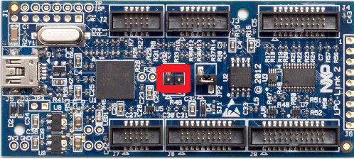
4.1.2 LPC-Link2 configuration
LPC-Link2 can operate as both a debug probe and an development board for the LPC4370
MCU. For exploring the LPC4370 with LPCScrypt:
• To boot from USB0: JP1 not fitted.
LPCScrypt User Guide - All information provided in this document is subject to legal disclaimers © 2014-2018 NXP Semiconductors. All rights reserved.
User Guide Rev. 2.1.0 — 23 January, 2019 9NXP Semiconductors LPCScrypt User Guide
• To boot from SPIFI: JP1 fitted.
Figure 4.2. LPC-Link2 JP1 Boot Pin
Note: The MCU on the LPC-Link2 has no internal flash.
4.2 Linux install notes
• Linux – Ubuntu 16.04 LTS and later
• Only (Intel/AMD) 64-bit versions of Linux are supported.
Note
LPCScrypt for Linux is a 64-bit application, so it will not run on 32-bit systems.
It is supported and tested only on the Linux distribution Ubuntu 16.04 LTS and
18.04 LTS.
The installer is supplied as an executable that installs the LPCScrypt components. The
installer requires root privileges, although, once it is installed, no special privileges are
required to use LPCScrypt. The installer will request a super-user password when it is
started.
4.2.1 Other Linux Distros
Due to the huge variation in capabilities of different Linux distributions and versions,
LPCScrypt may work on other distributions / versions but we cannot provide support if it
does not.
4.3 Installing host drivers
Depending on the chosen host, device drivers may be required as detailed below.
4.3.1 Windows: Installing DFU and VCOM drivers
During installation, the required drivers will be automatically installed. These drivers can
be managed if required by running lpc_driver_installer.exe located within the Drivers
subdirectory of the LPCScrypt installation.
4.3.2 Linux: Installing udev rules
During installation, the required drivers will be automatically installed.
4.3.3 Mac OS X
Mac OS X does not require any special procedure for working with the USB serial port.
LPCScrypt User Guide - All information provided in this document is subject to legal disclaimers © 2014-2018 NXP Semiconductors. All rights reserved.
User Guide Rev. 2.1.0 — 23 January, 2019 10NXP Semiconductors LPCScrypt User Guide
4.4 Booting LPCScrypt firmware
Before using the LPCScrypt host tool, the LPCScrypt firmware image must be downloaded
into the RAM of the target MCU. This is done by connecting the target’s configured boot
USB port to the host and using the boot_lpcscrypt script, located in the scripts directory
of the installation.
Note
Due to restrictions with the dfu-util utility used by boot_lpcscrypt, only one
unbooted MCU may be connected. However, they may be connected and
booted one at a time. After that, any number of MCUs with the LPCScrypt
firmware may be connected and programmed by the LPCScrypt host tool, each
of them communicating over a different USB serial (VCOM) port.
4.5 LPCScrypt serial ports
Once booted, the LPCScrypt firmware enumerates as a USB serial (VCOM) device on the
host. In most circumstances this will be detected automatically when LPCScrypt is launched
on the host.
If more than one MCU running LPCScrypt firmware is connected to a host, or other VCOM
connections exist, then you will be prompted to select the appropriate serial port, as below:
Multiple serial ports found:
COM5
COM7
Use -d serial_port to select
For more details regarding serial ports selection and potential problems, see Chapter 7.
LPCScrypt User Guide - All information provided in this document is subject to legal disclaimers © 2014-2018 NXP Semiconductors. All rights reserved.
User Guide Rev. 2.1.0 — 23 January, 2019 11NXP Semiconductors LPCScrypt User Guide
5. Simple Tutorial
5.1 Basic LPCScrypt usage
In this tutorial we are going to use LPCScrypt to program some applications into the internal
flash and SPIFI flash of a Keil MCB1857 or MCB4357 board. Ensure this board is configured
to boot from USB0 and has been reset (this may require ISP to be held during reset/power
on). See Section 4.4 on booting LPCScrypt firmware for more details.
5.1.1 Booting LPCScrypt
Open a command prompt on your host machine, navigate to the scripts subdirectory and
execute the command to download the LPCScrypt firmware to the target MCU.
For Windows this is:
boot_lpcscrypt.cmd
Alternatively, this script may be called directly from the LPCScrypt entry in the Windows
Start menu.
On non-Windows hosts, use:
./boot_lpcscrypt
A message similar to this should now be displayed, confirming that the LPCScrypt firmware
has been downloaded:
Booting LPCScrypt target with "LPCScrypt_48.bin.hdr"
LPCScrypt target booted
5.1.2 Obtaining information about the target MCU
Now we use LPCScrypt to tell us something about the target MCU. Navigate to the bin
subdirectory and enter a command such as the following.
lpcscrypt querypart
This displays details of the part and how much internal flash it has:
partID = 0xa001c830 0x0
decode = LPC4357: BankA 512 KB, BankB 512 KB
Core Clock = 180000000
We can also get more information about the flash — both internal flash and any connected
SPIFI flash devices:
lpcscrypt queryflash
In this example we have details of two banks of internal flash, one block of EEPROM and
external SPIFI flash:
LPCScrypt User Guide - All information provided in this document is subject to legal disclaimers © 2014-2018 NXP Semiconductors. All rights reserved.
User Guide Rev. 2.1.0 — 23 January, 2019 12NXP Semiconductors LPCScrypt User Guide
Number of Flash Devices = 4
Name = SPIFI
Base = 0x14000000
Size = 0x400000
Page = 0x100
Sector = 0x10000
Blank = 0xff
Buffer = 0x8000
-
Name = BankA
Base = 0x1a000000
Size = 0x80000
Page = 0x1000
Sector = 8-64KB
Blank = 0xff
Buffer = 0x8000
-
Name = BankB
Base = 0x1b000000
Size = 0x80000
Page = 0x1000
Sector = 8-64KB
Blank = 0xff
Buffer = 0x8000
-
Name = EEPROM
Base = 0x20040000
Size = 0x3f80
Page = 0x80
Sector = NA
Blank = 0x0
Buffer = 0x8000
We can also obtain more details on the SPIFI flash as below:
LPCScrypt queryspifi
Below you can see the device has been identified, the size and other configuration
parameters have been read from SFDP data.
Using SFDP derived data:
Device ID = JEDEC_ID_0x20_0xba_0x20
Device size = 0x4000000
Sector size = 0x10000
Page size = 0x100
Max clock = 80000000 Hz
SPIFI clock = 60000000 Hz
5.1.3 Programming internal flash
Having obtained some information on the target MCU, we will now program an image into
the internal flash:
lpcscrypt program ..\images\MCB1800_blinky_BankA.bin BankA
LPCScrypt User Guide - All information provided in this document is subject to legal disclaimers © 2014-2018 NXP Semiconductors. All rights reserved.
User Guide Rev. 2.1.0 — 23 January, 2019 13NXP Semiconductors LPCScrypt User Guide
Once programming is completed it will return a confirmation message, for example:
..
Programmed 5456 bytes to 0x1a000000 in 0.021s (258.923KB/sec)
Note
The flash address to program can either be specified as a numeric hex address
or (if programming from the base address of the flash) as the name returned
from a queryflash command. Images can be programmed at an offset from
the flash base address, but care must be taken to link and align such images
to a flash sector base address.
We can also run a verify operation to compare the image in flash with the programmed
binary:
lpcscrypt verify ..\images\MCB1800_blinky_BankA.bin BankA
Tip
LPCScrypt performs an automatic verify during programming so a separate
verify step is not necessary
which, once completed, will return a confirmation message like this:
.
Verified 5456 bytes to 0x1a000000 in 0.004s (1370.402KB/sec)
If you now reset the board, you should see the image you programmed running on the
target MCU.
Tip
Alternatively, you can run the image using the LPCScrypt command
gotoImage BankA.
5.1.4 Using a script
Rather than passing single commands to LPCScrypt, you can use the -s argument to pass
a file of commands. Thus we could combine the above sequence to program and verify
into a single script file called (for example) ‘bankAprog.txt’ and containing:
program ..\images\MCB1800_blinky_BankA.bin BankA
verify ..\images\MCB1800_blinky_BankA.bin BankA
We could then execute this script using:
lpcscrypt -s bankAprog.txt
5.1.5 Programming internal flash bank B
The commands for programming and running an image from bank B are similar to those
for bank A. However, an additional command is required to force booting from bank B,
because bank A is the default.
program ..\images\MCB1800_blinky_BankB.bin BankB
LPCScrypt User Guide - All information provided in this document is subject to legal disclaimers © 2014-2018 NXP Semiconductors. All rights reserved.
User Guide Rev. 2.1.0 — 23 January, 2019 14NXP Semiconductors LPCScrypt User Guide
verify ..\images\MCB1800_blinky_BankB.bin BankB
setboot BankB
The following command can then be used to switch back to booting the bank A image.
lpcscrypt setboot BankA
5.1.6 Programming SPIFI
Firstly, for a part with internal flash, you may need to erase the internal flash in order for
code in SPIFI to boot from reset. To do this use:
lpcscrypt erase BankA
lpcscrypt erase BankB
Then program the image into SPIFI flash using:
lpcscrypt program ..\images\MCB1800_blinky_SPIFI.bin SPIFI
Tip
LPCScrypt performs an automatic verify during programming so a separate
verify step is not necessary
Remember that you will need to change the boot jumpers in order to boot from SPIFIflash
at reset.
5.1.7 Erasing SPIFI
SPIFI flash can be erased in the same way as internal flash.
lpcscrypt erase SPIFI
Warning
Erasing some SPIFI devices can take many seconds so it may appear that the
process has hung. This is not the case – be patient!
You can also erase a portion of a flash device, as below:
lpcscrypt erasesector SPIFI
This will erase one sector of the SPIFI flash starting from the SPIFI flash base address.
Note: The size of one sector of a flash device is reported by the queryflash command.
Multiple sequential sectors can also be erased using a single command:
lpcscrypt erasesector SPIFI 4
Tip
Some SPIFI flash support optimised whole device erase, so for programming
large images, faster overall performance may be seen by performing an erase
before a programming operation.
LPCScrypt User Guide - All information provided in this document is subject to legal disclaimers © 2014-2018 NXP Semiconductors. All rights reserved.
User Guide Rev. 2.1.0 — 23 January, 2019 15NXP Semiconductors LPCScrypt User Guide
5.2 Image_manager utility and secure booting
Note
Support for encrypting images is not available in all versions of LPCScrypt.
Supplied as part of the LPCScrypt package is a utility called image_manager, which provides
two main functions. It can:
• add standard header information to a binary file required for either a DFU or a Secure
boot operation from SPIFI Flash (LPC18S/43S parts only)
• encrypt a binary file using a supplied AES key.
Full details on secure boot are given in the User Manual for the MCU. However, there are
some key points to note about secure booting from SPIFI flash.
• Any binary image designed for secure booting must be linked to run from RAM at
0x10000000 and be no larger than the size of the local SRAM block starting at
0x10000000. This is essential since the image will be decoded and copied into this SRAM
block before being executed.
Note
Check the User Manual for your MCU to determine the size of this SRAM block
The AES key used to encrypt the image must be programmed into the MCU OTP memory.
Important Warning
Programming an AESkey into the MCU is a one-time-only operation. The
programming of a key sets its value permanently in one-time-programmable
memory, and future debug connections are disabled.
Therefore under most circumstances this is the last operation to be performed before the
MCU enters service.
In operation, LPCScrypt is designed to be fully script driven. However, the examples in this
section explain some key points as separate operations.
5.2.1 Creating an image to run from RAM
Sometimes it can be useful to download an image (built to run at 0x10000000) into RAM
and execute it – for example, in order to test an image that you will later encrypt for secure
booting (which is covered in more detail in the next subsection).
To do this we first need to generate a version of the binary containing a header. Navigate
to the images subdirectory and enter:
..\bin\image_manager -i MCB1800_blinky_RAM.bin \
-o MCB1800_blinky_RAM.bin.hdr --bin
which will generate the required file with a header. The output should look like this:
image_manager v2.0.4 (Build 18) (Oct 7 2014 13:48:27)
Writing out file: MCB1800_blinky_RAM.bin.hdr, size - 4624 bytes
LPCScrypt User Guide - All information provided in this document is subject to legal disclaimers © 2014-2018 NXP Semiconductors. All rights reserved.
User Guide Rev. 2.1.0 — 23 January, 2019 16NXP Semiconductors LPCScrypt User Guide
Now, to download to RAM, you can use the boot_lpcscrypt script. First reset your board
with the boot pins set to boot from USB0, and then enter:
..\scripts\boot_lpcscrypt MCB1800_blinky_RAM.bin.hdr
This will download your executable image (instead of the default LPCScrypt firmware) to
RAM, and then execute it.
5.2.2 Programming an AES encrypted image to SPIFI flash for secure
boot
Develop and test an application using your favourite toolchain – such as LPCXpresso.
Ensure it is linked and tested to run from RAM at 0x10000000 and is less than the size of
the local SRAM bank at 0x10000000. Extract a binary image from the generated .axf file.
• DFU boot the LPCScrypt firmware onto the MCU.
• Call LPCScrypt with a single command to generate a 128-bit key from the MCU random
generator.
• Call Image Manager to encrypt the binary image with the 128-bit key and add the required
header.
• Call LPCScrypt and pass a single command to flash the encrypted image.
• Call LPCScrypt and pass a single command to verify the flash operation.
• Call LPCScrypt and pass a single command to program the AES 128-bit key into OTP
memory on the MCU.
Important Warning
Once an AES key is programmed into the MCU, no further debug operations
will be possible with that device.
boot_lpcscrypt
lpcscrypt genkeytarget
--->>> 977e4c70dd602705570b82f2c4333989
image_manager --key 977e4c70dd602705570b82f2c4333989 \
-i -o --bin
lpcscrypt program SPIFI
lpcscrypt verify SPIFI
If there are no errors and you no longer need to perform debug operations on this device,
do:
lpcscrypt aes_ProgramKey1 977e4c70dd602705570b82f2c4333989
5.2.3 Basic scripting
As described in Section 5.1.4, you can use the -s argument to pass a file of commands
to LPCScrypt in one operation. The following example script combines three of the steps
described above:
# commands to flash, verify and program an AES key
program SPIFI
LPCScrypt User Guide - All information provided in this document is subject to legal disclaimers © 2014-2018 NXP Semiconductors. All rights reserved.
User Guide Rev. 2.1.0 — 23 January, 2019 17NXP Semiconductors LPCScrypt User Guide
verify SPIFI
aes_ProgramKey1 977e4c70dd602705570b82f2c4333989
You would run it like this:
lpcscrypt -s
5.2.4 Advanced scripting
It is also possible to combine the scripting ability of LPCScrypt with the facilities provided
by the host system’s command line (shell scripts or batch files). The scripts subdirectory
of the LPCScrypt bundle contains example scripts.
For example, the ‘encrypt_and_program’ script creates a (random) AES key, encrypts a
binary image, programs it into SPIFI flash, and then sets the AESkey on the target MCU.
Its usage is:
encrypt_and_program
5.2.5 Testing secure boot images
Make sure the image works when DFU booted directly into RAM before you try to encrypt it.
When testing secure booting, you can encrypt a binary file with a ‘0’ key and test it on the
MCU without having programmed any AESkey into the MCU.
Warning
Do not program the MCU AESkey with 0. Doing this will have the same effect as
any other AESkey programming – no further debug operations will be possible
with this MCU. You can boot from a file that is encrypted with a ‘0’ key without
programming the AESkey.
LPCScrypt User Guide - All information provided in this document is subject to legal disclaimers © 2014-2018 NXP Semiconductors. All rights reserved.
User Guide Rev. 2.1.0 — 23 January, 2019 18NXP Semiconductors LPCScrypt User Guide
6. Reference
6.1 LPCScrypt
6.1.1 The LPCScrypt command-line tool
The command-line tool lpcscrypt reads commands, executes them on the target and
displays the results. The tool takes the following options.
Option Description
-h Display this help message.
-d devicename Use devicename for the USB serial port
connected to the target. Using ‘?’ as the
devicename will cause lpcscrypt to display
available usb serial ports and exit.
-s script Read a script from a file.
-t Read scripts from the terminal (stdin).
[ -x] command Execute ‘command’ only. Use of -x is
optional.
The -x, -s and -t options are mutually
exclusive.
-v name=value Define a variable name with the value value.
In script commands, surround variables with
square brackets (e.g. [myvariablename]) to
reference the variable in the script. Simple
text replacement is performed on each script
line.
-p Pause before each script command.
-e dnqst Set command echo options:
q (quiet) - echo nothing (default)
d (debug) - echo additional information
n (noisy) - echo everything
s (script) - echo script commands
t (target) - echo target commands
e (exit) - display a message on exit
Example invocations:
# Display help.
lpcscrypt -h
# Display information about the connected target
lpcscrypt -x targetinfo
# the '-x' is optional...
lpcscrypt targetinfo
LPCScrypt User Guide - All information provided in this document is subject to legal disclaimers © 2014-2018 NXP Semiconductors. All rights reserved.
User Guide Rev. 2.1.0 — 23 January, 2019 19NXP Semiconductors LPCScrypt User Guide
# explicitly select a serial device and read commands from the file 'script'.
lpcscrypt -d COM15 -s script
# Use /dev/ttyACM0 as the serial device and execute the command 'queryflash'.
lpcscrypt -d /dev/ttyACM0 queryflash
6.1.2 LPCScrypt commands
This table lists the commands that LPCScrypt supports. All of them are case insensitive.
The commands can be used in scripts (which are executed using lpcscrypt -s) or
individually with lpcscrypt -x.
Command Parameters Description
aes_programkey1 32_hex_digits takes an AES key of 32
hex digits and permanently
programs it as key1
aes_programkey2 32_hex_digits takes an AES key of 32
hex digits and permanently
programs it as key2
batchmode 0/1 sets ‘batch mode’ to reduce
command echo from the
target (issued automatically
by the command-line tool)
blankcheck flash_device (**) verifies that the flash device
has been set to its blank
value
call address starts executing code at
address
clockFast sets the target clock speed to
180MHz
clockSlow sets the target clock speed to
120MHz
datapacket offset data provides up to 32 words of
data to the data buffer (used
by the program and verify
commands)
databurst size offset checksum provides binary data to
the data buffer (used by
the program and verify
commands)
dataset num_words data clears the data buffer to the
byte value in data (used
by the program and verify
commands)
echo parameters echoes the parameters
(useful for displaying
messages to a user)
erase flash_device (**) erases the whole flash at the
base_address
LPCScrypt User Guide - All information provided in this document is subject to legal disclaimers © 2014-2018 NXP Semiconductors. All rights reserved.
User Guide Rev. 2.1.0 — 23 January, 2019 20NXP Semiconductors LPCScrypt User Guide
erasesector address erases the flash sector at the
address
flashSet address word programs a word of data
into a flash at address,
preserving all other values
genkeyhost uses the host to generate
a random 128-bit key
and display it (uses host-
specific UUID functions). Not
available in all versions of
LPCScrypt
genkeytarget uses the target to generate a
random 128-bit AES key and
display it. Not available in all
versions of LPCScrypt
gotoimage address fakes booting from the
provided address (loads
the SP from base_address,
loads the PC from
base_address+4 and starts
executing)
help displays the commands
available
memdisplay start_address (+) displays target memory
end_address (optional) step
otp_progBootSrc num calls ROM function to set
boot source – see MCU
documentation
otp_progJTAGDis calls ROM function to
disable JTAG permanently –
see MCU documentation
otp_progUSBID PID VID calls the ROM function to set
the USB PID and VID – see
MCU documention
otp_proggp0 (*) num num num num mask calls ROM function to
mask mask mask program OTP GP bank – see
MCU documention
otp_proggp1 (*) num num num num mask calls ROM function to
mask mask mask program OTP GP bank – see
MCU documention
otp_proggp2 (*) num num num num mask calls ROM function to
mask mask mask program OTP GP bank – see
MCU documention
otp_proggp2_0 num mask calls ROM function to
program OTP GP word – see
MCU documention
otp_proggp2_1 num mask calls ROM function to
program OTP GP word – see
MCU documention
LPCScrypt User Guide - All information provided in this document is subject to legal disclaimers © 2014-2018 NXP Semiconductors. All rights reserved.
User Guide Rev. 2.1.0 — 23 January, 2019 21NXP Semiconductors LPCScrypt User Guide
otp_proggp2_2 num mask calls ROM function to
program OTP GP word – see
MCU documention
otp_genrand calls ROM function to
generate random 128-bit
AES key
pause on/off/message pauses, waiting for user
input (setting pause mode
‘on’ asks the user to confirm
execution of each command)
print string prints the string
program [+c/+w1/+w2/+w4] programs (and verifies)
binary_file/fill_value the binary_file into the
flash_device (**) flash device starting at
flash_device. If +c is
specified, the vector
checksum is calculated
and inserted into the
image in memory before
programming. +w1, +w2 or
+w4 are used to program
memory with a 1-byte, 2-byte
or 4-byte fill_value with an
optional length of fill_length.
programpage address programs (and verifies) a
page from the data buffer
into the (flash) page starting
at address (used by the
program command)
resetCore calls out to the Reset
Generation Unit to perform a
core reset
queryEncode displays the unique code
identifier as used by CMSIS-
DAP
queryFlash displays information about
the connected internal and
external flash devices
queryID displays the 4-word unique
part identifier as: Word1
Word2 Word3 Word4
queryOTPMem displays OTP memory block
querypart displays information about
the target
querypartdetailed displays detailed information
about the target MCU
queryspifi displays information about
connected SPIFI devices,
from SFDP or recognised
device
LPCScrypt User Guide - All information provided in this document is subject to legal disclaimers © 2014-2018 NXP Semiconductors. All rights reserved.
User Guide Rev. 2.1.0 — 23 January, 2019 22NXP Semiconductors LPCScrypt User Guide
setboot BankA/BankB for parts with two internal
flash banks, sets the
appropriate bank to boot
setVidPid VID PID sets the USB VID and PID
into the OTP memory
SPIFISetSingle sets QSPI flash to single
speed – SFDP configured
flash only
SPIFISetDual this command will perform
no action
SPIFISetQuad sets QSPI flash to quad
speed (if supported) - SFDP
configured flash only
SPIFIRead sequential word read and
sum of whole device
SPIFIWrite programs whole device with
sequential words, requires
no host interaction
SPIFIReadReg command num replies send SPIFI byte command
and read number of
response bytes
SPIFIWriteReg command params send SPIFI byte command
with parameters
targetInfo displays information about
the target, including partID,
flash configuration and
unique ID
timer start/stop/print start starts a timer; stop
stops a timer; print displays
the current value of the timer
var name=value defines a variable called
name to have the value
value (most useful when
defined on invocation of
the lpcscrypt tool to pass
environment variables to the
script; reference a variable
in a script by surrounding
it with square brackets, e.g.
[myvariablename])
verify [+c/+i/+w1/+w2/+w4] verifies that the flash
binary_file/fill_value contents match the contents
flash_device ( fill_length) (**) of binary_file. If +c
is specified the vector
checksum is calculated and
inserted into the image in
memory before verifying. If
+i is specified, the vector
checksum is ignored during
the verify. +w1, +w2 or +w4
LPCScrypt User Guide - All information provided in this document is subject to legal disclaimers © 2014-2018 NXP Semiconductors. All rights reserved.
User Guide Rev. 2.1.0 — 23 January, 2019 23NXP Semiconductors LPCScrypt User Guide
are used to verify memory
against a 1-byte, 2-byte
or 4-byte fill_value with an
optional length of fill_length
verifypage address verifies memory at address
against the data buffer (used
by the verify command)
version displays version information
for the host application and
the target firmware
(*) not available in all ROM versions
(**) where flash_device can be: BankA, BankB, EEPROM, SPIFI, an address, or an
expression such as SPIFI+0x10000. The alias ‘all’ can also be used on the erase and
blankcheck commands to specify all memories.
# Use different ways to specify a target address.
lpcscrypt program SPIFI
lpcscrypt program SPIFI+0x10000
lpcscrypt program 0x14000000
lpcscrypt program 0x14010000
# Alias 'all' can be used on erase and blankcheck commands
lpcscrypt erase all
lpcscrypt blankcheck all
6.2 Image manager
The command-line tool image_manager adds a header to an executable binary file to create
a valid boot image for SPI boot or other use. It can also be used for encrypting a boot image
with an AES key. Note that boot headers are not needed for memory that can execute-in-
place, such as SPIFI or EMC.
6.2.1 Image manager command-line tool options
The image_manager tool takes the following options.
Option Description
-i input_binary_file_name name of the binary file to be processed
-o output_file_name name of the output binary file
--cde sets output file type to cde
--bin sets output file type to binary
--key aeskey uses this AES key, provided as 32 hex
digits, to encrypt the image. Not available in
all versions of LPCScrypt
--crc adds CRC to the image header
--size bytes image size in bytes (given in decimal)
--magic number Magic number for a header as two hex digits
(default is 1A); only valid for plain image
LPCScrypt User Guide - All information provided in this document is subject to legal disclaimers © 2014-2018 NXP Semiconductors. All rights reserved.
User Guide Rev. 2.1.0 — 23 January, 2019 24NXP Semiconductors LPCScrypt User Guide
--ibase base image base offset in bytes in decimal
--frame size image frame size in bytes in decimal (default
is 512); only valid for plain image
--help displays help text
Note: In all cases, options may be prefixed with single - or double -- dashes.
6.3 LPCScrypt example images
The images subdirectory of an LPCScrypt installation contains example binary files for the
Keil MCB18xx/43xx and LPC-Link2. These examples will flash the available LEDs to signify
what code is running and whether any errors have been detected by the self check code
within the binaries.
These binary files have a common name format:
[_board _][_examplename _][_MemoryDevice _].bin
An example is:
Link2_Small_SPIFI.bin
The LED flash patterns for the various example binaries are listed in the tables below.
+-----------+---------+----------------------+
| Board | Example | SPIFI |
+-----------+---------+----------------------+
| LPC-Link2 | Small | Blink 3 times, pause |
| LPC-Link2 | Medium | Blink 4 times, pause |
| LPC-Link2 | Fill | Blink 5 times, pause |
+-----------+---------+----------------------+
+----------+---------+----------+----------+----------+-----------+
| Board | Example | BankA | BankB | SPIFI | RAM |
+----------+---------+----------+----------+----------+-----------+
| MCB18/43 | Blinky | x......o | xx.....o | xxx....o | xxxx....o |
| MCB18/43 | Large | x.....oo | xx....oo | xxx...oo | xxxx...oo |
| MCB18/43 | Fill | x....ooo | xx...ooo | xxx..ooo | xxxx..ooo |
+----------+---------+----------+----------+----------+-----------+
x - flash
o - on
. - off
If an error is detected in the self-check code of the binary, the left and right LEDs will both
flash rapidly.
LPCScrypt User Guide - All information provided in this document is subject to legal disclaimers © 2014-2018 NXP Semiconductors. All rights reserved.
User Guide Rev. 2.1.0 — 23 January, 2019 25NXP Semiconductors LPCScrypt User Guide
7. Appendix A: LPCScrypt serial ports in depth
7.1 Multiple serial ports
When LPCScrypt firmware is booted, it will enumerate on the host as a USB serial (VCOM)
port. In normal operation LPCScrypt (host) will be able to detect and use the correct
serial port automatically. However this automatic detection cannot identify the port to use
if multiple USB serial ports are found. The solution is to manually identify the correct serial
port and specify it to LPCScrypt using the -d switch.
lpcscrypt -d ...
Identifying USB serial ports on the supported host operating systems is discussed below.
Note: If you try to run lpcscrypt and pass it the wrong serial port information, or run it
without booting the LPCScrypt firmware, then you will get an error similar to the following
(the details depend on the port and the host operating system):
Error com71: The system cannot find the file specified.
7.2 Host OS serial ports
7.2.1 Windows
The device will appear as a COM port (e.g. COM5). The COM port number will vary,
depending on the configuration of the PC, and whether other serial devices have been
installed. A number of methods are provided to list available serial ports.
• The LPCScrypt application can be run to display serial ports. Open a Windows Command
Prompt and run lpcscrypt -d ?, noting the COM port displayed.
• A script called ListLPCComPorts is provided in the scripts directory to list suitable ports.
To run this script, open a Windows Command Prompt, run the script, and note the COM
port displayed.
• The COM port number can also be found by looking in the Device Manager for “LPC
USB VCom Port” and noting the device name displayed.
7.2.2 Linux
With no other VCOM devices attached, the device will normally be /dev/ttyACM0.
• The LPCScrypt application can be run to display serial ports. Open a terminal and run
lpcscrypt -d ?, noting the device port displayed.
• Alternatively, open a terminal and type ls /dev/ttyACM* — the device will typically appear
with a name of the form /dev/ttyACM*, with the actual name depending on other serial
devices that are attached.
Common issues
After booting the LPCScrypt firmware, you may experience two issues when trying to use
the lpcscrypt command line tool
• /dev/ttyACM0: Permission denied. This error will be displayed if you have not installed
the udev drivers. To resolve this issue follow the instructions to Linux: Installing udev
rules, earlier in this document.
LPCScrypt User Guide - All information provided in this document is subject to legal disclaimers © 2014-2018 NXP Semiconductors. All rights reserved.
User Guide Rev. 2.1.0 — 23 January, 2019 26You can also read