Materials to Be Used in Future Magnetic Confinement Fusion Reactors: A Review
←
→
Page content transcription
If your browser does not render page correctly, please read the page content below
materials
Review
Materials to Be Used in Future Magnetic Confinement Fusion
Reactors: A Review
René Alba            , Roberto Iglesias *        and María Ángeles Cerdeira

                                          Department of Physics, University of Oviedo, E-33007 Oviedo, Spain
                                          * Correspondence: roberto@uniovi.es

                                          Abstract: This paper presents the roadmap of the main materials to be used for ITER and DEMO
                                          class reactors as well as an overview of the most relevant innovations that have been made in recent
                                          years. The main idea in the EUROfusion development program for the FW (first wall) is the use of
                                          low-activation materials. Thus far, several candidates have been proposed: RAFM and ODS steels,
                                          SiC/SiC ceramic composites and vanadium alloys. In turn, the most relevant diagnostic systems and
                                          PFMs (plasma-facing materials) will be described, all accompanied by the corresponding justification
                                          for the selection of the materials as well as their main characteristics. Finally, an outlook will be
                                          provided on future material development activities to be carried out during the next phase of the
                                          conceptual design for DEMO, which is highly dependent on the success of the IFMIF-DONES facility,
                                          whose design, operation and objectives are also described in this paper.

                                          Keywords: PFM; structural materials; RAFM; ODS; SiC; vanadium alloys; diagnostics; ITER; DEMO;
                                          IFMIF-DONES

                                          1. Introduction
Citation: Alba, R.; Iglesias, R.;
                                                The global energy outlook is currently going through a time of crisis and uncertainty
Cerdeira, M.Á. Materials to Be Used
in Future Magnetic Confinement
                                          as a result of the excessive use of and dependence on fossil fuels over the last century. This
Fusion Reactors: A Review. Materials
                                          is why a transition to new energy sources must be urgently addressed, with the need to
2022, 15, 6591. https://doi.org/          improve efficiency and opt for a decarbonized mix in which nuclear energy seems likely
10.3390/ma15196591                        to play a key role. When talking about nuclear energy, one tends to think of the present
                                          day technology (fission), but the reality is that a new means of energy production that will
Academic Editors: Linjiang Chai
                                          completely change the current paradigm is getting closer every day. Nuclear fusion energy
and Ning Guo
                                          offers the prospect of a safe, inexhaustible and waste-free energy source for generations to
Received: 27 July 2022                    come. Despite this, it also presents certain science and engineering challenges that, so far,
Accepted: 16 September 2022               have been insurmountable due to the extreme conditions and plasma instabilities faced
Published: 22 September 2022              by the materials of these future reactors. The premise of this review is to try to analyze
                                          the horizon of new possibilities that the development of nuclear fusion is allowing and to
Publisher’s Note: MDPI stays neutral
with regard to jurisdictional claims in
                                          contribute, as far as possible, to clarify what are and what could become the materials that
published maps and institutional affil-
                                          will facilitate the success of ITER and in the future of DEMO.
iations.
                                          2. Nuclear Fusion
                                                Nuclear fusion is a reaction involving light atomic nuclei and nucleons, so that when
                                          two of these nuclei join to form a heavier one, energy is given off. It is the basis for the
Copyright:    c 2022 by the authors.      existence of stars like the Sun. This process initially requires the joining of a proton with
Licensee MDPI, Basel, Switzerland.        another proton, an event known as the proton-proton chain, which was discovered in 1939
This article is an open access article    by the German physicist Hans Bethe [1].
distributed under the terms and                 Naturally, replicating this process on Earth requires in-depth research and develop-
conditions of the Creative Commons        ment. Incidentally, there is one element of particular interest for fusion due to its simplicity
Attribution (CC BY) license (https://     and abundance, hydrogen, which is precisely the one used by the Sun. Specifically, two of
creativecommons.org/licenses/by/
                                          its isotopes, deuterium (D) and tritium (T), are of interest.
4.0/).

Materials 2022, 15, 6591. https://doi.org/10.3390/ma15196591                                               https://www.mdpi.com/journal/materials
Materials 2022, 15, 6591                                                                                               2 of 39

                                This process is characterized as an exothermic reaction, where the nucleons must be
                           very close (∼1 fm) for the strong nuclear interaction to unite them and thus overcome
                           the electromagnetic repulsion, called the Coulomb barrier. It is also necessary to reach
                           temperatures of millions of degrees for this reaction to take place. Almost as soon as
                           physicists learned that solar energy could only be the product of nuclear fusion, they
                           discovered, however, that the temperature at the center of our star (about 15 million
                           degrees) is insufficient for hydrogen nuclei to actually come together at the necessary
                           distance. So how is it possible for nuclear fusion to occur in the Sun? To explain this, we
                           must resort to quantum mechanics and one of its most renowned concepts, the tunnel
                           effect, that allows certain particles to overcome the Coulombian energy barrier without
                           actually reaching its maximum value. Despite this, it is still necessary to reach enormous
                           temperatures indeed. This is why fusion is described as a thermonuclear process.
                                As mentioned above, the most viable reaction for the first generations of nuclear fusion
                           reactors is the one between deuterium (2 H) and tritium (3 H) (Figure 1), obtaining 17.6 MeV
                           of energy that translates into an alpha particle or He nucleus and a fast neutron.
                                                 2
                                                     H +3 H →      4
                                                                       He (3.52 MeV) + n (14.06 MeV).                     (1)

                           Figure 1. Nuclear fusion reaction. Reprinted from Wykis/WikimediaCommons.

                                Why use these H isotopes and not others? This is because the cross section (which
                           defines the probability of success of a nuclear reaction between a target and an incident
                           particle. Its SI unit is the barn, 1 barn = 10−28 m2 ) of this process is very high for relatively
                           low temperatures.
                                Another fundamental reason is the availability of these isotopes. D can be easily found
                           in seawater (an estimated 30 g/m3 ). T, on the other hand, is a radioactive and unstable
                           element (decay constant T1/2 = 12.3 years) which is produced naturally in small quantities
                           when cosmic rays (98% protons) strike the H atoms present in the atmosphere. It can also
                           be obtained as a product in CANDU NPP [2].
                                There are approximately 40 kilograms of T on the planet, so it is vital to find an
                           alternative method to reproduce it on a large scale.
                                                        6
                                                            Li + n =4 He +3 H + 4.86 MeV
                                                        7
                                                                                                                          (2)
                                                            Li + n =4 He +3 H + n − 2.5 MeV .

                                 T breeding consists of irradiating a Li blanket with the neutrons produced in the fusion
                           reaction itself (see Equation (2)). This generates the T that will supply the reactor. Definitely,
                           this is one of the greatest technological challenges that ITER and its related projects will
                           have to face.
                                 On the other hand, natural lithium (92.5% 7 Li y 7.5% 6 Li) is an abundant element in
                           the earth’s crust (30 ppm) and is found in lower concentrations in the sea. The thickness
                           of the blanket is large enough (∼m) to slow down the neutrons produced by the fusion
                           reactions. Upon impacting with the walls, their energy is transferred in the form of heat.
                           This heats water that turns into steam, which is then used to turn a turbine and hence
Materials 2022, 15, 6591 3 of 39
generate electricity. To get an idea of the efficiency of this process, the use of 1 kg of D-T
has the energy equivalence of 8000 tons of oil.
The breeding blanket (BB) is one of the most complex and important components of
future fusion reactors, as it is not only responsible for the extraction of energy but also for T
breeding in order to have a self-sufficient facility (tritium breeding ratio, TBR > 1) [2,3].
This parameter is defined as the average number of T atoms bred per T atom burned. It
should be higher than 1.15 in order to take into account T losses which cannot be avoided
in a real fusion reactor [4].
Tritium transport modelling allows experts to predict how this element will move
towards the systems that have to recover it in order to refuel the plasma. In doing so, two
fundamental considerations must be taken into account. Firstly, tritium does not simply
go from point A to B, as it is a gas that diffuses easily. This can happen especially at high
temperatures, as it can enter and mix with materials in pipes, valves and other components
along the way. Secondly, tritium is radioactive, so it is of great interest in terms of nuclear
safety and radiological protection to know where it can accumulate.
There are two options for the commercial development of nuclear fusion, magnetic
or inertial confinement. This review will look at the former, as it has become the more
advanced option with a higher probability of success.
3. ITER: The Project That Might Change the Future
3.1. What Is ITER?
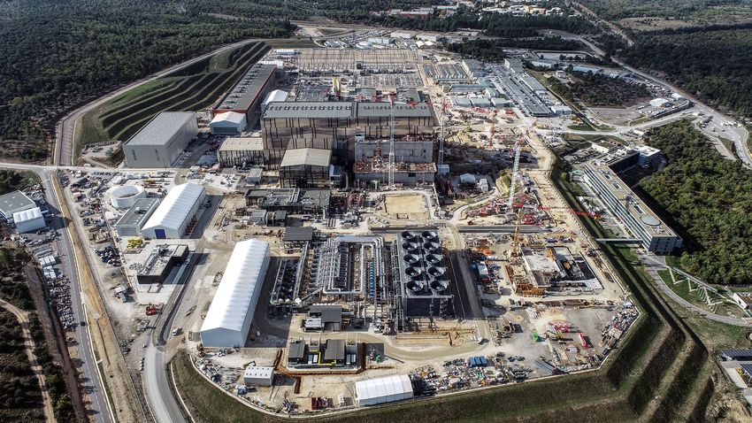
ITER is the most ambitious energy project in the world today and is located in the
town of Cadarache in southern France (Figure 2). Up to 35 nations (the 27 countries of the
EU together with Switzerland, the United Kingdom, China, India, Japan, Korea, Russia
and the United States) are collaborating to build the world’s largest Tokamak (Axisymmetric
toroidal chamber characterized by a large toroidal magnetic field, moderate plasma pressure
and relatively small toroidal current), a magnetic confinement fusion device designed to
demonstrate the viability of fusion as a large-scale, carbon-free energy source.
In turn, the technologies, materials and physical regimes required for large-scale
commercial electricity production will be tested.
Figure 2. Aerial view of the ITER site. Reprinted from Ref. [5]. Credit c ITER Organization, 2022.
Thousands of engineers and scientists have contributed to the design of ITER since the
idea of a joint international fusion experiment was first launched in 1985. The participating
members have committed themselves over a period of about 40 years to build and operate
the experimental device until fusion reaches a point at which DEMO can be launched.
3.2. What Are the Main Objectives?
The amount of fusion energy a tokamak is capable of producing is a direct result of
the number of fusion reactions taking place inside it. The larger the vessel, the greater the
plasma volume and thus the greater the potential fusion energy. This has its trade-offs in
Materials 2022, 15, 6591                                                                                            4 of 39

                           terms of cost, which is usually the case in projects based on economies of scale, typical of
                           traditional nuclear energy production. ITER has been specifically designed to:
                           1.     Produce 500 MW of fusion energy.
                           2.     Demonstrate the safety features of a fusion device.
                           3.     Test the reproduction of T with TBM (Test Blanket Modules).
                           4.     Demonstrate the integrated operation of technologies for a fusion plant.
                           5.     Achieve a D-T plasma in which the reaction is maintained by internal heating [6,7].

                           3.3. When Will the First Plasma Be Obtained?
                                 The first ITER plasma is scheduled for December 2025. As of 31 July 2022, 77.1% of the
                           work required for the first plasma has been completed [5].
                                 Beyond its symbolic importance, the first plasma will also be a litmus test for the
                           project, as it will be the first occasion to verify the correct alignment of the machine’s
                           magnetic fields as well as the correct functioning of key systems (vacuum vessel, magnets,
                           and critical plant systems).
                                 The first plasmas will use H, He or a mixture of both. This is why the initial processes
                           do not require a D-T fuel. Since many of the heating systems are optimized for D-T type
                           plasmas in order to achieve H-mode (a high plasma confinement operating regime which is
                           reached when a certain heating threshold is exceeded [8]), they will operate at a reduced
                           intensity that will gradually increase over the years. The first low-power H-plasma, which
                           will last a few milliseconds, will be followed by other “shots” of higher power and longer
                           duration. Finally, the first production of D-T fusion energy will take place during the
                           nuclear phase of the machine, expected around 2035 [9].

                           3.4. Materials Design Requirements
                                For the range of expected operating conditions (including possible accident scenarios)
                           in ITER and with even greater relevance to DEMO, a qualified database must be gen-
                           erated to demonstrate that candidate materials meet a number of indispensable design
                           requirements. Some of these are:
                           •      Good strength, ductility and toughness.
                           •      Radiation resistance and nonactivation properties after irradiation.
                           •      Resistance to creep rupture, fatigue cracking and creep-fatigue interactions.
                           •      Good resistance of mechanical and physical properties against He embrittlement.
                           •      Acceptable chemical compatibility and corrosion resistance with fusion-specific breeder
                                  materials (e.g., Be, LiPb) [10].

                           4. Plasma Facing Materials
                                One of the most sensitive processes taking place in a nuclear fusion reactor is the
                           interaction with the hot plasma, which is at temperatures higher than the core of the sun.
                           PFMs and PFCs are those materials/components that cover almost the entire internal
                           surface of the VV and represent the interface between the plasma and the rest of the
                           tokamak. They are part of two systems: the blanket (which includes the FW) and the
                           divertor, which occupy areas of 610 and 140 m2 , respectively [11].
                                The lifetime of a PFM is limited from ∼100 dpa (a dpa, displacements per atom, is
                           the number of times that an atom is displaced a given fluence. It is a unit for quantifying
                           irradiation damage that is strongly dependent on the material in question). The plasma-
                           walls interaction processes are associated with thermal loads of up to 20 MW/m2 in
                           continuous thermal periods and can reach the GW/m2 range when an ELM occurs. ITER
                           will not only seek to demonstrate the feasibility of the D-T process but will also be the first
                           test device for PFMs and PFCs in extreme radiation scenarios. Some of the most serious
                           damaging mechanisms to be considered in these materials are:
                           (i)    T retention.
                           (ii)   H-bubble induced fragility.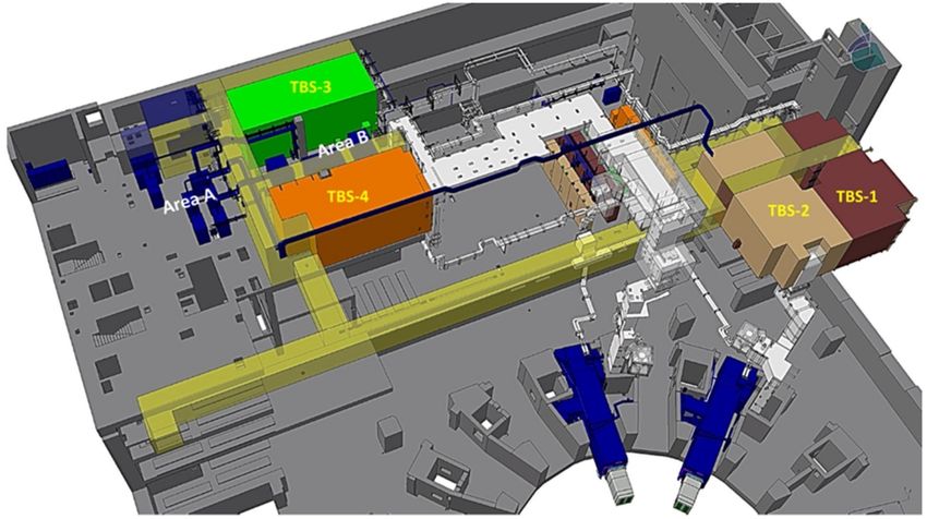
Materials 2022, 15, 6591                                                                                                 5 of 39

                           (iii)   High velocity impacts of dust particles in the PFM.
                           (iv)    Possible degradation, transmutation and activation.
                           (v)     Thermally induced defects due to cracking and melting of PFM.
                           (vi)    Thermal fatigue damage produced in the joints between the PFM and the heat
                                   sink [12,13].
                                Eighty percent of the enormous amounts of heat and energy that will be produced in
                           the fusion process will escape in the form of fast neutrons (14.1 MeV). Since these particles
                           have no charge, they cannot be redirected by means of a magnetic field to a specific location.
                           This has been one of the greatest engineering challenges from the outset, as the entire
                           FW will be exposed to an intense bombardment of highly energetic neutrons; therefore,
                           the components that will face the plasma must meet several indispensable design criteria:
                           •       Be strong enough to withstand such high radiation and temperature. The material
                                   chosen should have good thermal conductivity to easily evacuate heat, but at the
                                   same time cannot be readily activated, as the components are expected to last at least
                                   20 years before being replaced.
                           •       Be capable of effectively dissipating such heat, which, recovered through a cold water
                                   circuit, will be the heat that will generate electrical power in a realistic NPP. For a
                                   material to be considered as a potential PFM component, good compatibility with
                                   the hot fusion plasma, i.e., a low atomic number, Z, is a must, as well as an excellent
                                   sputter (a physical process in which atoms in a solid-state (target) are released and pass
                                   into the gas phase by bombardment with energetic ions) resistance.
                           •       Alternatively, tokamaks with high-Z materials such as tungsten (W) must be operated
                                   in such a way as to guarantee that the net impurity influx into the plasma should be
                                   so low that the critical impurity concentration is not exceeded. This is due to the fact
                                   that since this material has a high Z, it cannot be completely ionized, causing some of
                                   its electrons to remain free and radiate energy, thus cooling the plasma [12,14,15].
                                A brief analysis of the loads that the PFCs will undergo in the upcoming fusion
                           experimental projects is presented in Table 1. It can be seen that the step between ITER
                           and DEMO is much larger than between DEMO and PROTO (DEMO’s successor, expected
                           to become the first commercial nuclear fusion reactor after 2050), hence the need for an
                           intermediate materials testing facility between ITER and DEMO.

                           Table 1. Loads suffered by the PFCs in the FW. Adapted from Ref. [16].

                                                          ITER             DEMO              PROTO               Units
                                   Heat flux                0.3              0.5               0.5           MW/m2
                                 Fusion power              0.5               2.5                5              GW
                                Neutron damage
Materials 2022, 15, 6591                                                                                            6 of 39

                                The main aims of DEMO are to:
                           •   Achieve T self-sufficiency.
                           •   Solve all physical and technical issues related to the plant and demonstrate reactor-
                               related technology.
                           •   Achieve adequate availability/reliability operation over a reasonable time span (while
                               ITER is expected to work with 400 s pulses and a long dwell time, DEMO will work
                               with long pulses (>2 h) or even at a steady state) [17,18].
                                Materials for the DEMO reactor must be chosen considering the high doses of irra-
                           diation produced by neutrons with a thermonuclear reaction energy spectrum and the
                           very high heat load on the inner wall of the chamber. This can lead to significant in-vessel
                           material damage. It will be necessary to develop and test new materials for construct-
                           ing the DEMO thermonuclear reactor and solve issues related to their commercial-scale
                           manufacture [15,17].
                                The blanket supposed to be used in ITER is in fact unsuitable for the future DEMO
                           thermonuclear reactor. The envisaged materials can only withstand a small neutron flux
                           and the exit coolant temperature is too low to ensure efficient power generation. The next
                           step after ITER is to elaborate the design of DEMO and a thermonuclear power plant. Their
                           linear dimensions will be about 50% larger than those of ITER, and their fusion power will
                           be 5 and 7 times higher, respectively [15].
                                It appears that pilot plants and reactors may experience rates of net erosion and
                           deposition of PFC material in the range of 103 –104 kg/year, values well above those
                           expected in ITER. The deposition of such massive quantities of material has the potential to
                           interfere with pilot plant and reactor operation and to seriously compromise the safety of
                           the DT cycle. For example, elevated dust levels due to exfoliated and detached deposits
                           can lead to a high risk of dust explosion. Other adverse effects due to the accumulation of
                           unwanted eroded material at critical locations could result in the appearance of cracks in
                           the cooling channels due to thermal stress [19].
                                The DEMO design and R&D activities will benefit largely from the strongest ex-
                           perimental supporting evidence that will be gained from the design, construction and
                           operation of ITER. Due to the differences (in terms of size and, especially, in terms of ITER’s
                           wider mission) between the two devices, not all ITER solutions are directly applicable to
                           DEMO [18,20].

                           4.1. Tungsten
                                 Nowadays, tungsten is considered the most efficient material for components fac-
                           ing high heat flux, mainly due to its high melting point (T = 3422 ◦ C), good thermal
                           conductivity (160 W/m·K), excellent high temperature stability and low T retention [12,21].
                                 However, major concerns regarding the use of W in fusion reactor applications include
                           its inherent brittleness at low temperature and the embrittlement due to recrystallization
                           and neutron irradiation. To overcome these drawbacks, several efforts have been made to
                           modify W through grain refining, alloying, dispersion of secondary phases, and formation
                           of composites.
                                 Although W and CFCs were initially considered as the most promising PFMs, the fact
                           is that at the end of 2013, the decision was made to discard CFCs due to their tendency to
                           retain T and to opt for a fully tungsten-armoured divertor [22].
                                 A single null divertor (characterised by toroidal symmetry and one X-point or “null”) is
                           to be installed in the bottom area of the VV of the ITER tokamak. It will extract the heat
                           and ash produced in the fusion reaction, minimize plasma contamination and protect the
                           surrounding walls from thermal and neutron fluxes.
                                 Specifically, the divertor will consist of 54 divertor cassette assemblies (CAs) operated
                           by remote handling (Figure 3). Each of these CAs includes a cassette body (CB) and three
                           PFCs, namely the internal and external vertical targets (IVT and OVT) and the dome.
                           In addition, each of these modules will house diagnostic components for plasma control,
                           evaluation and optimization [11,12].
Materials 2022, 15, 6591                                                                                                      7 of 39

                           Figure 3. Parts of one of the 54 divertor modules. Reprinted with permission from Ref. [11]. Credit c ITER
                           Organization, 2019.

                                The IVTs and OVTs are placed at the intersection of the magnetic field lines where the
                           particle bombardment will be particularly intense in ITER. The heat flux to which these
                           components are subjected is estimated to be between 10 and 20 MW/m2 . Materials and
                           cooling methods that cannot be used in the FW may be used in the divertor, mainly due to
                           the presence of coils located at the bottom of the chamber that bend the outermost field
                           lines to enter the divertor [14].

                           4.1.1. ITER Design
                                 During the last decades, several PFC designs have been developed with W. The most
                           efficient are the monoblock and flat-tile types.
                                 These models (Figure 4) consist of modules that have been machined from a PFM
                           and attached to a water-cooled heat sink made of a metalic alloy. The joints between the
                           PFM and the heat sink must acquire very high mechanical strength to tolerate the high
                           temperatures and keep the modules uniformly in position. Each of these is equipped with
                           a cylindrical hole necessary for the junction between the PFM and the heat sink—usually
                           made of CuCrZr.

                                                          (a)                                (b)
                           Figure 4. Main PFC designs for ITER. The charged particles depositing their energy are guided by
                           the magnetic field lines. (a) Monoblock design. (b) Flat tile design. Reprinted from Ref. [12].

                                Despite its good performance, the flat tile design (Figure 4b) presents the possibility of
                           local overheating of the shielding plate due to the incidence of plasma particles. The loss of
                           even a single tile is considered a rather serious event, as it would lead to the degradation of
                           joints in the adjacent tiles (so-called cascade failure) [12,23].
                                Therefore, it has been decided that the ITER divertor will be completely made of
                           monoblock W due to its greater robustness versus possible accident conditions. Thus, both
                           IVTs and OVTs will be completely covered with this water-cooled material (Figure 5a) [24].

                                                         (a)                       (b)
                           Figure 5. Prototypes of W designs as PFC for ITER. (a) Monoblock design. (b) Flat tile design.
                           Reprinted from Ref. [12].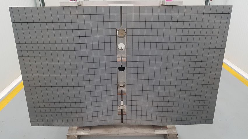
Materials 2022, 15, 6591                                                                                              8 of 39

                           4.1.2. Radiation Effects
                               The much-feared effect that radiation can have on the divertor components in ITER is
                           shown in Figure 6.

                           Figure 6. Surface damage with cracks induced by electron beam pulses. Reprinted from Ref. [12].

                               In this case, quite serious macroscopic damage resulting from cyclic thermal loads
                           simulating ELMs can be observed. Specifically, 105 pulses with a heat flux of 12 MW/m2
                           have been applied to a W sample preheated to 700 ◦ C. It shows a very intense degradation
                           due to the formation of a dense network of cracks on the surface. The 105 pulses of this
                           experiment correspond to an operating time of only 10 standard plasma discharges in
                           ITER. It points out the potential danger that these pulses can represent to this type of
                           materials [12].

                           4.1.3. Smart Alloys
                                 Due to its excellent properties, W has also been chosen as a prime PFM candidate for
                           DEMO. However, certain accidental models have revealed several drawbacks related to
                           the use of pure W. Those are its intrinsic low temperature brittleness, neutron-induced em-
                           brittlement and recrystallization resistance [21]. To prevent this, new modalities have been
                           developed and tested under fusion-relevant conditions. These include the modification of
                           its granular structure and the combination with several alloying elements and compounds
                           (Mo, Ti, Y2 O3 , ...) to increase strength and recrystallization resistance. The latter are the
                           so-called smart alloys (which automatically adapt their properties to the environment [25])
                           (SA) [12,23].
                                 One of the major concerns of using pure W in DEMO is related to its behavior under
                           a LOCA with air ingress in the VV. Under those circumstances, the temperature of the
                           tungsten cladding could reach 1000 ◦ C and remain at such a high level for several weeks.
                           Tungsten oxidizes and radioactive, neutron-activated tungsten oxide sublimates into the
                           environment at such a high temperature.
                                 During an accident, the remaining alloying elements in the bulk will diffuse to the
                           surface and form their own oxides, protecting tungsten from oxidation and subsequent
                           sublimation into the atmosphere. Recent studies have demonstrated the benefits of systems
                           based on W-Cr-Y, which are produced by mechanical alloying (a ball milling process where
                           a powder mixture placed in the ball mill is subjected to a high-energy collision from the
                           balls. The process is usually carried out in an inert atmosphere [26] ) (MA) and compacted
                           by FAST. These SA have demonstrated very high oxidation resistance and contain Cr as
                           an oxidizing alloying element and Y as an active element stabilizing and regulating the
                           chromium transport in the alloy system [27,28].
                                 Despite all their development, there are still open questions in both the understanding
                           of the physics and the technological development of SA systems. The role of Y in the
                           stabilization of a W-Cr solid solution still needs to be further understood as well as the
                           technology of joining SAs with the corresponding structural materials. At the same time,
                           the scale of fabrication at the industrial level needs to be improved. Finally, it is of vital
                           importance to carry out a thorough evaluation of the effect of neutrons and impurities as
                           well as transmutation on alloy performance [28].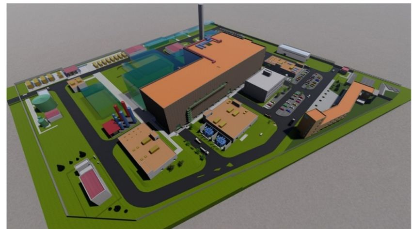
Materials 2022, 15, 6591                                                                                             9 of 39

                           4.1.4. Tungsten Fiber Reinforced Tungsten (W f /W)
                                The intrinsic brittleness of W is of great concern during possible transients with high
                           heat loads. To reduce this brittleness, numerous procedures have been investigated to
                           increase the toughness of the material. However, traditional intrinsic toughening methods
                           present limitations for applications in melting environments, where high-temperature
                           recrystallization phenomena can occur, causing severe internal damage.
                                To increase fracture toughness (the resistance of brittle materials to the propagation of
                           flaws under an applied stress) and thus improve the intrinsic brittleness of W, tungsten
                           fiber-reinforced tungsten composites (W f /W) are being developed for use in the divertor
                           of future fusion reactors.
                                Thus far, two main fabrication approaches have been established: powder metallurgy
                           (PM) and chemical vapor deposition (CVD) processes (Figure 7). For both cases, improved
                           mechanical properties have been demonstrated. Generally, W f /W composites created by
                           CVD contain 150 µm diameter unidirectional tungsten fibers coated by an interface and
                           embedded in a W matrix [23,29–31].

                                                             WF6 + 3H2 −→ W + 6HF                                       (3)

                                                              (a)                      (b)
                           Figure 7. (a) PM W f /W prototype (b) typical fracture surface of CVD W f /W. Reprinted with
                           permission from Ref. [29]. Credit c IOP Publishing, 2021.

                                The CVD process (see Equation (3)) consists of applying an interface layer (e.g., Y2 O3 )
                           to the fibers, exposing the composite to WF6 and H2 at temperatures between 573 and
                           1073 K. The fibers and CVD matrix have a major influence on the microstructure, potentially
                           leading W f /W composites to present different properties to those of pure W material
                           when eventually exposed to a fusion environment. Despite the fact that certain fabrication
                           aspects still need to be further investigated, CVD is potentially one of the most cost-effective
                           processes due to its fast deposition rate and high mass production from a reduced amount
                           of material [31,32].
                                Currently, the role of K-doping in W fibers is being studied, since it has been shown
                           to delay heat exposure-induced embrittlement at least up to 1600 ◦ C, although a strong
                           reduction in fiber strength has also been observed in tests conducted at elevated tempera-
                           tures [33].
                                This doped W contains nanobubbles (∼nm) that include K atoms (∼ppm) dispersed
                           mainly at grain boundaries (a 2D defect in a crystalline structure that tends to reduce the
                           electrical and thermal conductivity of the material) (GB). Because K bubbles hinder the
                           movement of these boundaries and dislocations, they are able to improve thermal shock re-
                           sistance and mechanical properties at high temperature as well as prevent recrystallization.
                           In addition, it is expected that the embrittlement induced by neutron irradiation can be sup-
                           pressed since it contains numerous GB, which act as sinks for the defects produced. On the
                           other hand, the addition of rhenium (Re) is also considered as another very promising
                           procedure, namely as a solid solution alloy reinforcement [34,35].
                                These materials have been shown to overcome the low temperature brittleness of W.
                           However, their main problem is industrial scale-up, which requires more effort over time
                           and has led to the decision not to consider this material for the DEMO start-up application
                           but to treat it as a high-potential material for further applications (e.g., PROTO) [23].
Materials 2022, 15, 6591                                                                                           10 of 39

                           4.2. Beryllium
                                Beryllium (Be) has been on the candidate list as a PFM since the late 1980s. With the
                           decision to use Be as the material for the ITER FW, research on its conditions and aspects
                           most relevant to fusion has accelerated [36,37].
                                During ITER operation, the FW coating will be subjected to cyclic thermal loads,
                           resulting in fatigue loads that can trigger melting, cracking, evaporation, and surface
                           erosion [38].
                                Be has been selected due to its low atomic number (Z = 4), which minimizes radi-
                           ation losses of the sputtered atoms in the plasma (that depend on Z2 ), its good thermal
                           conductivity and its oxygen uptake capacity that contributes to maintaining a high level of
                           plasma purity [11,12]. Beyond ITER, the three Be grades that are considered candidates for
                           the FW of a future fusion reactor are:
                           •    CN-G01 (China).
                           •    S-65 VHP (USA).
                           •    TGP-56PS (Russia).
                               These differ mainly by chemical composition, PM process used or compression
                           method [38].

                           4.2.1. Prototype for Use in ITER
                                 A total of 440 panels (FWP) will provide a protective barrier for all systems beyond the
                           VV. To get an idea of the technological challenge and the magnitude entailed by the ITER
                           project, it is sufficient to analyze the temperature gradient existing between the hot plasma
                           (150 × 106 ◦ C) and the superconducting coils (−269 ◦ C) that will confine it, separated by a
                           mere six meters.
                                 In essence, the panels are made of a 6–10 mm layer of beryllium bonded to a copper
                           alloy heat sink mounted on a 316L stainless steel (austenitic steel composed of Cr-Ni-Mo and
                           with a low C content) structure (Figure 8). Europe will be responsible for the production of
                           the first 215 FWPs, while China and Russia will provide the rest of them [39,40].

                           Figure 8. Prototype panel for the FW manufactured by Framatome. Reprinted from Ref. [39].

                                In turn, Be is one of the reference neutron multipliers for the various TBM designs and
                           is used in the form of pebble-beds. The process at the most advanced stage of development
                           is the rotating electrode process (REP), which allows the fabrication of pebble-beds of
                           typically 1 mm [11].

                           4.2.2. Beryllides
                                 Despite being considered one of the most promising materials, the main drawbacks of
                           beryllium’s application as PFM are its relatively low melting point (T f = 1278 ◦ C) as well
                           as its high toxicity [11,12].
                                 Beryllium intermetallic compounds (also called beryllides) such as Be12 Ti, Be12 V y
                           Be12 Zr are the most promising advanced neutron multipliers for DEMO, specifically for
                           HCPB design [41,42].
                                 The main consequence of neutron irradiation is significant He and T production, re-
                           sulting in swelling and loss of strength-related properties of beryllium composites. DEMO-
                           oriented R&D has focused on beryllides, as they promise to offer improved long-term
                           material performance, as well as resulting in a much lower H production rate compared to
                           pure Be [11].
Materials 2022, 15, 6591 11 of 39
Preliminary studies on the thermal desorption of He and T from titanium beryllium
(Be12 Ti) have shown that this material has a much lower retention tendency, in addition to
having a higher melting point. Some of its strengths are:
• Swelling as a result of exposure to neutron irradiation occurs to a lesser extent.
• It has a higher melting point (1593 ◦ C), lower activation and higher corrosion resistance.
• It has a sufficiently high beryllium content (69.3 wt. %) for efficient neutron multiplica-
tion/moderation [41–43].
All these advantages have opened the door to more extensive studies of the nuclear,
physical and mechanical properties of this material with the possibility of further use in
nuclear technology and high-temperature instrumentation.
4.3. Diamond
Due to its high Z, the presence of W in the interaction with the plasma significantly
affects its stability. On the other hand, diamond has a low Z, has excellent thermal properties
and thanks to its sp3 structure has a low T retention rate. For all these reasons and due to
its outstanding thermal conductivity, diamond can be doped into the tungsten matrix to
reduce the damage on the material.
One of the approaches that have been proposed has been to form a W/diamond
composite material via SPS, which would allow the thermal conductivity of pure W to be
improved. Another approach is to form diamond films via MWCVD, which, due to its
chemical purity and perfect adhesive property, would allow to improve the PFM properties
under high thermal loading conditions.
Both the interfacial bonding and thermal conductivity of the composite with a W-
coated layer are strengthened compared to uncoated composites. The volume fraction of
diamond particles in the composites is around 10–50%, and an 18% increase in thermal
conductivity is achieved over pure W [44,45].
Figure 9 shows the microstructure of the fracture surfaces of diamond particle-based
composites. As can be seen, for the uncoated composites, more obvious cracks appear
between the diamond particles and the tungsten matrix. For the coated composites, the size
and number of cracks are significantly reduced [45].
Figure 9. Microstructure of fractured surfaces: (a) uncoated and (b) coated. Reprinted with permis-
sion from Ref. [45]. Credit c Elsevier, 2019.
Consequently, the addition of diamond to W facilitates the manufacture of materials
with outstanding strength and toughness at temperatures above 1200 ◦ C. These compos-
ites are considered valid candidates for the FW of future fusion reactors, as they would
combine excellent thermal creep corrosion toughness and resistance to neutron radiation
damage [46].
It may seem that diamond doping is not an economically attractive option, but it
should be borne in mind that nuclear fusion holds promise of becoming a highly safe,
efficient and waste-free energy source. In order to achieve these goals, it is deemed
necessary to work with materials (e.g., diamond) and technologies (e.g., the TBM program)
that allow these promises to be fulfilled.
It should be noticed that the estimated budget for the construction of ITER exceeds
25 billion euros [47], which is a clear indication that no expense is being spared. DiamondMaterials 2022, 15, 6591 12 of 39
is just one of many materials bringing in such beneficial properties that will provide a full
return on investment from its use.
However, significant efforts are also being made to develop diamond-like carbon
(DLC). This material is seen as a potential low-cost substitute for diamond in certain
applications, but little is known about the temperature range over which its desirable
properties are maintained. DLC coatings exist in several different forms of amorphous
carbon materials that display some of the unique properties of diamond. These coatings
can be amorphous, more or less flexible, hard and strong according to the composition and
processing method required. Film formation can be obtained by deposition (e.g., ion beam,
sputter or RF plasma) [48].
Both DLC and doped DLC films have shown attractive properties, including high
hardness, low coefficient of friction or high thermal conductivity. For some applications,
adherent thick DLC coatings (e.g., ∼10 µm) are desired for providing long-term durability
and reliability in harsh working environments (such as those of a fusion reactor) [49,50].
By varying the production conditions, such as the bias voltage, the physical properties of
the DLC can be changed to obtain coatings as hard as diamond or as soft as graphite [51].
This material has been tested for several functions in ITER. Firstly, it has been used as
coating for the solid lubricant for the transmission gears of the ITER blanket maintenance
equipment, thus replacing oil lubricant [51]. It was also chosen to perform qualification
tests for CMS (cold mass support) sliding pads [52], where it proved to be potentially
suitable as it could make the sliding interface of CMS meet all functional requirements of
the CFT (cryostat feedthrough) feeder system.
Finally, it has also been used in the port plug handling system. The purpose of this
system is to insert and remove the ITER port plugs installed in the equatorial and upper
levels of the tokamak. Since activation of these can occur, the contamination levels prevent
manual access, so their safe removal is ensured by the cask and plug remote handling
system (CPRHS) between the buildings.
This handling process has been reproduced on a physical scale mock-up in which the
test plug is equipped with a set of aluminium-bronze (DLC-coated) features [53].
5. Structural Materials
It is clear that in order to achieve projects of the nature of ITER or DEMO it is necessary
to develop materials to their maximum potential, with the clear objective of withstanding
the extreme conditions of temperature, irradiation damage and production of transmuta-
tion elements.
According to L. Malerba et al. [54], a structural material is one that is manufactured
for the purpose of withstanding large amounts of stress, whether its origin is mechanical,
thermal, vibrational, etc. These materials can be divided into two types:
• Replaceable: Designed to be relatively easy to remove from the reactor. An example
would be the fuel assemblies in a nuclear power plant.
• Non-replaceable: They constitute the main structure of the reactor, so they are designed
to mitigate the greatest possible degradation caused by external agents. An example
would be the FW components.
It is evident that there is a strong overlap with nuclear fission materials research.
However, fusion materials present a few additional challenges. The first of these is the
large amount of He that is produced, both in the D-T fusion reaction and by transmutation
reactions in the structure. These He bubbles that form at vacancies and GB cause swelling
and embrittlement, which extensively degrades the materials. The second effect that is
unique to fusion reactors is associated with the 14 MeV fast neutron. This high-energy
particle penetrates deep into the structure and collides with the lattice atoms, creating
numerous defects in the material. The accumulation of this damage in the structural and
diagnostic materials is one of the main headaches in the design of this type of reactors [55].
Structural materials consist of crystals that adopt certain arrangements in some atoms
of their lattice. Metals and alloys usually consist of regions with many crystals called grains,Materials 2022, 15, 6591 13 of 39
whose boundaries are the aforementioned GB. Ionizing radiation gives off more or less
energy to the material depending on the type and energy of the particle and the medium in
which it is found. This radiation-material interaction is what generates the defects, which
depend directly on the initial defects of the unirradiated sample. The origin of the atomistic
defects is given by:
(i) Transmutation reactions.
(ii) Atomic displacements due to nuclear stopping power.
(iii) Ionization and excitation due to electronic stopping power.
In addition to changing the original composition of the material, the transmutation
process generates H or He, elements that tend to be introduced into the cavities or voids
(aggregates of vacancies). These cavities can end up coalescing, thus forming linear defects
(dislocations) that eventually propagate, producing cracks or bubbles on the surface that
will lead to the fracture of the material.
This forces the material to change dimensions, an effect known as swelling, which is
extremely detrimental to the structural integrity of the material. The most relevant material
properties are determined by the crystal defects. These are differentiated between:
• Point defects (e.g., Frenkel pair).
• Linear defects (e.g., dislocations).
• Planar defects (e.g., stacking faults and GB).
Point defects are of paramount importance for understanding irradiation damage
and thermal properties. The movement of dislocations describes plastic deformation and
is therefore key to understanding irradiation-induced changes in mechanical properties.
For their part, GB are regions to which impurities can diffuse, hence the need to know their
location [56].
The structural materials that make up the cooling pipes of the BB of the reactor, re-
sponsible for T production, electrical generation and radiation protection, will be subject to
a severe operating environment, with damage from fast neutron irradiation, high tempera-
ture and high stress. Requirements for these structural materials include low activation,
good compatibility with different coolants, resistance to irradiation and high temperatures,
among others.
Thus far, three main candidates for low activation structural materials have been
proposed for the FW. These are —in order of relevance— RAFM steels, SiC/SiC ceramic
composites and vanadium alloys.
5.1. Reduced Activation Ferritic Martensitic Steels
For a conventional nuclear reaction, it is common to use stainless steel composites,
but in order to withstand the extreme conditions of fusion reactions, they must reach a
higher level of design. The neutrons bombarding the structure of the materials can lead
to their activation, which is why low-activation materials (that do not result in long-lived
radioactive isotopes) must be used. This implies that their chemical composition should be
based on elements such as Fe, V, Ti, W or Ta, among others [57,58].
Two reduced-activation ferritic/martensitic steels (RAFM) have been designed for this
purpose: EUROFER (Europe) and F82H (Japan). They contain the following iron additives,
which make up the remaining percentages (Table 2):
Table 2. Composition of F82H and EUROFER steels. Adapted from Ref. [16].
Cr (%) W (%) V (%) Ta (%) C (%)
F82H 8.9 1 0.2 0.14 0.12
EUROFER 7.7 2 0.2 0.04 0.09Materials 2022, 15, 6591 14 of 39
These are considered the reference structural materials because they have already
reached their “technical maturity”; in other words, a wide experience in terms of their
manufacturing and processing methodologies has been gathered.
Unlike fission products, these steels are non-volatile and can be reused after storage
for a period of 50 to 100 years. The amount of swelling they can undergo under neutron
bombardment is much less than for conventional stainless steel. As with other materials,
their brittleness is due to the He and H bubbles trapped in the compound in question [14].
5.1.1. Test Blanket Module Program
The ITER TBM program is one of the most ambitious projects to be undertaken and
plays an essential role in the design and construction of DEMO. Its objective is to develop
the design that will allow to reproduce T in an efficient and safe way, while extracting heat
from the blanket to generate electricity. Therefore, it is of vital importance to acquire all
data and information related to the TBS (test blanket system) to provide the basis for the
design, fabrication and operation of DEMO and subsequent fusion reactors [11].
From a technical point of view, the TBS are located in two equatorial ports that allow
four of these TBS to operate simultaneously. Initially, they were going to be implemented
in 3 ports, allowing the operation of 6 designs at the same time [11]. However, a reconfigu-
ration was undertaken due to the need to reallocate space on the tokamak that had arisen
because of initial space limitations and integration issues.
The selection process for the four designs that will be part of the initial ITER con-
figuration is currently underway, with one possible option involving two water-cooled
TBS and two helium-cooled TBS, although these will not start operating until the last
non-nuclear phase of ITER [59]. All TBM designs proposed for testing in ITER use RAFM
as the structural material for the reasons below:
1. It ensures that the BB produces very limited volumes of high-level radioactive waste,
thereby seeking public acceptance of nuclear fusion.
2. It is currently the only type of material that presents the necessary structural prop-
erties and is able to meet, within the timeframe foreseen for the construction of
DEMO, the necessary operational requirements. It has a good overall balance of
the required mechanical properties (ductility, fracture toughness, creep or fatigue
resistance), and there is extensive industrial manufacturing experience. Moreover, its
optimized Cr content (8–9 wt. %) minimizes radiation-induced DBTT [11,23,60].
Four of the different designs shown in Table 3 will be part of Figure 10, which shows
an overview of the 3D model of the four TBS and their associated infrastructures. Each TBS
is functionally independent of the others.
Figure 10. General view of the distribution of the main elements of the 4 TBS within the tokamak
and tritium building. Reprinted with permission from Ref. [59]. Credit c Elsevier, 2020.Materials 2022, 15, 6591 15 of 39
Table 3. Composition of the nine main TBM designs. Six of them are more developed, and the
remaining three have been recently approved.
Producer
Meaning Structure Breeder Multiplier Coolant
Country
Dual-Coolant
DCLL RAFM Pb16Li Pb16Li He and Pb16Li US
Lithium-Lead
Helium-Cooled
HCCB Ceramic RAFM Li4 SiO4 Be pebbles He China
Breeder
Helium-Cooled
HCCR Ceramic RAFM Li2 TiO3 Be pebbles He Korea
Reflector
Helium-Cooled
HCLL EUROFER97 Pb16Li Pb16Li He EU
Lithium Lead
Helium-Cooled Li4 SiO4 or
HCPB EUROFER97 Be pebbles He EU
Pebble-Bed Li2 TiO3
Helium-Cooled
HCSB RAFM Li2 TiO3 Be pebbles He India
Solid Breeder
Lithium-Lead
Pb16Li or
LLCB Ceramic RAFM Pb16Li He and Pb16Li India
Li2 TiO3
Breeder
Water-Cooled
WCCB Ceramic F82H Li2 TiO3 Be pebbles H2 O Japan
Breeder
Water-Cooled
WCLL EUROFER97 Pb16Li Pb16Li H2 O EU
Lithium Lead
Various concepts of breeding blankets are studied, with the liquid Pb–Li eutectic alloy
(i.e., Pb16Li) being one of the most promising ones (used in DCLL, HCLL and WCLL).
Particularly, this eutectic composition has been chosen due to its low melting temperature
as compared to other Pb-Li compositions [61].
These three DEMO BBs use EUROFER as structural material, and the eutectic Pb–15.7Li
enriched at 90% in 6 Li as a breeder, neutron multiplier, and tritium carrier. T is produced
inside the VV in the lead–lithium eutectic, transferred outside the VV by the eutectic alloy
flow, and then extracted by the TERS (tritium extraction and removal system) [62].
This system is of vital importance as it allows the T generated in the blanket to be
recovered through a loop through which the PbLi circulates. Thanks to this, the T is routed
to the tritium plant to finally be re-injected into the plasma. A new facility, CLIPPER, is
being constructed at CIEMAT to investigate this extraction. The design of a PbLi loop to
perform experiments on H extraction from the liquid metal is presented in [63].
Nevertheless, if liquid PbLi is used, some issues arise, such as liquid metal corrosion,
the behaviour of He and T in the liquid PbLi or the effects of magnetic fields in the fluid
mechanics. There are still some unanswered questions, and different designs have been
proposed. One of the key aspects of the future operation of liquid metal-based BBs is the
eutectic composition of the PbLi alloy. There is a discrepancy on the exact eutectic point,
varying the Li content from 15 at% to 17 at%. The presence of impurities and the content
of this element can have a major impact on experimental activities. A crucial point is how
it affects neutronic calculations on the TBR. It is assumed that PbLi does not remove any
thermal power, remaining isothermal at a temperature of about ∼330 ◦ C [4,61].
As a function of various parameters of the Pb16Li alloy (e.g., mass flow rate, tempera-
ture or pressure), the He generated will leave the breeder blanket in the form of dissolved
gas, or, if the solubility limit is exceeded, as a gas bubble within Pb16Li. The amount of
He bubbles generated in different DEMO-like blanket designs is estimated to be aboutMaterials 2022, 15, 6591 16 of 39
10–40 mL/h, which can accumulate in the system. Studies such as [64] provide valuable
data for the design of liquid metal-based BB and further fundamental understanding of the
inherent complexity of bubble behaviour inside liquid metals.
From all these designs and options, experts will decide which TBMs will be used in
ITER with a view to their future implementation in DEMO. Because of this, a vast amount
of reviews can be found regarding each of them [65–72].
5.1.2. Advanced RAFM
In parallel to the validation and planning steps for the use of F82H and EUROFER97
in ITER, there are also ongoing developments to modify these steels and improve their
performance for DEMO. Specifically, a new generation of 9% Cr steels is being developed,
known as advanced RAFM [73]. The strategic vision is to retain the basic structure and
advantages of RAFM steels while improving their operational performance. Some target
requirements are to operate in a higher temperature range and to be able to withstand
neutron damage up to 70 dpa (with the possibility of extending this target to about 150 dpa),
while keeping their reduced activation properties [11,23,60,74]. Within EUROfusion, two
clear goals have been adopted for EUROFER97:
• DBTT reduction with the objective of using it in water-cooled designs.
• Enhancing its resistance to high temperatures, in particular to improve creep strength,
with the objective of being used in He-cooled designs.
Modifications are also being made to F82H with subtle changes in chemical and
thermodynamic processing, including:
• Limiting the amount of Ti to avoid loss of toughness.
• Increasing the Ta and N ratios to reduce radiation-induced embrittlement and improve
creep resistance, respectively [74].
5.2. SiC/SiC
SiC/SiC composites have experienced a major development for nuclear fusion ap-
plications in recent decades. These materials consist of SiC fibers that are embedded in a
high-crystallinity SiC matrix with a carbon or carbon/SiC multilayer interface.
These composites are generally manufactured by CVI (Figure 11) and have been
shown to be resistant to neutron irradiation at elevated temperatures in terms of retention
of mechanical properties, which is why this material is one of the leading candidates for
nuclear applications. In addition, SiC itself has certain advantages over other candidates,
including high temperature resistance (∼1600 ◦ C), low neutron absorption, low activation
and excellent chemical stability [56,75].
Figure 11. Microstructure of a CVI SiC/SiC composite. Reprinted from WikimediaCommons. Credit
c MT Aerospace AG, 2006.
SiC is a brittle material but with a great facility to improve its fracture toughness by
modifying the fiber, matrix and interface. It is composed of tetrahedrons of carbon and
silicon atoms with strong bonds in the crystal lattice, which produces a very hard and
tough material [55,76,77].Materials 2022, 15, 6591 17 of 39
Figure 12 represents the predicted radioactivity of EUROFER and SiC/SiC samples
irradiated in a fusion reactor after 25 years of operation at full power. After 100 years, its
activity has been reduced by a factor of almost 106 . Therefore, it can be deduced that it is
an excellent low-activation material [14].
Figure 12. EUROFER and SiC/SiC radioactive decay in logarithmic scale. The vertical axis is in units
of Bq/kg. Reprinted from Ref. [16].
The system composed of a silicon carbide matrix reinforced with silicon carbide fiber
(SiC f /SiC) has undergone continuous evolution thanks to its great performance in hostile
irradiation environments. This is why it is being considered for use in a variety of areas,
both for structural fusion applications and for other high performance applications such as
aerospace engineering.
5.2.1. Flow Channel Insert
Among all available TBS designs (Table 3), SiC is of vital importance for the DCLL.
In this design, a liquid PbLi alloy flows through a series of channels acting as a coolant and
T breeder. As a result, it reaches high temperatures (∼700 ◦ C) and provides high thermal
efficiencies (∼45%). However, the development of this concept requires overcoming a high
level of R&D in various areas of study [78,79].
Among the challenges to be addressed is the development of such channels, called
flow channel inserts (FCIs). These are hollow square channels (∼5 mm) that contain the
liquid metal flowing at 10 cm/s. Their main objectives are:
• To protect against corrosion and/or infiltration of PbLi during its operation time.
• To provide thermal insulation in order to protect the steel structure (RAFM) of the
blanket from the high temperatures of the PbLi.
• To electrically isolate in order to avoid EM interactions generated between the fluid and
the intense magnetic field present in the reactor. This minimizes MHD pressure drop.
One possibility is the development of a sandwich-type material that includes a SiC
porous core (thermal and electrical insulation) and a dense SiC coating (protection against
PbLi corrosion and infiltration) [75,78–80].
Figure 13 shows the different geometries of the FCI prototypes produced in [79] by the
gel casting method after being sintered, oxidized and CVD-SiC coated. All of them have a
section of 25 × 25 mm2 and a porous core of 5 mm thickness.Materials 2022, 15, 6591 18 of 39
Figure 13. SIC-sandwich prototypes produced by gel casting at lab-scale. Reprinted from Ref. [79].
Precisely, the method used to create these prototypes, called gel casting, is an ad-
vanced ceramic composite preparation technique developed at ORNL [81]. This method
presents numerous advantages over conventional techniques used in PM, especially for
the production of FCI, where the fabrication of complex shapes with a relatively large size
is required.
The gel casting process is a low-industrial-cost technique with the ability to produce
uniform bodies with high strength and with the possibility of reducing or limiting some
defects such as particle agglomeration, pores and cracks [79,81,82]. This technology paves
a new way for the preparation of ceramic parts with potentially nuclear applications.
5.2.2. Tritium Permeation Barriers
The permeation of T through structural materials is a crucial issue for both radioactive
safety and the reproduction of this element (TBR > 1). Structural materials such as 316L
and F82H steels cannot meet the service requirements of D-T fusion power plants because
the solubility and permeation rate of H in these materials is quite large, particularly at
high temperatures, which has serious consequences in terms of embrittlement. Such a
reduction in steel permeation can be achieved by making use of tritium permeation barriers
(TPB) [83,84].
Implicit in these barriers are high performance requirements such as radiation and
corrosion resistance, low activity, high thermal mechanical integrity, breeder compatibility
and applicability to large components [83].
The materials available for TPB can be classified into metal oxides, especially Al2 O3 ,
and non-oxide ceramic composites, such as SiC coatings [85].
In one of the designs of the TBM program (HCPB), for which the use of Li4 SiO4 and/or
Li2 TiO3 as breeders is foreseen, certain studies [84] have proposed the use of SiC coatings
due to the fact that they:
• Satisfactorily withstand corrosion tests.
• Reduce the permeability of steel by up to three orders of magnitude.
• Have an inert character, so they do not react with the surrounding medium, keeping
the Li out of the EUROFER.
5.2.3. Plasma Facing Components
Numerous PFC concept studies are currently underway due to the good compatibility
between W-SiC (in terms of thermal expansion, bonding technology and operating temper-
ature window) [86,87]. The development of technology to join SiC/SiC with itself or with
other materials is essential for their integration into various nuclear applications. These
bonds are intended to provide mechanical robustness, tolerance to neutron irradiation and
a certain chemical stability in the operating environment [80]. When W is reinforced with a
ceramic material such as silicon carbide, a so-called metal matrix composite is produced.
SiC-reinforced W metal matrix composites have been fabricated and shown to present
favorable properties, such as increased resistance to corrosion and abrasion.
Following the Fukushima disaster, SiC-based cladding was proposed to replace the
current zircaloy and is also one of the leading candidates for use as a structural protectiveYou can also read