Current Opinion in Solid State & Materials Science - DORA 4RI
←
→
Page content transcription
If your browser does not render page correctly, please read the page content below
Current Opinion in Solid State and Materials Science 25 (2021) 100912
Contents lists available at ScienceDirect
Current Opinion in Solid State & Materials Science
journal homepage: www.elsevier.com/locate/cossms
Recent advances in photoluminescent polymer optical fibers
Konrad Jakubowski a, b, Chieh-Szu Huang c, d, Luciano F. Boesel c, Rudolf Hufenus a, *,
Manfred Heuberger a, b, *
a
Empa, Swiss Federal Laboratories for Materials Science and Technology, Laboratory of Advanced Fibers, Lerchenfeldstrasse 5, 9014 St Gallen, Switzerland
b
Department of Materials, ETH Zurich, 8092 Zurich, Switzerland
c
Empa, Swiss Federal Laboratories for Materials Science and Technology, Laboratory of Biomimetic Membranes and Textiles, Lerchenfeldstrasse 5, 9014 St Gallen,
Switzerland
d
Laboratory of Inorganic Chemistry, ETH Zurich, 8092 Zurich, Switzerland
A R T I C L E I N F O A B S T R A C T
Keywords: Polymer optical fibers (POFs) have been utilized in several applications since the late 1950s. Adding photo
Polymer optical fiber luminescence (PL) to the fiber considerably widens the optical functionality of POFs and opens new application
Photoluminescence fields. In recent years, the availability of laboratory-scale production methods with industrialization potential
Sensing
has triggered a surge of new studies and developments in the promising area of PL-POFs. These applications,
Light concentration
Polymer processing
profiting from the addition of PL to fibers, are identified in this review as: light harvesting, sensing, color illu
mination, anti-counterfeiting, and random lasing. Progress in these fields is foreseen to generate a need for larger
quantities of fibers, therefore large-scale manufacturing and processing methods are becoming more relevant.
This review thus provides an overview of the most important developments in this emerging area, together with a
description of the key parameters describing PL-POF performance and efficiency.
1. Introduction addition of photoluminescent (PL) dyes, which revived POF research.
The first photoluminescent polymer optical fiber (PL-POF) was realized
Fiber-optic transmission of information is historically strongly in 1957 [5] when Reynolds and Condon demonstrated drawn filaments
associated with drawn glass fibers. Before the ground-breaking work with diameters of 0.5 and 1.0 mm, produced from a plastic scintillator
done by Kao and Hockam on lowering the losses of waveguides [1], material, for the detection of ionizing radiation. Since then, PL-POFs
polymers such as polymethyl methacrylate (PMMA) [2] already proved have been utilized in a variety of scenarios, including sensing, light-
to be interesting competitors to glass, providing unique advantages for harvesting, short-range communication, textile anti-counterfeiting,
some specialized applications. In the mid-sixties, DuPont’s first polymer and local lighting systems. This wide range of application areas is
optical fiber (POF), based on PMMA, reached typical attenuation values probably the reason for the remarkable variety of proposed PL fiber
of 125 dB/km, while glass fibers already featured specifications of processing methods, as well as the rather heterogeneous content of
around 1 dB/km. At that time, the main driving force was the devel respective publications.
opment of long-range optical communication. As glass-based fiber This review discusses three groups of PL-POF applications, and
waveguides clearly outperformed POFs, the latter have not attracted covers the advances achieved in the last ten years. A separate section is
much attention for several decades. Due to a limited speed of opto devoted to PL fiber production methods, highlighting their unique
electronic couplers, the field of high-speed short-distance links was strengths and limitations. An introductory section sheds light on
initially dominated by copper wires. With the development of fast essential differences between standard POFs and PL-POFs by reviewing
optoelectric couplers and the rise of local digital networks, the interest some fundamental equations governing their optical properties.
in POFs triggered new developments in this field [3,4].
While POFs have only been applied selectively in the second half of
the 20th century, their lower processing temperatures enabled the
* Corresponding authors at: Empa, Swiss Federal Laboratories for Materials Science and Technology, Laboratory of Advanced Fibers, Lerchenfeldstrasse 5, 9014 St
Gallen, Switzerland (M. Heuberger).
E-mail addresses: rudolf.hufenus@empa.ch (R. Hufenus), manfred.heuberger@empa.ch (M. Heuberger).
https://doi.org/10.1016/j.cossms.2021.100912
Received 2 November 2020; Received in revised form 3 February 2021; Accepted 1 March 2021
1359-0286/© 2021 The Author(s). Published by Elsevier Ltd. This is an open access article under the CC BY license (http://creativecommons.org/licenses/by/4.0/).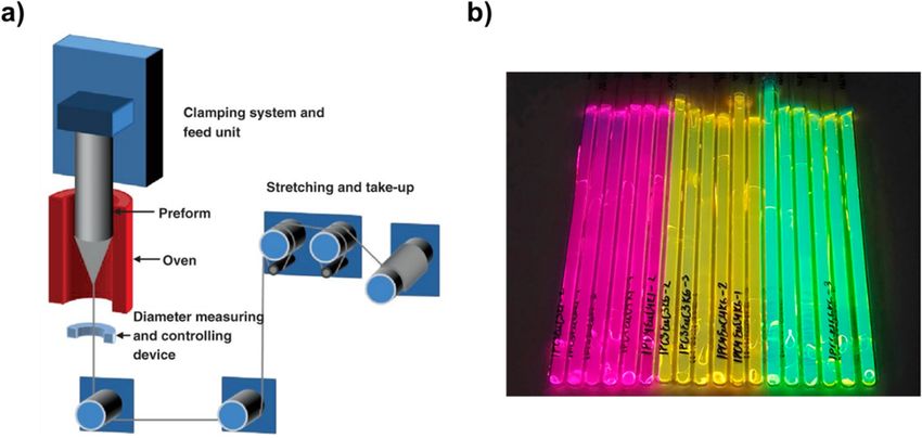
K. Jakubowski et al. Current Opinion in Solid State & Materials Science 25 (2021) 100912
Fig. 1. Representation of various processes that take place upon light absorption by a luminophore. Green arrows represent variants of fluorescent emission and the
red arrow is a phosphorescent emission, which can be significantly delayed due to the extended lifetime of excited state(s). (For interpretation of the references to
color in this figure legend, the reader is referred to the web version of this article.)
2. Basics of PL-POFs dispersed within the fiber material. Due to its internal placement, the
dye emits much of the light within the fiber’s acceptance cone, thus
Like POFs, PL-POFs utilize the principle of total internal reflection enabling sidewise light collection. PL-POFs are hence prone to perform
(TIR) [6] for wave guiding: below a critical angle, the light rays traveling well in sensing or light collection/distribution over relatively short
within a high refractive index (RI) medium are reflected at the optical distance.
interface with a second low-RI material. In the waveguide, light rays Apart from a suitable RI step, the choice of polymeric materials for
may undergo numerous reflections. In the simplest configuration, the PL-POFs must include compatibility with the dye and the processing
low-RI material is air (core-only fiber), with RIair ≈ 1.00. The best conditions [23,24]:
known polymeric example is PMMA, which has RIPMMA ≈ 1.49 [7];
polycarbonates (PC) have RIPC ≈ 1.58 [7], polystyrene (PS) RIPS ≈ 1.58 • The core polymer must be transparent, to facilitate transmission of
[7] and cyclo-olefin polymers (COP) RICOP ≈ 1.53 [8]. In a bi- light.
component core-cladding fiber, the high-RI polymer core is coated • The polymers have to enable melt spinning of fibers with good me
with a low-RI cladding, providing both robustness of the optical prop chanical properties.
erties and beneficial mechanical behavior [6,9]. • The compatibility of core, cladding and dye material must allow for
Typically, low-RI polymers are fluorinated polymers, such as poly reproducible co-processing.
tetrafluoroethylene (PTFE) or terpolymer of tetrafluoroethylene, hexa
fluoropropylene and vinylidene fluoride (THV), exhibiting RI values as Most of the polymers used for PL-POF production are amorphous,
low as 1.34 [10]. In some studies, a low-RI polymer capillary was filled since crystalline regions promote light scattering due to a small RI dif
with a high RI liquid, resulting in a liquid-core optical fiber [11–16]. A ference between crystalline and amorphous phase [21], especially when
desired characteristic of fibrous materials is high flexibility, and thus present in the core material.
alternative polymers like polydimethylsiloxane (PDMS) have been used PL-POFs are obtained by doping a waveguiding polymer with a
[17–19], but upscaling of respective POFs revealed certain application luminophore, i.e. a dye that exhibits photoluminescence, which is a
limits: the low RI of PDMS (RIPDMS ≈ 1.41) [20] implicates a small nu process of light emission that occurs from electronically excited states.
merical aperture (NA), which diminishes the fiber’s light acceptance Depending on their nature, PL can be divided into two categories:
cone [21], therefore restricting its capability to capture and transmit fluorescence and phosphorescence [25]. A common way to illustrate
luminescent light in PL-POFs [22]. Above list of polymers represents a these and other accompanying processes is the Jablonski diagram [26],
selection, since many other materials have been investigated as base shown in Fig. 1.
materials for POFs, and thereby also for PL-POFs [7,23]. An electron typically exists in a singlet, ground electronic state (S0).
The optical acceptance cone defines the highest TIR angle at which A photon of energy equal to or greater than the energy gap between this
the light can enter the core at its end (tip); a higher step difference be state and a singlet excited state (Si) interacts with the electron, trans
tween the RIs of the two materials leads to higher acceptance angles. ferring its energy in a process of absorption. As a result, the electron is
POFs do not couple sidelong incoming light. However, the presence of excited, usually to one of the higher vibrational levels of an excited state.
optical imperfections, such as light-scattering impurities or cracks, can From there, it undergoes a fast, vibrational relaxation to the lowest
couple light in or out of wave guiding modes. While this effect is pur energy state of the given excited state. If the energy of the incoming
posely used in periodic grating couplers or sensor fibers, side-coupling of photon is high, and the electron is in an upper excited singlet state ≥S2,
light is disadvantageous in long-range telecommunication. PL-POFs it undergoes a fast relaxation to the first excited state (S1) in a process
allow a controlled degree of side-coupling via photoluminescent dye, called internal conversion. From there, the electron can either undergo
2
K. Jakubowski et al. Current Opinion in Solid State & Materials Science 25 (2021) 100912
Fig. 3. Principle of operation of a PL-POF. External light, approaching the
device from the side, is absorbed by dye molecules and undergoes a light-
conversion process, during which it is emitted within the fiber acceptance
cone. The in-cone portion of the converted light is guided to the end (fiber tip),
Fig. 2. Example of absorption (black curve) and emission (red curve) spectra of where it can illuminate a solar cell, a spectrometer, or any other suitable de
a luminescent material, Rhodamine 6G. Stokes shift and the resulting overlap tector. Reproduced with permission from Ref. [41].
between the two curves are indicated. (For interpretation of the references to
color in this figure legend, the reader is referred to the web version of harvesting. In general, organic dyes exhibit relatively small Stokes shifts
this article.) (typically less than 50 nm), as a result of their rather high exciton
binding energy. This means that self-absorption is amplified, which
another internal conversion to the ground electronic state (S0) without limits the practicable dye concentration.
emitting a photon, or it can undergo a process of fluorescence, where a The Wannier-Mott exciton occurs in inorganic materials, where the
photon is released. The exact energy of the emitted photon is equal to the binding energy is lower (in the order of 0.01 eV) and the exciton radius is
difference between the energies of the final vibrational level of the larger. Among luminescent inorganic materials, ion-based phosphors
ground electronic state and the first excited state. On rare occasions, the and semiconductor quantum dots (QDs) are the best-known examples.
electron can undergo a spin conversion from the first singlet excited Among ion-based phosphors, the rare-earth-based organic-inorganic
state to the first triplet excited state in an intersystem crossing process. hybrid lanthanide ions (Ln3+) [34] are the most popular. Absorption
From there, similar relaxation pathways exist, and the respective photon arises mainly from coordination with organic ligands, and the emission
emission is called phosphorescence. The timescales associated with is controlled by the intrinsic f-f transition of lanthanide ions, yielding a
these phenomena are longer compared to fluorescence – they are called large Stokes shift. As for the semiconductor QDs [35] consisting of
“forbidden transitions”, which means that they occur at much lower nanocrystals with several nanometer sizes, the main factors controlling
rates [27]. the absorption and emission are the particle size and the intrinsic de
As a consequence of above processes, three distinct characteristics of generacy states of the material. Smaller QDs tend to generate blue-
photoluminescence arise: Stokes shift, quantum yield (QY) and fluo shifted emission and absorption due to highly localized states (Dirac
rescence lifetime [28]. The Stokes shift is the difference between en distribution)—similar to a dot. The physics of large QDs are more of a
ergies (or wavelengths) of absorbed and emitted photon. Since the three-dimensional nature, therefore bands tend to be continuous and
electron undergoes relaxations without emission (vibrational relaxation, give rise to red-shifted emission and absorption. The nano-material-
internal conversion), the energy of emission is lower than that of the inherent size-dependence provides a conveniently adjustable range of
excitation light. When photons are also emitted in the luminescent QD-based luminescence. A more detailed description of photo
material’s absorption range, absorption and emission spectra can over luminescent processes is beyond the scope of this review, and we thus
lap: in waveguides, this results in a prevalent self-absorption problem of refer to a respective book by Lakowicz [36].
the emitted light. Stokes shift and the spectral overlap are schematically Different classes of suitable dyes are available, such as organic dyes,
illustrated in Fig. 2. QY is a ratio of the number of emitted to absorbed nanomaterials, or rare-earth complexes [37–40]. In general, a suitable
photons. The fluorescence lifetime is the average time, which an elec photoluminescent dye must meet following additional criteria:
tron remains in the excited state. Usually, fluorescent molecules have
lifetimes of several nanoseconds. • The dye has to disperse well in the selected polymer(s) [23,41], since
In condensed matter theory, a quasiparticle called exciton [29–31] is aggregation of dye molecules can lead to excessive optical absorption
responsible for luminescence. Excitons are electrostatically coupled and and quenching [42].
overall electrically neutral electron-hole pairs, created when an electron • The dye absorption/emission spectra should have minimal overlap
is excited. They can be categorized into two types: Frenkel [32] exciton and should be appropriate for the lighting/detector conditions.
and Wannier-Mott [33] exciton. A Frenkel exciton has higher binding • Processing stability and lifetime of the dye must enable long-term
energy, i.e. energy required to excite the electron, of 0.1–1 eV, a smaller applications.
exciton radius, and it appears mainly in organic materials. The most
common examples are π-conjugated organic dyes like rhodamines, A schematic representation of the PL-POF’s operation principle,
coumarins, perylene, and perylene bismides. Especially rhodamine dyes illustrating side coupling followed by in-cone emission and wave guid
are known to exhibit high QY and high molar-excitation efficiency. ing to the fiber tip, is shown in Fig. 3.
However, the small Stokes shift and low photostability of rhodamine As derived by Muto [43] for glass fibers, the total PL intensity
limits its use for long-term applications. For coumarin dyes, the Stokes generated by a PL fiber of a given length depends on several parameters:
shift is larger, the photostability is better, and the QY is rather high. On
the other hand, the emission of coumarin dyes lies in a relatively high • The radiant flux of excitation light illuminating the fiber side surface.
energy range, which limits their application for biomaterials and energy • The transmissivity of the fiber side surface.
3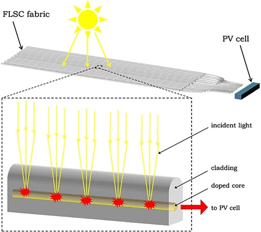
K. Jakubowski et al. Current Opinion in Solid State & Materials Science 25 (2021) 100912
Fig. 4. Schematic illustration of the main effects
influencing the efficiency of light conversion and
propagation in a PL-POF: a) Fresnel reflection from
interfaces between two media. b) Loss emission at
angles exceeding the trapping angle. c) Emission
trapped within PL-POF. d) Self-absorption with re-
emission in loss angles, i.e. either opposite to the
end device or at angles exceeding the trapping angle.
e) Self-absorption with re-emission within the trap
ping angle. f) Self-absorption without re-emission due
to non-unity QY. g) Cascade of self-absorptions with
re-emission of less-energetic light due to Stokes effi
ciency. h) Loss of intensity of emitted light due to
background absorption by the polymer or by scat
tering. For clarity, effects due to multiple Fresnel re
flections are not shown.
• The conversion efficiency, relating the radiant flux of the wave The factor ηabs represents the spectrum-integral absorption efficiency
guided luminescent light to the flux of excitation light. of the dye for a given incident illumination spectrum [46]:
• The transmission loss of the PL-POF. dye
EG
∫
S(λ)A(λ)dλ
To assess the PL-POF system performance, a property known as
ηabs = 300
(4)
“optical conversion efficiency”, ηopt , is utilized, which also accounts for ∫∞
S(λ)dλ
propagation losses. It is defined as the photoluminescence fiber tip 300
output power (Pout) divided by the power of side surface illumination
(Pin), and can be written as a product [44,45]: where S(λ) is the incident photon flux spectrum, ELum
G is the bandgap of
the luminophore in nm, and A(λ) is the absorption spectrum of the
Pout
ηopt = = (1 − R) × ηabs × ηStokes × ηQ × ηtrapping × ηtransport × ηself (1) luminophore, according to the Beer-Lambert law [47]:
Pin
A(λ) = 1 − 10− α(λ)∙c∙l
(5)
where R is the reflection coefficient from the surface of the fiber, ηabs is
the dye absorption efficiency of the incoming side illumination, ηStokes is Here, α(λ) is the wavelength-dependent absorption coefficient, l is the
the energy loss factor related to the Stokes shift, ηQ is the QY of the dye, effective light propagation length, and c is the concentration of the
ηtrapping is the trapping efficiency (viz. acceptance cone) of light re- photoluminescent dye.
emitted into the waveguide, ηtransport is the efficiency of the light prop Furthermore, ηStokes in Equation (1) is the energy down-shift factor
agation and ηself is the efficiency factor relating to repeated self- connecting to the longer wavelength of emitted light in luminescence.
absorption of converted light by other dye molecules. The factors in Mathematically, this is the ratio between the averaged (i.e. spectrum
Equation (1) depend on the properties of dye and polymers used, as well center-of-gravity) energy of emitted photons and the averaged energy of
as on the geometry of the luminescent solar concentrator; their quali absorbed photons in the down-conversion process. Therefore, ηStokes is
tative understanding is crucial for optimizing device efficiency. Note normally smaller than one:
worthy, all of the aforementioned parameters are wavelength- λabsorbed
dependent. ηStokes =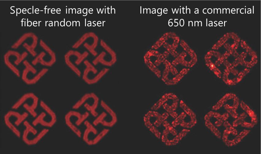
K. Jakubowski et al. Current Opinion in Solid State & Materials Science 25 (2021) 100912
Fig. 5. Schematics of a fiber-based light concentrator setup. A textile structure of PL-POFs covers a large area, collecting sunlight via side illumination and light-
conversion; radiative energy is guided towards a small-sized PV cell at the end. Reproduced with permission from Ref. [45].
the acceptance cone of the wave guide. Mathematically, the acceptance processes that impact light traveling within PL-POFs. The end device can
cone in a cylindrical geometry can be expressed with the following be a detector, a PV cell, or something else that fits the intended
equation [53]: application.
√̅̅̅̅̅̅̅̅̅̅̅̅̅̅̅̅̅̅̅̅̅̅̅̅̅̅̅̅̅̅̅
( )2
ncladding 3. PL-POFs used as solar light concentrators
ηtrapping = 1 − (8)
ncore
Currently, the best performing photovoltaic (PV) cells are reported to
where ncl and nco are the refractive indices of cladding and core, reach efficiencies around 40% under ideal laboratory conditions, while
respectively. Equation (8) is identical to the often-cited equation for established PV cells just exceed 20% [59]. The conventional strategy to
trapping efficiency in planar waveguides of rectangular cross-section. In increase solar energy production is to increase the area covered by PV
contrast to the latter, as shown by McIntosh et al. [22], light emitted cells, at a proportional increase of costs [60]. Luminescent solar con
from molecules dispersed in a cylindrical fiber experiences a range of centrators (LSCs) can enhance energy production via a different
trapping efficiencies which depends on the emitting molecule’s distance approach, as first proposed in the 1970s [61–64]. Today, the work on
from the optical interface defining the acceptance cone. LSCs is largely dominated by planar slab waveguide approaches
Finally, in Equation (1), ηself considers the losses in the carried power [65–67]. Less attention is given to PL-POFs, although they come with a
due to repeated self-absorption of the emitted light by other luminescent number of benefits, such as light-weight, flexibility, as well as the
centers. In analogy to Equation (4), a self-absorption probability can be availability of established large scale manufacturing and processing
expressed as follows: techniques [68]. For LSC applications, a PL-POF has to be optimized to
dye
deliver maximal optical power near the maximum efficient wavelength
of the PV cell. The PV enhancement with/without LSC can be described
EG
∫
Sdye (λ)A(λ)dλ
with a LSC-gain factor F [69,70], which is defined as the ratio of power
(9)
300
Pre− =
absorption ∫∞ generated by a solar cell with LSC (PLSC), to the power generated by the
Sdye (λ)dλ
300 cell alone (Pcell):
PLSC
where Sdye (λ) is the emission spectrum of the dye. A more detailed study F= = ηopt × G × ηcell (10)
Pcell
of self-absorption can be found in the supplementary information of
[54,55]. Once the light undergoes a self-absorption process, it is sus where ηopt is the optical conversion efficiency of the LSC (see Equation
ceptible to all the aforementioned loss mechanisms [50,56] (apart from (1) for PL-POF), and ηcell is the efficiency of the PV cell. G is a geometrical
Fresnel reflections). It has been shown [57,58] that luminescent light of gain factor pertaining to the concentration of light from the larger col
wavelength in the dye’s absorption range, propagating inside a PL-POF, lector area to the smaller PV area; it is analogous to an improvement of
is attenuated orders of magnitude stronger than light outside of this the photon capture area, calculated as the ratio between total light-
range. harvesting area of the LSC (Acollection ) and the PV cell area (Aoutput ):
To conclude this section, Fig. 4 illustrates schematically various
5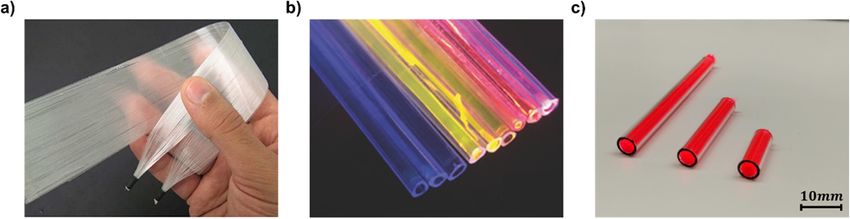
K. Jakubowski et al. Current Opinion in Solid State & Materials Science 25 (2021) 100912
Fig. 6. a) A solar-light harvesting textile based on shape-optimized fiber LSCs. Reproduced with permission from Ref. [45]. b) Bundle of liquid-core triangular fibers
with three different dyes under UV light illumination. Reproduced with permission from Ref. [85]. c) Photography of PL-POF bundles within PMMA tube. Repro
duced with permission from Ref. [41].
G = Acollection /Aoutput (11) explored the double-doping approach, showing the impact of the fiber
diameter on the LSC performance: when the output power is relevant,
A schematic illustration of an LSC based on PL-POFs is presented in
fibers should have larger diameter; on the other hand, when the output
Fig. 5, where the importance of a large G-factor is obvious. Fig. 6a de
irradiance is of importance, smaller fibers are advantageous [84].
picts the respective light harvesting textile.
Correia et al. [69] presented two original geometries of fiber LSCs:
The approach utilizing luminescent concentrators has two additional
fibers coated with a luminescent layer, and hollow-core fibers filled with
advantages over passive systems like mirrors or lenses:
an active luminescent fluid. The second approach proved to have higher
trapping efficiency, mainly due to the higher refractive index step. The
• The down-conversion of light renders LSCs more suitable for PV cells,
latter design also proved to be optically more robust, since the polymeric
since panels interact best with a light of energy close to their band-
sheath surrounding the core acted as protective layer, preventing me
gap [44,71].
chanical damage in the waveguiding element. The group later expanded
• Luminescent conversion erases the information about the angle of
the idea towards hollow-core triangular fibers, filled with the same
incidence of the excitation light by the process of re-emission, thus
active material, and bundled together into a planar structure (Fig. 6b)
alleviating the limitation of passive concentrators [72,73], which
[85].
collect light only within the limits of the etendue [74–77]. In lumi
A theoretical investigation by Videira et al. [86] demonstrated that
nescent solar concentrators, where incoming light is converted by
cylindrical arrays of LSCs outperform planar LSC waveguides, thanks to
the dye and emitted within a waveguide, the etendue is redefined,
multiple reflections, lensing, and tailored shadowing between adjacent
enabling a large field of view.
fibers. LSC fiber bundles were also used by Galatus et al. [87] to extend
the battery lifetime of a remote sensor device. Similar bundles, based on
Work on PL-POFs includes different aspects of optimization of the
an up-scalable melt-spinning production approach, were studied by
LSC gain factor F. Wu et al. [55] performed a detailed analysis of self-
Jakubowski et al. [41]. This study focused on eliminating the solar
absorption utilizing a rare-earth complex with large Stokes shift to
midday peak, which relates to the dependence of PV power generation
obtain PMMA-based fibers that are quasi free of self-absorption. Inman
from the incidence angle α of solar light. When considering fiber bundle
et al. [78] presented hollow-core PMMA-fibers doped with QDs emitting
LSCs, Equation (1), describing optical conversion efficiency, can be
in the near-infrared region, claiming that such structures allow for better
written as:
excitation absorption and lower self-absorption, since light is propa
gating in the air while maintaining a similarly high G-factor. Pout (α) Iout (α) × Aout
ηopt (α) = = (12)
Banaei et al. [79] designed a fibrous LSC, based on a dye-doped COP Pin (α) Iin × Acollection (α)
core and a custom-shaped COP cladding. The shape of the cladding was
optimized to unidirectionally focus the incoming excitation radiation where Pout(α) and Pin(α) are effective output and input powers, Iout(α)
onto the core, thus enhancing the overall performance. Another struc and Iin are output and input flux intensities, and Aout and Acollection(α) are
ture of a shape-optimized fiber-based LSC consisted of an undoped COP effective emitting and collecting areas, respectively. The mentioned
cladding surrounding a luminescent-doped PC core [45]. This study also angular dependency stems from an effective change of Acollection: at
demonstrated the beneficial influence of a reflective side surface of the shallow angles, the incoming light is received by a larger projected area
fiber LSC, placed opposite to the light source; a respective enhancement of the vertically positioned LSC bundle. Fig. 6c shows the fiber bundles
was already predicted by Edelenbosch et al. [80] with ray-tracing prepared in this study. Recently, Besida et al. [88] presented a fiber LSC
methods. The approach with specially shaped fibers is rather complex, with photonic crystal cladding, which enables excitation light to enter
since it requires careful manual assembly for correct orientation of in the fiber, while preventing emitted light to escape at angles exceeding
dividual fibers. the TIR requirements.
Parola et al. [81] showed that, by co-doping a fiber with two Luminescent fibers were also investigated as omnidirectional col
different luminophores, namely a combination of organic dyes and lectors in free-space optical communication [89]. Like stratified LSCs,
metal-organic material, it is possible to expand the harvesting spectral they allow collecting electromagnetic signals from a large area and room
range by increasing the overall width of the PL-POF absorption spectrum angle, using arrays of fibers, thus improving the minimal signal-to-noise
and thus create a more efficient LSC. By monitoring power production ratio (SNR). Peyronel et al. [90] studied commercial fibers mounted in a
over extended periods, they also found that after the initial, fast emis detector setup with an active area of 126 cm2, achieving data rates up to
sion intensity decay, the performance of their best device reached a 2.1 Gb/s with a safety conform emitter intensity. Along similar lines,
plateau at 64% of the starting value when exceeding 600 h of illumi Riaz et al. [91,92] investigated PL-POFs as a way to improve Wi-Fi
nation. Interestingly, fibers doped with a single organic dye showed no networks for indoor applications. They demonstrated an increase of
significant initial decrease over the first several hours of exposure, as has data capacity of a communication channel by augmenting its SNR,
been observed for double-doped fibers [82,83]. The group further achieved by enlarging the light collection area.
6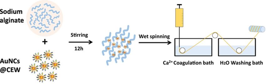
K. Jakubowski et al. Current Opinion in Solid State & Materials Science 25 (2021) 100912
Table 1 Long-term stability has been recognized as a factor limiting the out
Overview of PL-POFs for electromagnetic radiation harvesting. The active sys door application of LSCs prepared with organic light-converting dyes. A
tem refers to the luminophore or a combination of luminophores used in the regular replacement of the devices would be required when their per
study. In the case of concentration-dependent surveys for one fiber geometry, formance deteriorates due to dye degradation [98–100]. However,
only the best results are shown. Slooff et al. [101] have shown that the outdoor stability of LSC plates can
Fiber Active dye system Maximal ηopt (LSCs), Ref. be improved by a proper selection of the host polymer, mainly by
material purpose (signal concentrators) choosing high purity. By utilizing distilled PMMA, as compared to
PMMA Eu(TTA)3Phen metal- Not provided [55] commercial plexiglass containing unreacted monomers, dye degrada
organic complex tion could be significantly reduced. Another approach to improve out
PbS quantum dots 7.5% (hollow fibers) [78] door stability is to replace organic dyes with inorganic QDs – some of
4.0% (solid core fibers) which are recognized to be more stable under constant illumination
Combination of dyes, 0.23% [81] conditions [102]. An additional advantage of QDs is their tunable Stokes
including organic
shift, allowing for reduced self-absorption of the emitted light
perylene derivatives,
coumarines and [103–106], which is a significant loss mechanism, as outlined in Section
metal-organic 2. Using QDs to overcome issues prevalent in LSCs, is gaining more and
complexes more attention in the scientific community, and further information can
Combination of dyes, 0.29% [84]
be found in several comprehensive reviews [38,107,108]. While
including organic
perylene derivatives,
changing the type of luminophore helps to lower the self-absorption, it
coumarines and does never completely remove it, and thus another method to
metal-organic compensate for this effect has been proposed by Krumer et al. [56,104] –
complexes it has been demonstrated, that increased luminophore concentration
Rhodamine 6G- 8.0% (hollow fibers) [69]
counteracts self-absorption in planar LSCs, an approach which could
doped organic- 0.08% (coated fibers)
inorganic hybrids also be explored in PL-POFs in the future.
Eu3+-doped organic- 2.3% (hollow fibers) [69] Table 1 summarizes the PL-POFs for light harvesting, with emphasis
inorganic hybrids 0.01% (coated fibers) on material composition and optical performance. The conversion effi
Rhodamine 6G 1.52% (hollow, triangular [85] ciency listed for fiber LSCs is relatively low, which is caused by the usage
organic dye fibers) of either un-optimized material composition and fiber geometries, or
0.33% (hollow fibers)
0.18% (coated fibers)
systems without appropriate connection between concentrator and PV
Eu3+ complex 1.14%(hollow, triangular [85]
cell. Tackling those challenges by optimizing the design of a fiber
fibers) concentrator, and by creating an optically improved connection, will
0.02% (hollow fibers) eventually allow to achieve higher efficiencies.
0.06% (coated fibers)
PS Unspecified amber Unspecified [87] 4. PL-POFs for sensing applications
dye
Unspecified dye, Increasing the effective area [90]
peak emission and field-of-view of a free- POFs are already widely used as signal guides or transducers in
around 500 nm space optical communication sensor applications [109–111]. Transduction includes converting one
signal receiver type of energy into another, ideally a human readable one. PL-POFs can
COP DCM organic dye 5.7% [79]
readily act as transducers, excited by an incoming radiation of choice (e.
PC (core), Unspecified 7.2% [45]
g. visible light, high-energy radiation, sub-atomic particles, etc.), and
COP luminophore
(sheath)
changing emission characteristics depending on sensed quantities like
COP (core), Lumogen Red From2.0%to15%(angle- [41] external force or presence of an analyte [112]. Therefore, an added
THV organic dye dependent) value of PL-POFs is the simple excitation that often waives the need for a
(sheath) specially engineered light source. From a historical perspective, the first
Unspecified Unspecified Unspecified optical efficiency [88]
application of PL-POF sensors was the detection of ionizing radiation.
Unspecified, green- Increasing the effective area [91,92]
emitting dye and field-of-view of a free- While detection of ionizing radiation was demonstrated with undo
space optical communication ped fibers through the means of Cherenkov radiation [113] or radiation-
signal receiver induced attenuation [114], fibers doped with special molecules are
described as scintillating fibers. Such scintillating fibers (e.g. provided
by Kuraray or Saint-Gobain Crystals) consist of a high-RI, dye-doped
Photoluminescence introduces an upper limitation to maximum
core (e.g. PS), surrounded by a low-RI primary cladding (e.g. PMMA),
rates in data communication, due to a finite lifetime of the excited state,
both coaxially surrounded by a low-RI secondary cladding (e.g. fluori
which is in the range of several nanoseconds [25]. Considering current
nated PMMA). Different types of scintillating dyes can be added to the
data-transfer standards, which require communication frequencies of
polymer matrix [115], many of which are treated as a trade secret.
several GHz, the aforementioned PL property implicates a statistical
Currently, the main focus in this field is directed to the design and as
signal delay. The choice of appropriate dyes for PL-POFs, exhibiting
sembly of scintillating detectors. Here, the aim is to record the flying
short lifetimes of the excited state, is thus crucial in achieving improved
path of elementary particles to determine their energy and identity. In
detectors for higher optical frequencies; in consequence, the develop
one proposed setup, fiber layers are stacked into ribbons; when a particle
ment of respectively improved dyes will be an important future task
passes through such an assembly, it excites scintillation, and the pro
[93].
duced light is then received by a space-resolved detection system,
Fiber light concentrators come with certain form-factor advantages
providing information about the particle path [111,116–120]. In an
over comparable planar devices. While planar waveguides can already
alternative design, optimized for calorimetry, the energy of passing
be found in commercial applications [94–96] and have recognized
particles can be determined [121,122]. This latter design is similar to
future potential [97], additional progress is still required to bring fibers
the above tracker ribbons, but individual fibers (or layers of fibers) are
to a similar level. The required improvement must focus on large-scale
separated by dense absorbers, which repeatedly absorb a known portion
processing of transparent polymers with new dyes, which are charac
of the energy of the passing particles. The resulting emission of sec
terized by prolonged outdoor stability and enhanced light-conversion.
ondary electrons with progressively decreasing energy is then used to
7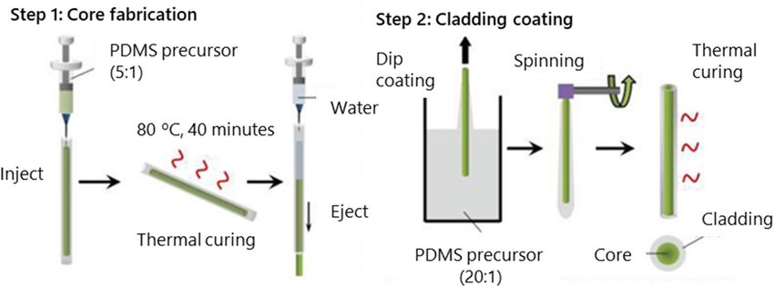
K. Jakubowski et al. Current Opinion in Solid State & Materials Science 25 (2021) 100912
Fig. 7. Demonstration of colorimetric detection of Cu2+ and Hg2+ ions using PL-POFs that change their emission color and intensity when in contact with specific
ions. Reproduced with permission from Ref. [144].
deduce the energy of the passing particle. This second prominent The effect of fluorescent quenching at elevated temperatures can be
application of scintillating POFs is optimized for medical applications, used as a measure of temperature [36], which was also demonstrated
including in-vivo dosimetry [123] and radiology [124]. As was inves experimentally utilizing fibers [141]. The aforementioned group (Guo
tigated by Laguesse and Bourdinaud [125], PL-POFs can be subject to et al.) likewise studied temperature sensing with stretchable fibers,
accelerated aging when irradiated by high-energy (e.g. ionizing) exci resulting in discriminating multi-parameter sensing devices for strain
tation light; both, aging of the polymer and the dye can occur [126,127]. and temperature [140,142]. Here, lanthanide-based up-converting
For more detailed information about the recent progress in scintillating nanoparticles, which exhibit distinctively temperature-sensitive lumi
POFs, we refer to the respective book chapter by Stajanca [128]. nescence peaks at 545 nm and 525 nm, promise a robust measure of
PL-POFs are also used to detect less energetic or non-ionizing radi temperature by calculating the intensity ratio between the two, i.e. I545
ation, such as ultraviolet (UV) or visible radiation. Here, the external nm/I525 nm.
excitation light passes through the PL-POF transducer, inducing lumi Chemical sensing with a luminophore-doped POF core has been
nescence, and creating re-emission of proportional intensity. Fitzpatrick demonstrated by Farago et al. [143], based on the interaction of a se
et al. [129] demonstrated the feasibility of using PL-POFs, consisting of a lective analyte with the luminophore (i.e. via fluorescent quenching),
doped cladding and a waveguiding core, to monitor the intensity of where the cladding was partially removed to expose the core. In a case
high-power UV lamps. Miluski et al. [130], also utilizing a doped clad study, this fiber was put in contact with saliva, and certain fluorescent
ding, studied a UV-A (315–400 nm) fiber sensor. The same group wavelengths were absorbed when blood was present in the solution. He
demonstrated UV-light detection by a uniformly doped PMMA fiber, et al. [144] presented a fluorescent fiber-based sensing platform to
directly analyzing both luminescence intensity and intensity ratios of the detect Cu2+ and Hg2+ ions, where the fluorescence is quenched by the
luminescent emission peaks [131]. Szolga et al. [132] used PL-POFs to ions. Here, the quenching rate can be calibrated to the concentration of
detect plasma emission from switching arcs in electrical distribution the respective ionic species (Fig. 7). Inglev et al. [145] demonstrated
boards; the flexibility of those fibers allowed optimal board integration. localized oxygen sensing based upon undoped POFs, where the lumi
Mahidhar et al. [133] applied fluorescent fibers to monitor discharges in nescent behavior is introduced by splicing two such fibers together using
liquid nitrogen, which occur in electrical power applications of high- a special mixture containing phosphorescent dye. In presence of oxygen,
temperature superconductors. This method gave similar results as the the luminescent intensity of those splices decreases, giving an indication
conventional ultrahigh-frequency method, indicating the yet unex of its concentration.
plored potential of PL-POFs in this field. A noteworthy family of chemical PL sensors is represented in the
A common sensing principle is based on the fact that PL-POF form of nanofiber-based photosensitive membranes. Although they have
waveguiding is affected by the geometry of optics, such as bending no waveguiding properties like PL-POFs, these devices offer a fiber
angle, pressure, elongation, or simply the distance between illumination platform for analytes detection, based on changes in their PL charac
position and fiber tip. Recently, PL-POFs were used as bending sensors teristics, as illustrated by the following examples. Wang et al. [146]
[134,135], since bending leads to local leakage of light, when a portion prepared nanofiber membranes populated with well-tuned perovskite
of the guided light no longer obeys TIR. Along the same line, PL-POFs QDs, used to detect Rhodamine 6G dye in aqueous and ethanol solutions
were also employed as proximity sensors [136]. By varying the posi down to 0.01 ppm. Since the absorption of rhodamine optimally over
tion of the side-illumination along the PL-POF’s longitudinal axis, the laps with the emission of the QDs, amplified energy transfer between the
emission intensity changes as a function of varying attenuation. Proper two can occur, greatly enhancing the emission of Rhodamine 6G for
calibration assumed, such propagation losses can be used to calculate detection. Hu et al. [147] demonstrated a reversible and photo-stable
how far from the fiber tip the excitation process took place. This HCl gas sensor based on porphyrin-doped porous nanofibers, where
approach may aid in facilitating precise alignment [137,138]. the analyte acts as a fluorescence quenching agent, with quenching ki
For pressure sensing, Kamimura et al. [139] utilized fibers contain netics proportional to the HCl concentration. Shu et al. [148] prepared
ing two different luminescent dyes, one in the core and one in the polyethylene terephthalate (PET) nanofiber membranes, which change
cladding: when pressure is applied on the fiber, light emitted by the dye their luminescence in oil vapor; when oil is adsorbed on the surface of
in the core leaks to the cladding, where it is specifically absorbed by the the membrane, it absorbs the excitation light, which otherwise would
other luminophore. Recently, Guo et al. [140] demonstrated stretchable excite the luminescent nanofibers, hence it reduces the emission in
PL-POFs based on PDMS to detect strain: upon elongation, the light tensity. The group also demonstrated a possibility to de-oil the structure
travels a longer path within the fiber and is accordingly more absorbed. and reset the measuring device. Hsu et al. [149] presented a fiber
As shown by Jakubowski et al. [58], strain sensing can also be per membrane tailored to detect ammonia down to a concentration of 110
formed using POFs with a liquid glycerol core doped with luminophore. ppb, with the potential of re-using it up to six times after washing.
Here, elongation was detected by measuring the shift of the lumines Petropoulou et al. [150] demonstrated another approach to ammonia
cence peak caused by the dye self-absorption; the use of liquid-core fi gas sensing, based on natural cellulose nanofibers. Thanks to the large
bers, featuring a semi-crystalline sheath, enabled reversible and surface-to-volume ratio of the substrate, a concentration of up to 1.2% of
irreversible strain detection of up to 10% and 350%, respectively. ammonia could be detected in aquatic solutions, with good linearity
8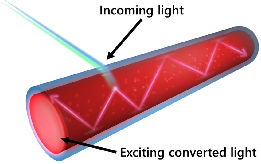
K. Jakubowski et al. Current Opinion in Solid State & Materials Science 25 (2021) 100912
Table 2
Overview of PL-POFs for sensing. The active system refers to the luminophore or a combination of luminophores used in the study.
Fiber material Active system Sensing mechanism Ref.
PMMA Europium complex Detection of UV light based on excitation dose variation [131]
Coumarin 540A (in the core), Rhodamine Pressure sensing by changes in the energy transfer between the two dyes [139]
6G (in the cladding)
Rhodamine B Temperature sensing via fluorescence quenching [141]
Platinum Octaethylporphyrin Oxygen concentration sensing via phosphorescence quenching [145]
PMMA (core), polyurethane Tinopal Detection of UV-A radiation based on excitation dose variation [130]
(sheath)
PS Unspecified green dye Partial discharge in liquid nitrogen detection based on excitation dose variation [133]
Unspecified dye, peak emission around Bending angle determination by the variation in PL intensity [134,135]
450 nm.
Unspecified dye, peak emission around Illumination-position determination by the variation in PL intensity [136]
660 nm.
Unspecified dye, peak emission around Illumination-position determination by the variation in PL intensity [137]
540 nm.
Unspecified dye, peak emission around
645 nm.
Unspecified dye, peak emission around Detection of blood in saliva by emitted light absorption [143]
450 nm.
CsPbBr3 quantum dots Rhodamine 6G detection in aqueous media via energy transfer [146]
5,10,15,20-tetraphenylporphyrin HCl detection by fluorescence quenching by the analyte [147]
PS (core), vinyl acetate (sheath) Unspecified dye X and gamma radiation detection based on excitation dose variation [125]
PS (core), fluorinated PMMA Unspecified dye X and gamma radiation detection based on excitation dose variation [125]
(sheath)
Glycerol (core), THV (sheath) Rhodamine 6G Strain sensing by measuring the emission peak shift caused by self-absorption of the [58]
dye
PDMS Lanthanide-based upconverting Strain sensing based on the increased attenuation upon elongation. Temperature [140,142]
nanoparticles sensing based on changing the emission intensity of the luminescent system
PET p-Methylbenzoic acid terbium complex Oil detection by covering the luminescent nanofibers, thus preventing excitation [148]
Alginate Red-emitting gold nanoclusters Detection of heavy ions based on fluorescence quenching [144]
Poly(vinylidene fluoride-co- Carbon dots with fluorescein Repeatable ammonia detection down to 110 ppb. [149]
hexafluoropropene)
Cellulose acetate Core-shell γ-Fe2O3/SiO2/Rhodamine B Ammonia detection via fluorescence quenching by the analyte [150]
nanoparticles
Unspecified Unspecified red and green phosphors Detection of the UV-light based on excitation dose variation [129]
Unspecified red dye Arc and flame detection based on excitation dose variation [132]
Unspecified yellow dye Illumination-position determination by the variation in PL intensity [138]
Cyano-substituted vinylacridine Aromatic amines and acid vapors detection via fluorescence quenching by the [151]
derivatives analytes
over a wide range of pH, until optical quenching became too strong. Xue membranes as stretchable, moisture-resistant covers for blue LEDs, thus
et al. [151] utilized gel nanofibers as host material to enable quenching extending the lifetime of white light emitters under ambient air condi
of aggregation-induced emission, and applied them for the detection of tions. A rare approach using phosphorescence was presented by Luo
aromatic amines and acid vapors, with detection limits of 1.3 μg/m3 and et al. [156], where the PL-POFs exhibited a persistent afterglow after
2.3 mg/m3, respectively. excitation stopped.
A summary of the aforementioned PL-POFs proposed for sensing As already demonstrated two decades ago [157], PL-POFs can also
applications is given in Table 2, with emphasis on material composition function as so-called “random lasers” [158–160], where the required
and sensing mechanism. energy feedback mechanism is provided by random scattering at parti
cles embedded in the PL-POF matrix. This feedback is in contrast to
5. PL-POFs for special applications conventional Fabry-Perot cavities [161] or distributed feedback lasers
[162,163]. However, with high enough pump energy (called “pump
Although PL-POFs mainly attracted attention as light harvesters and threshold”), lasing can be obtained, which provides speckle-free laser
sensing probes, recently several other noteworthy applications emerged. illumination for imaging [164–166], as shown in Fig. 8.
He et al. [144] described a novel type of PL-POFs to be used as Table 3 highlights some recent advances in the use of PL-POFs as
fluorescent anti-counterfeiting elements when stitched into cotton tex anti-counterfeiting agents, illumination systems, random lasers, or op
tiles; these fibers provide means of identification under UV-light illu tical communication signal detectors.
mination. A similar approach, based on weaving PL-POFs into fabrics,
was presented by Ding et al. [18], where stretchable fibers can be uti 6. PL-POF production methods
lized as aesthetically appealing decoration elements. Recently, Erdman
et al. [152] prepared luminescent cellulose fibers, which can be incor There are several standard POF production methods [167,168] that
porated into paper to produce documents and banknotes that impede can be adopted for the preparation of photoluminescent fibers, simply
counterfeiting. by adding luminophore at a suitable stage of production. Table 4 sum
In the field of optical fiber lightening technology, Miluski et al. [153] marizes the production techniques proposed by aforementioned
demonstrated the suitability of PL-POFs, employing double-doped fibers publications.
that emit spectrally broad, visible light upon UV-excitation. Cennamo While the first two methods listed in Table 4 are discontinuous, the
et al. [154] used red and blue PL-POFs as portable ambient light sources others can operate in a (semi-)continuous mode, provided that the ma
to excite a surface plasmon resonance (SPR) in biosensing, which suc terial is constantly supplied.
cessfully lowered cost and complexity of the setup, rendering powered
halogen lamps unnecessary. Lin et al. [155] presented nanofiber
9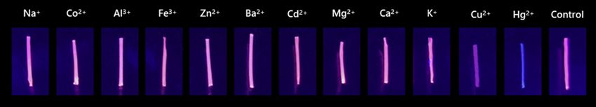
K. Jakubowski et al. Current Opinion in Solid State & Materials Science 25 (2021) 100912
Fig. 8. Optical images of the Hong Kong Polytechnic University logo mask, back-illuminated by PL-POF based laser and 650 nm commercial laser. Reproduced with
permission from Ref. [145].
Table 3
Overview of PL-POFs proposed for anti-counterfeiting, as light sources or random lasers. The active system refers to the luminophore or a combination of luminophores
used in the study.
Fiber material Active system Application Ref.
Alginate Red-emitting gold nanoclusters. Anit-counterfeiting, allowing a simple way [144]
to identify textiles.
Polypropylene Sr2MgSi2O7:Eu2+,Dy3+ phosphor Fibers exhibiting luminescent afterglow [156]
PDMS Three tetraphenylethylene (TPE)-derivatives, with blue, green, Decorative yarns with potential to assist in [18]
and yellow emission characteristics. anti-counterfeiting
Cellulose Star-shaped poly((9-carbazolyl)methylthiirane) Document and banknote anti-counterfeiting [152]
PMMA Perylene and Rhodamine 6G White light (ca. 3350 K) illuminator under [153]
405 nm excitation.
PS Unspecified dyes, peak emission around 660 nm and 450–500 nm. Light source (alternative to halogen lamps) [154]
for plasmonic sensing.
Poly(styrene–butadienestyrene) Cesium lead halide perovskite nanocrystals Luminescent, water-resistant covers for LEDs [155]
Poly(methyl methacrylate-co-benzyl methacrylate) Pyrromethene 597 and gold nanoparticles Random lasing arising from the waveguide- [158]
plasmon-scattering.
Polyhedral oligomeric silsesquioxanes (POSS) nanoparticles and Random lasing [159]
Pyrromethene 597
Fe3O4/SiO2 nanoparticles and Pyrromethene 597 Random lasing [159]
Poly(methylmethacrylate-co-benzylmethacrylate- Pyrromethene 597 Random lasing [159]
co-methacrylisobutyl) Rh640 perchlorate-dye with titanium oxide nanoparticles Random lasing [160]
6.1. Polymerization and curing
Table 4
Overview of PL-POF production methods proposed.
In POF production via polymerization, a mixture containing the host
matrix as a monomer and a curing initiator is injected into a silicon Method Ref.
mold. To manufacture PL-POFs, the educts can readily be doped with Polymerization and [78,131,140,142]
luminescent dyes prior to curing. During the process, the host polymer curing
Thermal drawing [45,55,69,79,81,82,84,85,88,130,131,139,141,153,158,160]
chains are cross-linked, resulting in a stable fiber structure (Fig. 9).
Wet-spinning [18,144,152]
Depending on the base material, curing can be initiated by UV light or Electrospinning [146,149,147,148,150,155,151]
temperature. The resulting fiber is detached from the mold either by and gelation
breaking the latter, or by applying mechanical force (e.g. water stream). Co-extrusion and [41,58,156]
In a second step, the core-only fiber can be coated with a low-RI cladding melt-spinning
material in a dip-coating process, creating a core-cladding POF.
This process of polymerization and curing is rather time-consuming, 6.2. Thermal drawing
and the maximum length of the mold is limited, both because of
manufacturing constraints and restricted feasibility to detach the fiber. Thermal drawing has been widely used in the optical fiber industry
Although this method is not industrially scalable, it is popular at the to produce fiber-like waveguides from glass and polymers alike. Thermal
academic laboratory scale [17,18,169–175], since it does not require drawing is actually the most common way to produce photoluminescent
specialized machinery. fibers (Table 4). It owes its popularity to a large flexibility in cross
Polymerization can be one of the techniques used to produce pre sectional composition and the possibility to produce very long uniform
forms for the thermal drawing process described in Section 6.4. fibers at drawing rates around 0.5 m/s [168]. Thermal drawing is a
batch-process and essentially consists of two steps (Fig. 10a):
10K. Jakubowski et al. Current Opinion in Solid State & Materials Science 25 (2021) 100912
Fig. 9. Schematic representation of the polymerization and curing process to produce POFs. A polymer precursor with a reaction initiator is inserted into a mold,
which is removed after the reaction is complete. In a second step, a low-RI coating is applied via dip-coating. Reproduced with permission from Ref. [128].
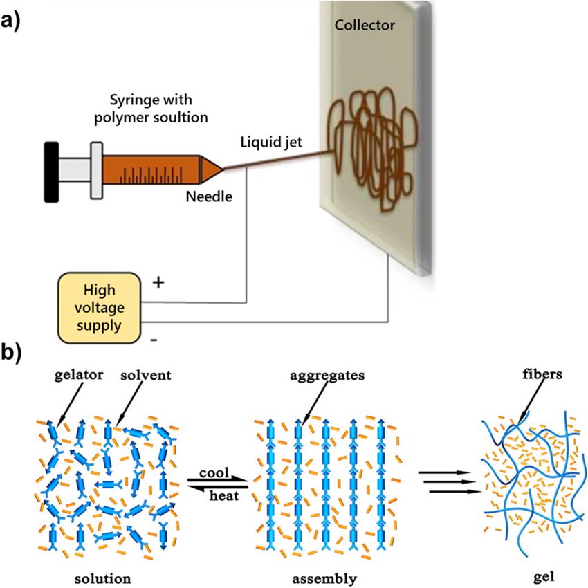
Fig. 10. a) Schematic of a drawing process: a preform is clamped in the feed unit, and its bottom is heated above the base material’s glass transition temperature. The
tapering tip of the preform is finally pulled and stretched by godets to form a fiber. Reproduced with permission from Ref. [168]. b) Photoluminescent preforms
prepared via polymerization, where the luminescent dye was added to the monomer prior to the polymerization. The photograph is taken under illumination with UV
light. Reproduced with permission from Ref. [81].
• Preparation of a preform. possibility to combine different materials in a preform, and thus in the
• Drawing the preform into a fiber. resulting fiber, opens up a multitude of novel applications, e.g. by
combining optical, electrical, or magnetic properties within a single
The preform can be manufactured in a variety of ways, including fiber [176–182].
additive or subtractive manufacturing, molding, polymerization or
extrusion. The cross-sectional shape of the preform is preserved during 6.3. Wet-spinning
fiber drawing, enabling for example hollow-core, microstructured or
triangular fibers. To add photoluminescent properties, the host polymer Wet-spinning is the oldest man-made fiber process; the first report
can be doped with a luminophore during preform preparation as dates back to 1883, where filaments have been produced for light bulbs
required (Fig. 10b). The preform is fixed in the drawing machine by a [183]. In this process, which already became commercial in 1897 for
clamping system and heated up above the host material’s glass transi rayon yarn production, a polymer solution is drawn from a spinneret
tion temperature, thus lowering its viscosity. The tapered bottom side of into a “wet” coagulation bath, where it precipitates and solidifies [184].
the preform is then pulled down and stretched by a set of godets More recently, fibers with enhanced electrical conductivity and hu
revolving at predefined speeds, thus adjusting the ultimate diameter of midity sensing capabilities have been wet-spun [185–187]. To produce
the resulting fiber. The quenched fiber is finally wound on a bobbin. To PL-POFs, the polymer host, mixed with the luminophores, is dissolved at
sustain the thermal drawing process, the preform is continuously fed mild temperatures, before it is spun into the coagulation bath and drawn
into the oven. to a fiber (Fig. 11).
Over the years, the drawing process has been optimized towards
preserving fine features implemented in the preform, like for example
small cavities, which can generate microstructured fibers. The
11You can also read