MBT Mechanically-Bolted Couplers - for the Construction Industry - International Version
←
→
Page content transcription
If your browser does not render page correctly, please read the page content below
International Version
                                          CI/SfB   (29)           Et6

                                                      June 2015

                        MBT Mechanically-
                        Bolted Couplers
                        for the Construction Industry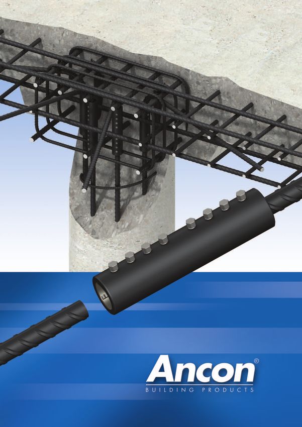
Reinforcing Bar Couplers
    Simplify the design and construction of concrete
    Lapped joints are not always an               the concrete could significantly
    appropriate means of connecting               affect the performance of the
    reinforcing bars. The use of laps             joint. The strength of a
    can be time consuming in terms                mechanical splice is independent
    of design and installation and                of the concrete in which it is
    can lead to greater congestion                located and will retain its
    within the concrete because of                strength despite loss of cover as
    the increased amount of rebar                 a result of impact damage or
    used.                                         seismic event.
    Ancon couplers can simplify the               The Ancon range of reinforcing
    design and construction of                    bar couplers is the most
    reinforced concrete and reduce                comprehensive available and
    the amount of reinforcement                   includes tapered threaded,
    required.                                     parallel threaded, mechanically
    Lapped joints are dependent                   bolted and grouted couplers.
    upon the concrete for load                    Stainless steel couplers complete
    transfer. For this reason any                 the range.
    degradation in the integrity of

    Contents
    MBT ET Series                          4-5
    MBT Transition Series                    6
    MBT Continuity Series                    7
    MBT Headed Anchors                       8
    Other Ancon Products                     9

    Eurocode 2 compliant    Simplify design and    ISO 9001, ISO 14001,   Available through major   Dedicated sales
                               construction            OHSAS 18001          rebar stockists and        support
                                                                           approved distributors

2   Tel: +44 (0) 114 275 5224   www.ancon.co.uk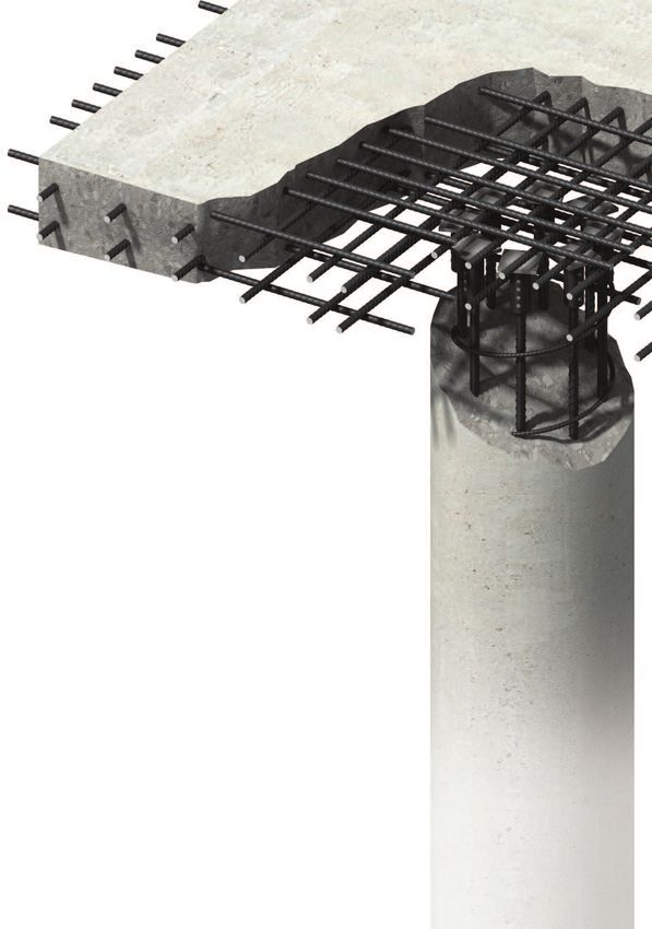
3
Reinforcing Bar Couplers
MBT
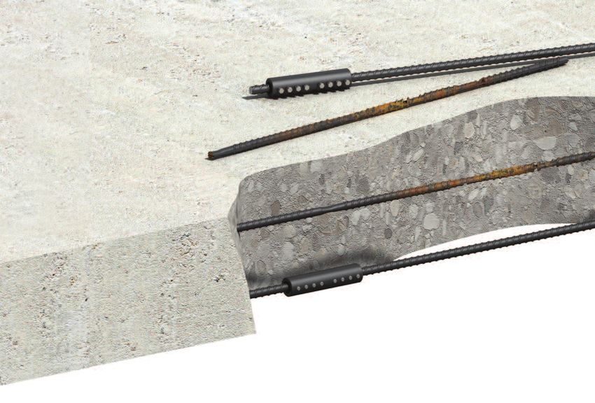
The MBT range of couplers provides a cost-effective method of joining reinforcing bars, particularly when
the fixed bar is already in place and there is insufficient space for a hydraulic swaging press.
MBT Couplers are easy to install and achieve Testing & Approvals In addition the coupler has been tested to
failure loads higher than 115% of the Full destructive tests are show compliance with the following
characteristic yield strength of grade 500 carried out on selected international design codes:- BS EN 1992-1-1:
reinforcing bar. Neither bar end preparation to couplers from our CERTIFICATE No 98/R102 2004 (Eurocode 2), BS5400, BS8110, ACI 318
form threads, nor bar rotation are required. stocks. MBT couplers are and DIN 1045 German code.
MBT couplers can also be used to join designed and manufactured Note: Not all coupler types and sizes are relevant to the
national approvals shown. For details of coupler types and
imperial, plain round or deformed reinforcing in accordance with sizes relevant to each national approval please refer to the
BS EN ISO 9001. relevant approval document, which is available on request.
bars.
The most common Lockshear bolt
The bar ends are supported within the coupler
sizes of ET series
by two serrated saddles, and as the lockshear Reduced diameter
couplers are approved by the BBA and are shear plane
bolts are tightened, the conical ends embed
covered by the Roads and Bridges Agrément
themselves into the bar. As this happens the
Certificate No. 98/R102. Sizes ET10, 12, 14,
serrated saddles bite into both the bar and the
16, 20, 25 and 28 have been tested and
shell of the coupler. The lockshear bolts of
approved by the DIBt and are covered by
couplers up to and including the ET20 can be
Approval No Z-1.5-10. Further national Serrated saddle
tightened using a ratchet wrench. For larger
approvals include BMVIT Approval No. -
couplers a nut runner is recommended.
327.120/0018-II/ST2/2006, and SITAC
In all cases heavy duty sockets should be used. Approval No.0541-95 which
When the pre-determined tightening torque for covers the ET Series and Section showing the embedment of the
the bolts is reached, the heads shear off leaving lockshear bolts and saddles into the
Continuity C Series. The full
bar and the shell of the coupler
the top of the installed bolt slightly proud of the range of MBT Couplers is
coupler. This provides an instant visual check of certified by GOST for the
correct installation. Russian Federation.
Note: Impact tools must not be used to tighten
lockshear bolts.
l
MBT ET Series
The MBT ET series of couplers is used to
connect reinforcing bars of the same size. d
Bar Diameter 10 12 14 16 18 20 22 25 26 28 30 32 34 36 40
External Diameter d 33.4 33.4 42.2 42.2 48.3 48.3 48.3 54.0 66.7 66.7 71.0 71.0 75.0 85.0 81.0
Total Length l 100 140 160 160 204 204 248 258 312 312 312 312 420 484 484
Socket Size A/F (ins) 1
/2 1
/2 1
/2 1
/2 1
/2 1
/2 1
/2 5
/8 5
/8 5
/8 5
/8 5
/8 3
/4 3
/4 3
/4
No. of Bolts 4 6 6 6 8 8 10 8 10 10 10 10 12 14 14
Approx Weight (kg) 0.52 0.72 1.25 1.25 2.0 1.96 2.38 3.00 5.91 5.80 6.68 6.50 8.85 15.30 11.30
Part No. ET10 ET12 ET14 ET16 ET18 ET20 ET22 ET25 ET26 ET28 ET30 ET32 ET34 ET36 ET40
Note: MBT ET50 couplers can be manufactured. For details contact Ancon Building Products.
4 Tel: +44 (0) 114 275 5224 www.ancon.co.uk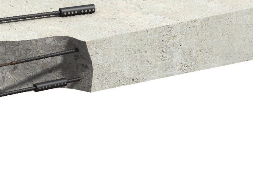
Installation
MBT ET Series

 1                                                   2                                                   3

Place the coupler over the end of the bar to half   Place the other bar end into the coupler until it   On one half of the coupler, starting from the
the coupler length +/- 6mm and finger tighten       pushes up against the first bar and finger          centre and working outwards, partly tighten the
the lockshear bolts onto the bar. Check the         tighten the remaining lockshear bolts. Check        lockshear bolts using either a ratchet wrench or
alignment and make any necessary adjustments.       alignment and make any adjustments.                 a nut runner as appropriate. Do not use impact
                                                                                                        tools. Repeat again, this time fully tightening the
                                                                                                        lockshear bolts until the bolt heads shear off.
                                                                                                        Repeat the above for the other half of the
                                                                                                        coupler.

Repair and Remedial Work                            Electric Wrench
For applications involving replacement of           Ancon Electric Wrenches are available for purchase or hire. The smooth continuous action of the
corroded or damaged bars, the replacement           wrench prevents the early shearing of the lockshear bolts and damage to threads. The wrench is
bar is cut approximately 5mm shorter to             supplied with specially hardened heavy duty sockets. For details please contact Ancon.
allow clearance for insertion between the
sound ends of the original bars. MBT
couplers are pushed fully over both ends of
the replacement bar and temporarily held in
position.
The replacement bar is then correctly
positioned and the couplers moved to a
previously marked position on the existing
bars indicating half the length of the coupler.
The lockshear bolts are tightened to
complete the installation.

                                                                                                                                                              5
Reinforcing Bar Couplers

    MBT Transition Series
    The MBT Transition series of couplers provides an effective solution for connecting bars of different diameters.
    Transition couplers have all of the benefits of
    the ET series and are designed to achieve
    failure loads higher than 115% of the
    characteristic yield strength of the smaller                                   d                                          l
    grade 500 reinforcing bar.
    They can be installed without any preparation
    to the bar ends and without any need to rotate                                                                                                                     d2
    bars.
    The coupler can be rotated to allow access to
    the bolts for tightening with either a ratchet                                                        a
    wrench or a nut runner. In all cases heavy duty
                                                                                                                                             b
    sockets should be used. Transition couplers
    are non-standard and are made to order.
    Note: Impact tools should not be used to tighten
    lockshear bolts.

    MBT Transition Series Dimensions
    Bar Diameter                       16/12      16/14      20/12      20/16      25/16      25/20      28/20      28/22         28/25    32/20       32/25      32/28      40/32
    External Diameter         d        42.2        42.2       48.3       48.3       54.0       54.0       66.7       66.7        66.7       71.0        71.0       71.0       81.0
    External Diameter         d2       26.4        42.2       33.4       48.3       42.2       54.0       48.3       41.7        54.0       48.3        54.0       66.7       71.0
    Total Length               l       160         160        150        160        155        180        204        253         258         177        231        286        335
    Individual Lengths       a:b      80:80       80:80      80:70      80:80      75:80      90:90     102:102    129:124     129:129     75:102     102:129    130:156    178:157
    Socket Size A/F (ins)    a:b      1
                                       /2:1/2     1
                                                   /2:1/2    1
                                                              /2:1/2    1
                                                                         /2:1/2    5
                                                                                    /8:1/2    5
                                                                                               /8:1/2    5
                                                                                                          /8:1/2    5
                                                                                                                     /8:1/2     5
                                                                                                                                 /8:5/8     5
                                                                                                                                             /8:1/2    5
                                                                                                                                                        /8:5/8    5
                                                                                                                                                                   /8:5/8    3
                                                                                                                                                                              /4:5/8
    No. of Bolts             a:b        3:3         3:3        3:3        3:3        2:3        3:3        3:4        4:5         4:4         2:4        3:4        4:5        5:5
    Approx Weight (kg)                 1.30        1.25       1.13       1.56       1.51       2.23       2.94       3.61        3.98       2.55        3.70       5.71       7.47
    Part No.                         ET16/12     ET16/14    ET20/12    ET20/16    ET25/16    ET25/20    ET28/20    ET28/22     ET28/25    ET32/20     ET32/25    ET32/28    ET40/32

    Installation
    MBT Transition Series

     1                                                           2                                                             3

    Place the coupler over the end of the bar to the            Place the other bar end into the coupler until it             On one half of the coupler, starting from the
    appropriate depth +/- 6mm and finger tighten                pushes up against the first bar and finger                    centre and working outwards, partly tighten
    the lockshear bolts onto the bar. Check the                 tighten the remaining lockshear bolts. Check                  the lockshear bolts using either a ratchet
    alignment and make any necessary adjustments.               alignment and make any adjustments.                           wrench or a nut runner as appropriate. Do not
                                                                                                                              use impact tools. Repeat again, this time fully
                                                                                                                              tightening the lockshear bolts until the bolt
                                                                                                                              heads shear off.
                                                                                                                              Repeat the above for the other half of the
                                                                                                                              coupler.

6   Tel: +44 (0) 114 275 5224           www.ancon.co.uk
MBT Continuity C Series
 The MBT Continuity coupler allows reinforcement to be extended at construction joints without the need to
 drill or otherwise substantially deface the formwork.
 The female part of the C series coupler is
 fixed to the formwork with the aid of a nail                d
                                                                                                                 l
 plate.                                                                                             c
 After removal of the formwork, the nail plate
 protects the internally threaded end of the
 coupler. It is advisable to loosen the nail plate to
 break the bond with the concrete whilst it is still
 'green'. When the nail plate is removed, the                                              a
 male section can be screwed into the existing
 section of the coupler.
 The 12mm and 16mm couplers have
 additional locknuts which are used to secure            Bar Diameter                                    12              16        20          25           32          40

 the connection. The two sections of sizes               External Diameter                     d         33.4         42.2        48.3        54.0        71.0        81.0
                                                         Maximum Length                        l         250          280         349         414         490         675
 20mm to 40mm couplers are locked together
                                                         Female Component Length               a         100          115         147         177         214         300
 by an expanding cone in the male section.               Threaded Section                      c          30           35          38          43          53          53
                                                         Socket Size A/F (ins)                            1
                                                                                                           /2          1
                                                                                                                        /2         1
                                                                                                                                    /2         5
                                                                                                                                                /8         5
                                                                                                                                                            /8         3
                                                                                                                                                                        /4
                                                         No. of Bolts                                      6            6           8           8          10          14
                                                         Nail Plate Diameter x Thickness                75 x 5       75 x 5      75 x 5      100 x 5     100 x 5     127 x 5
                                                         Approx Weight (kg)                              1.40         2.20        3.70        5.15        11.5        18.8
                                                         Part No.                                        C12          C16         C20         C25         C32         C40
Installation

 1                                                       2                                                           3

Fix the nail plate to the formwork and fully            Starting from the nail plate end and working             Remove the formwork and unscrew the nail
screw the female component onto the plate.              outwards, partly tighten the lockshear bolts             plate. The male component can now be fully
Insert the bar into the coupler, ensuring that          using either a ratchet wrench or a nut runner            screwed into the fixed female component.
it does not encroach into the threaded section.         as appropriate. Do not use impact tools.                 The male component can be rotated up to a
Finger tighten the lockshear bolts. Check               Repeat again, this time fully tightening the             full turn to allow the bolts to be located in an
alignment and make any adjustments.                     lockshear bolts until the bolt heads shear off.          accessible position for tightening.
                                                        Cast in concrete.

 4                                                       5

                                                                                                                     Note: When the coupler is fully assembled the visible
                                                                                                                     threaded stud between the two locknuts must not
                                                                                                                     exceed 20mm.

                                                                                                                     Note: The Continuity Coupler male component will be
Run the locknut along the threaded male stud            Place the continuation bar into the male                     delivered with the threaded stud already in place and the
to abut the female component. Fully tighten             component and finger tighten the bolts. Check                locknuts located on the threaded stud. If the female
                                                                                                                     component is to be left insitu for an extended period, the
the locknut against the female section using            alignment and make any adjustments. Starting                 threads must be greased to prevent corrosion.
a wrench.                                               from the centre and working outwards, partly
                                                        tighten the lockshear bolts using either a ratchet
                                                        wrench or a nut runner as appropriate. Do not
                                                        use impact tools. Repeat again, this time fully
                                                        tightening the lockshear bolts until the bolt
                                                        heads shear off. Fully tighten the locknut.                                                                               7
Reinforcing Bar Couplers

                                                              MBT Headed Anchors
                                                              MBT Headed Anchors are designed to provide dead end embedment
                                                              for bars in concrete. This helps to reduce congestion and simplify the
                                                              placement of rebars by removing the need for hooked ends.
                                                              The anchor comprises half an MBT coupler with a plate welded to one end which carries the full
                                                              tension load of the bar when it is bearing against the concrete. The MBT Headed Anchor also has
                                                              the added advantage of requiring no special bar end preparation.

                                                                                                                 lo

                                                                                                                                      t

                                                                                      d

                                                                                                                                           p

                                                                                                                 l

    Bar Diameter                      10       12       14       16      18      20       22     25      26      28      30     32        34    36      40
    External Diameter         d      33.4   33.4   42.2   42.2   48.3   48.3   48.3   54.0   66.7   66.7   71.0   71.0   75.0   85.0   81.0
    Coupler Length             l      55     75     82     82     104    104    126    129    156    156    156    156    215    247    247
    Total Length              lo      65     85     92     92     114    114    136    139    168    168    171    171    230    262    262
    Plate Thickness            t      10     10     10     10      10     10     10     10     12     12     15     15     15     15     15
    Plate w x h               p       70     70     70     80      90     90     90    100    110    110    130    130    130    150    150
    Socket Size A/F (ins)             1
                                       /2    1
                                              /2    1
                                                     /2    1
                                                            /2     1
                                                                    /2    1
                                                                           /2    1
                                                                                  /2    5
                                                                                         /8    5
                                                                                                /8    5
                                                                                                       /8    5
                                                                                                              /8    5
                                                                                                                     /8    3
                                                                                                                            /4    3
                                                                                                                                   /4    3
                                                                                                                                          /4
    No of Bolts                        2      3      3      3      4      4      5      4      5      5      5      5      6      7      7
    Approx Weight (kg)               0.64   0.74   1.01   1.07   1.58   1.58   1.72   2.29   3.81   4.14   5.08   4.72   5.17   9.13   8.30
    Part No.                        ETHA10 ETHA12 ETHA14 ETHA16 ETHA18 ETHA20 ETHA22 ETHA25 ETHA26 ETHA28 ETHA30 ETHA32 ETHA34 ETHA36 ETHA40

    Note: Minimum compressive strength of concrete 25N/mm2.

8   Tel: +44 (0) 114 275 5224         www.ancon.co.uk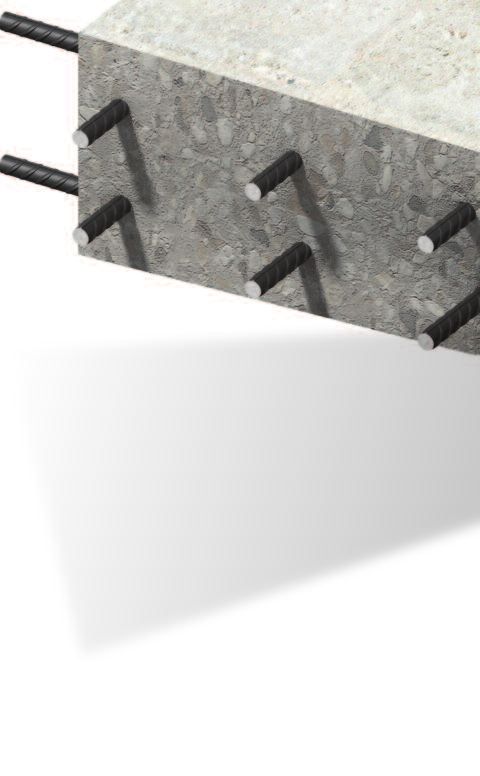
Other Ancon Products
Reinforcement Continuity Systems
Reinforcement Continuity Systems are an increasingly popular means of maintaining continuity of
reinforcement at construction joints in concrete. The Ancon Eazistrip re-bend system is approved
by UK CARES and consists of pre-bent bars housed within a galvanised steel casing. Once
installed, the bars are straightened ready for lapping with slab reinforcement. Ancon KSN Anchors
and Ancon Starter Bars are cast into a concrete wall and accept threaded continuation bars. They
easily accommodate long EC2 lap lengths and eliminate the need for on-site bar straightening.
KSN Anchors minimise rebar congestion in the wall.
Shear Load Connectors
Ancon DSD and ESD Shear Load Connectors are used to transfer shear across expansion and
contraction joints in concrete. They are more effective at transferring load and allowing movement
to take place than standard dowels. The range features rectangular box section sleeves to allow
lateral movement in addition to longitudinal movement. A range of Lockable Dowels is available for
temporary movement joints in post-tensioned concrete.
Channel and Bolt Fixings
Ancon offers a wide range of channels and bolts in order to fix stainless steel masonry support,
restraints and windposts to structural frames. Cast-in channels and expansion bolts are used for
fixing to the edges of concrete floors and beams.
Punching Shear Reinforcement
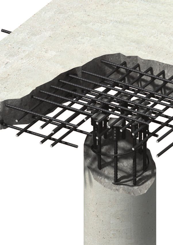
Ancon Shearfix is used within a slab to provide additional reinforcement from punching shear
around columns. The system is approved by UK CARES and consists of double-headed steel
studs welded to flat rails. Shearfix is designed to suit the load conditions and slab depth at each
column using free calculation software from Ancon.
Insulated Balcony Connections
Ancon’s thermally insulated connectors minimise heat loss at balcony locations while maintaining
structural integrity. They provide a thermal break and, as a critical structural component, transfer
moment, shear, tension and compression forces. Standard solutions are available for concrete-to-
concrete, steel-to-concrete and steel-to-steel interfaces.
9
Masonry Support Systems
Lintels
Masonry Reinforcement
Windposts and Parapet Posts
Wall Ties and Restraint Fixings
Channel and Bolt Fixings
Tension and Compression Systems
Insulated Balcony Connectors
Shear Load Connectors
Punching Shear Reinforcement
Reinforcing Bar Couplers
Reinforcement Continuity Systems
Stainless Steel Fabrications
Flooring and Formed Sections
Refractory Fixings

Ancon Building Products              Ancon Building Products                     Ancon (Schweiz) AG                                   Ancon GmbH
President Way, President Park        98 Kurrajong Avenue                         Gewerbezone Widalmi 10                               Bartholomäusstrasse 26
Sheffield S4 7UR                     Mount Druitt                                3216 Ried bei Kerzers                                90489 Nuremberg
United Kingdom                       Sydney NSW 2770                             Switzerland                                          Germany
Tel: +44 (0) 114 275 5224            Australia                                   Tel: +41 (0) 31 750 3030                             Tel: +49 (0) 911 955 1234 0
Fax: +44 (0) 114 276 8543            Tel: +61 (0) 2 8808 3100                    Fax: +41 (0) 31 750 3033                             Fax: +49 (0) 911 955 1234 9
Email: info@ancon.co.uk              Fax: +61 (0) 2 9675 3390                    Email: info@ancon.ch                                 Email: info@anconbp.de
Visit: www.ancon.co.uk               Email: info@ancon.com.au                    Visit: www.ancon.ch                                  Visit: www.anconbp.de
Follow on Twitter: @AnconUK          Visit: www.ancon.com.au

Ancon (Middle East) FZE              Ancon Building Products                     Ancon Building Products
PO Box 17225                         2/19 Nuttall Drive                          GesmbH
Jebel Ali                            Hillsborough                                Puchgasse 1
Dubai                                Christchurch 8022                           A-1220 Vienna
United Arab Emirates                 New Zealand                                 Austria
Tel: +971 (0) 4 883 4346             Tel: +64 (0) 3 376 5205                     Tel: +43 (0) 1 259 58 62-0
Fax: +971 (0) 4 883 4347             Fax: +64 (0) 3 376 5206                     Fax: +43 (0) 1 259 58 62-40
Email: info@ancon.ae                 Email: info@ancon.co.nz                     Email: info@ancon.at
Visit: www.ancon.ae                  Visit: www.ancon.co.nz                      Visit: www.ancon.at

                                                The construction applications and details provided in this literature are indicative only. In every case, project working
These products are available from:
                                                details should be entrusted to appropriately qualified and experienced persons.

                                                Whilst every care has been exercised in the preparation of this document to ensure that any advice, recommendations or
                                                information is accurate, no liability or responsibility of any kind is accepted in respect of Ancon Building Products.

                                                With a policy of continuous product development Ancon Building Products reserves the right to modify product design
                                                and specification without due notice.

© Ancon Building Products 2014
You can also read