ME 4670 / 5670 Engineering Biomechanics of Human Motion - Laboratory Exercises Spring 2021 Dr. Robert L. Williams II Mechanical/Biomedical Engineering
←
→
Page content transcription
If your browser does not render page correctly, please read the page content below
ME 4670 / 5670

            Engineering Biomechanics of Human Motion

                                Laboratory Exercises
                                    Spring 2021

                         Dr. Robert L. Williams II
                    Mechanical/Biomedical Engineering
                             Ohio University

                            williar4@ohio.edu
                   ohio.edu/mechanical-faculty/williams

These laboratory exercises are adapted from the laboratory manual associated with:

      N. Hamilton, W. Weimar, and K. Luttgens, 2008, Kinesiology: Scientific Basis of Human Motion,
  th
11 edition, McGraw-Hill, Boston, MA.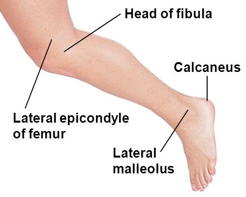
2
                                                   Table of Contents

LABORATORY REPORT FORMAT ................................................................................................... 3

SIGNIFICANT FIGURES ....................................................................................................................... 4

LAB 1. VECTORS ................................................................................................................................... 5

LAB 2. KINETICS ................................................................................................................................. 12

LAB 3. RANGE OF MOTION ............................................................................................................. 17

LAB 4. ANALYSIS OF PUSH-PULL MOTIONS.............................................................................. 21

LAB 5. CENTER OF GRAVITY (CG)................................................................................................ 27

LAB 6. WORK, POWER, FRICTION, ELASTICITY ..................................................................... 33

LAB 7. TORQUE ................................................................................................................................... 42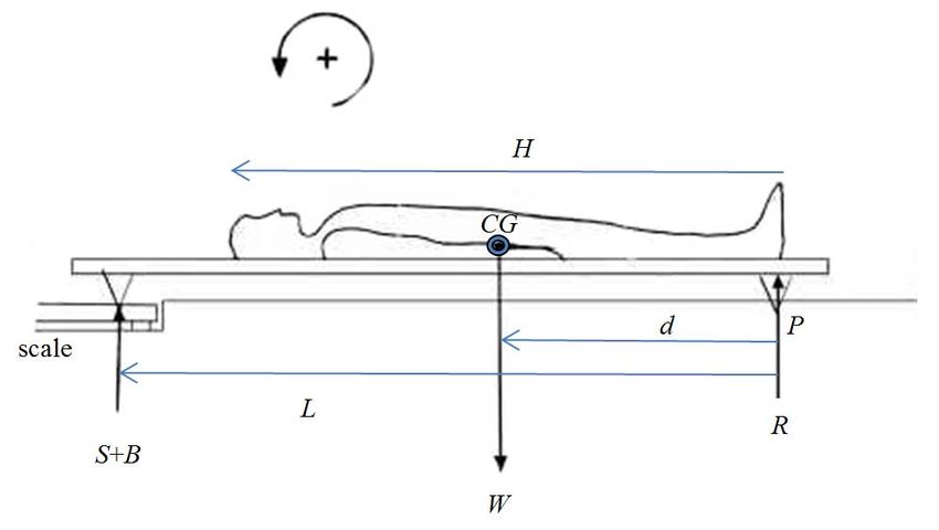
3
Laboratory Report Format
        This section presents the required report format for the ME 4670 / 5670 laboratories all semester.
From previous experience I have found that most student teams can do the laboratories and get reasonable
results easily enough. In order to obtain the best grade possible on each laboratory, you should focus on
clear, complete, technical report writing with extra effort. Include plenty of clear sketches, graphics,
and digital photos and good discussion on all points. In addition, include overall Discussion and
Conclusion sections for all lab reports.

        Feel free to use graphics from any valid source, but you MUST acknowledge the source in your
report (where it appears in your report AND in the report bibliography). Complete website references are
valid.

       One report is to be submitted for each lab for each lab team (2-3 students).

       MEMO (serves as the Abstract) – first page, no cover sheet necessary

       1. Objectives

       2. Background

       3. Results

       4. Discussion

       5. Conclusion

       Bibliography

       Appendices (as necessary)
4
Significant Figures
Significant figures (abbreviated sig figs or s.f.) are important in any branch of science and
engineering involving numerical calculations. It is my observation that with the advent and mainstream
use of digital calculators and computers, many students, faculty, and engineers have lost sight of the
important concept of significant figures. Please pay attention to significant figures in all Biomechanics of
Human Motion laboratories this semester – indeed, in all of your engineering work in the future.
The amount of significant figures in any number is the amount of digits with meaning. This is
related to the precision of a number or measurement, which is the degree of closeness a number is reported
to. In calculations involving multiple numbers, the amount of significant figures in the result must be
equal to that of the least significant number that enters the calculations.
One cannot report more digits in a measurement than is warranted by the measuring device. For
instance, in a protractor marked to the nearest 1 degree, I was taught that you can report results to the
nearest ½ degree, but the result is significant only to the nearest degree.
Significant Figures Rules
all non-zero digits are significant
15 has two sig figs and 5.4321 has five sig figs
leading zeros or trailing zeros are not significant unless otherwise stated
0.15 has two sig figs, 0.00015 also has two sig figs, and 200 has one sig fig
exceptions:
200. has three sig figs, 200 has two sig figs, and 200 has three sig figs
trailing zeros after the decimal point are significant
0.000150 has three sig figs and 0.00015000 has five sig figs
intermediate zeros are significant
101 has three sig figs and 202.408 has six sig figs
scientific notation has the same rules
1.5x10⁻⁴ has two sig figs and 1.5000x10⁻⁴ has five sig figs5
Lab 1. Vectors
Objectives
Define key biomechanical measurement terms and state how each relates to the structure of
biomechanics study.
Convert the units of measurement employed in the study of biomechanics from the U.S. system to
the metric system, and vice versa.
Demonstrate the use of the graphic method for the combination and resolution of two-dimensional
vectors.
Demonstrate the use of the trigonometric method for the combination and resolution of two-
dimensional vectors.
Identify the scalar and vector quantities represented in individual motor skills and describe the
vector quantities using vector diagrams.
Background
The units of measurement employed in the study of biomechanics are expressed in terms of space,
time, and mass. Presently in the United States, there are two systems of measurement having units for
these quantities, the U.S. system and the metric system. Although the metric system is currently used in
research and literature, a comparison of equivalent values is helpful.
Quantities that are used in the description of motion may be classified as either scalar or vector in nature.
Scalar quantities are single quantities. They possess only size or amount. This size or amount is referred
to as magnitude and completely describes the scalar quantity. The units of measure described in the
previous section are primarily scalar quantities, described only by magnitude. Examples of scalar
quantities would be such things as a speed of 8 kilometers per hour, a temperature of 70 degrees, an area
of 2 square kilometers, a mass of 10 kilograms, or a height of 2 meters.
There are also double quantities that cannot be described by magnitude alone. These double quantities are
called vector quantities. A vector quantity is described by both magnitude and direction. Examples of
vector quantities would be a velocity of 8 kilometers per hour in a northwest direction, 10 Newtons of
force applied at a 30-degree angle, a displacement of 100 meters from the starting point. The importance
of clearly designating vector quantities can be seen if the direction component of the double quantity is
altered. For instance, if two people on opposite sides of a door push with equal magnitudes (amounts) of
force, the door will not move. If, on the other hand, they both push on the same side of the door, thus
changing the direction of one of the forces, the result will be very different. The nature of the movement
of the door depends upon both the amount and direction of the force. Force, therefore, is a vector quantity.
If the individual who ran 8 kilometers runs 8 more kilometers, the total distance run will be 16 kilometers.
However, if the runner goes 8 kilometers in one direction, reverses, and runs back to the starting point,
the change in position or displacement is zero. The runner is zero kilometers from the starting point.
Displacement, then, is also a vector quantity possessing both magnitude and direction. Numerous
quantities in biomechanics are vector quantities. In addition to force, displacement, and velocity already
mentioned, some other examples are momentum, acceleration, friction, work, and power. Vector
quantities exist whenever direction and amount are inherent characteristics of the quantities.6
A vector is represented by an arrow whose length is proportional to the magnitude of the vector. The
direction in which the arrow points indicates the direction of the vector quantity. Vector quantities are
equal if magnitude and direction are the same for each vector. Although all the vectors below are of the
same length (magnitude) only two are equal vector quantities.
Vectors may be combined by addition, subtraction, or multiplication. They are added by joining the head
of one with the tail of the next while accounting for magnitude and direction. The combination results in
a new vector called the resultant. The resultant vector is represented by the distance between the last head
and the first tail.
The subtraction of vectors is done by changing the sign of one vector (multiply by -1) and then adding as
before. The multiplication of a vector by a number changes its magnitude only, not its direction.
As just explained, the combination of two or more vectors results in a new vector. Conversely, any vector
may be broken down or resolved into two component vectors acting at right angles to each other. Should
one wish to know how much of a velocity was in a horizontal direction and how much in a vertical
direction, for instance, the resultant vector (R) must be resolved into horizontal and vertical components.
The vector addition of these components once again would result in the resultant vector R.
Any vector may be resolved into horizontal and vertical components if the trigonometric relationships of
a right triangle are employed. Let us use the example of the jumper whose velocity at takeoff was 9.6
meter/sec in the direction of 18 degrees with the horizontal. To find the horizontal velocity (Vx) and
vertical velocity (Vy) at takeoff a right triangle is constructed. With the takeoff velocity (R) as the
hypotenuse of the triangle, the vertical and horizontal components of velocity become the vertical and
horizontal sides of the triangle. To obtain the values of Vx and Vy the sine and cosine functions are used.
The horizontal velocity of the jump Vx turns out to be 9.1 m/s.
The combination of vectors is also possible with the use of right triangle trigonometric relationships. If
two vectors are applied at right angles to each other the solution should appear reasonably obvious since
it is the reverse of the example just explained. If a baseball is thrown with a vertical velocity of 15
meter/sec and a horizontal velocity of 26 meter/sec the velocity of the throw and the angle of release may
be determined by using the Pythagorean Theorem to find the magnitude of the resultant vector and using
the tangent function (tan-1) to find the appropriate angle. The resultant velocity--that is, the velocity of
the throw--is 30 meter/sec and the angle of projection is 30 degrees.
If more than two vectors are involved or if they are not at right angles to each other as shown in previous
examples, the resultant may be obtained by determining the x and y components for each individual vector
and then summing these individual components to obtain the x and y components of the resultant. Once
the x and y components are known, the magnitude and direction of R may be obtained.
As we have seen before, a knowledge of the horizontal (x) and vertical (y) components makes it possible
to determine the resultant vector. A triangle is formed and the unknown parts are found.
Sig Figs
For this report only, assume you have sufficient precision in each number to report all results to
the nearest tenth decimal place.7
Lab 1 Report – Vectors
Name(s) Date
1. Define the following key terms in your own words.
kinematics
statics
dynamics
scalar
vector
2. Express the following terms in SI units.
a. a force of 25 pounds
b. a mass of 5 slugs
c. a distance of 11 inches
d. a velocity of 20 feet per second
e. a volume of 3 quarts8
3. Determine the distance and angle (polar notation) between each set of points. Draw a vector diagram
to scale for each case.
a. (2,3); (5,7) b. (1,2); (3,3)
c. (1.5,3.0); (6,6) d. (0,0); (6.2, 3.6)
4. Find the x and y components for each of the following vectors. Draw a vector diagram to approximate
scale for each case. Unless otherwise specified (see #9 orienteering later) in this course, always measure
angles with the right hand from the positive horizontal.
a. 45 m at 25° b. 85 m/sec at 135°
c. 118 m/sec2 at 210° d. 225 N at 310°9
5. A basketball official runs 20 meters along the sideline in one direction, reverses, and runs 8 meters.
Draw the vector diagram.
What is the distance run? What is the displacement?
6. The force of a muscle is 650 N, pulling on a bone at an angle of 15 degrees. Draw the diagram (assume
the bone is horizontal). What are the horizontal and vertical components of this force?
7. At the moment of release, a baseball has a horizontal velocity component of 25 meters per second and
a vertical velocity component of 14 meters per second. Draw the diagram.
At what angle was it released?
What was its initial velocity in the direction of the throw in meters/sec?
8. A child is being pulled in a sled by a person holding a rope that has an angle of 20 degrees with the
horizontal. The total force being used to move the sled at a constant forward speed is 110 N. Draw the
diagram.
How much of the force is horizontal?
How much of the force is vertical?10
9. An orienteer runs the following course: 1000 meters at 45°; 1500 meters at 120°; 500 meters at 190°.
Assume all angles are measured in an absolute manner (not relative to the previous leg), left-handed with
respect to the positive vertical direction (true north is the standard reference in orienteering). Note
compass readings are left-handed: N 0°, E 90°, S 180°, and W 270°.
a. Draw the course to scale accurately on a separate piece of paper.
b. Determine the resultant displacement graphically from a.
c. Determine the resultant displacement trigonometrically.
d. Express the orienteer's position at the end of the course in terms of rectangular coordinates and
also in terms of polar coordinates.
e. Explain any differences between your graphic and trigonometric results.
10. A football lineman charges an opponent with a force of 175 pounds in the direction of 310 degrees.
The opponent charges back with a force of 185 pounds in the direction of 90 degrees. Draw the vector
diagram. What is the resultant force and in what direction will it act? This problem should be interpreted
in the top view, with forces in the horizontal plane.11 11. Refer to the drawing of the femur and adductor longus muscle. Draw a straight line to represent the main long mechanical axis of the femur and another to represent the muscle's effective line of pull. a. Using a protractor, determine the angle of pull of the muscle (angle formed by muscle's line of pull and mechanical axis of bone – this is called the angle of pennation). Clearly show your measurement in the diagram above. b. Assuming a total muscle force of 900 N, calculate the XY force components. Clearly show your XY reference axes in the diagram above. 12. Muscle A has a force of 450 N and is pulling on a bone at an angle of 15 degrees. Muscle B has a force of 600 N and is pulling on the same bone at the same spot but at an angle of 30 degrees. Muscle C has a force of 325 N and is pulling at the same spot with an angle of pull of 10 degrees. All angles should be measured with the right hand from the absolute horizontal. Draw the vector diagram. What is the composite effect of these muscles in terms of amount of force and direction? (i.e. find the resultant force using vector addition, and report it in polar coordinates.)
12
Lab 2. Kinetics
Objectives
State Newton's laws as they apply to both linear and rotary motion.
Explain the cause and effect relationship between the forces responsible for linear motion and the
objects experiencing the motion.
Explain the cause and effect relationship between the forces responsible for rotary motion and the
objects experiencing the motion.
Explain the analogous kinetic relationships that exist between linear and rotary motion.
Background
There is a relationship between linear and angular kinematics based on the length of the radius of
a lever. The greater the distance from the axis to a point the greater will be the displacement of the point
and the derivatives of displacement.
Newton’s three laws govern motion in this universe. These three laws are:
1. Law of Inertia – a body at rest will remain at rest and a body in motion will remain in motion until
acted upon by an outside force.
2. Law of Acceleration – acceleration of a body is directly proportional to force and indirectly
proportional to mass (F = ma).
3. Law of Reaction – for every action there is an equal and opposite reaction.
The quantity of motion that an object possesses is referred to as momentum. Momentum is a product of
mass and velocity (mv). Since a change in velocity is an acceleration and since acceleration requires the
application of a force over some period of time, it requires a force over a period of time to change
momentum. This is called impulse (Ft). Momentum within a system, once established, remains constant
until an impulse is applied.
When two objects collide the total momentum of the system will be the sum of the momentums imparted
by each object.
Equipment
Two balls of unequal mass
Push stick
Smoothly rotating chair or platform
Block of wood
Plastic bat, batting tee, indoor ball
Weighted bags
Note: if you are lacking some of these items, DO NOT go shopping. Instead substitute what you have
handy and clearly report what you used and what the results were. If adequate substitutes are not freely
available, you and your partner can instead use thought experiments with virtual equipment to satisfy the
requirements in those sections – at no penalty.13
Lab 2 Report – Kinetics
Name(s) Date
Experiment 1
Equipment: two balls of unequal mass (e.g. golf ball and table tennis ball), push stick
1. Place the two balls against the stick. Applying even force along the length of the stick, push the two
balls approximately 10 cm. Stop the stick suddenly and observe the action of the balls.
Draw the motion diagram including all important parameters.
What type(s) of motion did you observe?
In what way did the balls exhibit the motion(s) observed?
Which ball travels farther?
Give a mechanical reason for this result.
2. Repeat the experiment, using the same force, but push for approximately 20 cm.
In which of the two trials did the balls travel farther?
Give a mechanical reason for this difference.14
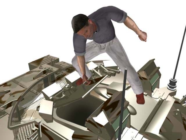
Experiment 2
Equipment: rotating platform or chair
1. Have a subject sit on the rotating platform or chair in such a way that no part of the body is in contact
with the floor. Start the platform or chair spinning. As the platform or chair spins, have the subject
suddenly abduct the arms.
Draw the motion diagram including all important parameters.
What happens to the rotation when the arms are abducted?
Give a mechanical reason for your results.
2. Repeat the experiment. Immediately following the abduction of the arms have the subject quickly
adduct again, bringing the arms in close to the body.
What happens to the rotation in this case?
Give a mechanical explanation for your results.
3. Have the subject attempt to start the platform rotating, with no contact on any external surface by either
the arms/hands or the legs/feet.
Is the subject successful in this attempt?
Give a mechanical explanation for this success or failure.15
Experiment 3
Equipment: wooden block, notebook
1. Put the block on top of the notebook that is flat on the floor. Quickly jerk the notebook towards you.
Draw the motion diagram including all important parameters.
What happens to the block?
Give a mechanical reason for this result.
2. Now pull the notebook towards you slowly.
What happens to the block?
Give a mechanical reason for this result.
3. Now pull the notebook towards you smoothly but rapidly. Stop the notebook abruptly.
What happens to the block?
Give a mechanical reason for this result.16
Experiment 4
Equipment: plastic bat, batting tee, indoor ball
With the bat, hit the ball from the tee and mark its landing point. Next, toss the ball up to yourself, hit it,
and mark the landing point. Finally, hit a ball that is pitched to you and mark the landing point. Use a
consistent swing speed throughout the experiment.
Draw the motion diagram including all important parameters.
Under which condition did the ball travel the furthest? The second and third furthest?
Give a mechanical reason for these results.
Experiment 5
Equipment: weighted bags
Perform a standing long jump under each of the following conditions. Mark the distance jumped for each
condition. Draw the motion diagrams including all important parameters.
a. Using no arm motion.
b. Using a swinging motion of the arms.
c. Same as b while holding a weight in each hand.
d. Same as c plus swing the weights forward as you jump. At the peak of the jump throw the
weights down and backward. This one may require some practice.
Rank the four jump conditions from longest to shortest.
Give at least 2 mechanical reasons for these results.17
Lab 3. Range Of Motion
Objectives
Name the factors that contribute to joint range of motion and stability, and explain the relationship
that exists between range of motion and stability.
Assess a joint's range of motion, evaluate the range, and describe desirable procedures for changing
it when indicated.
Background
The mobility of joints is dependent upon several factors. The bony structure of the joint is the
primary determinant of the type of motion allowed. The range of motion refers to the actual degree to
which joint motion is able to occur.
Active range of motion is that arc of excursion or the degree of motion possible through voluntary
muscle action. Passive range of motion is that range of motion possible without injury or discomfort
through the action of an outside force.
For human joint range of motion averages please see Dr. Bob’s ME 4670 / 5670 NotesBook,
Appendix B.
If a goniometer is not available, you can make your own or simply use a protractor in all cases.
Procedures
1. Locate the following bony landmarks and mark lightly with a pen or chalk.
a. greater tubercle of humerus e. greater trochanter (femur)
b. head of radius f. lateral condyle of femur
c. styloid process of ulna g. lateral malleolus
d. head of fifth metacarpal h. proximal end, fifth metatarsal
2. Have the subject assume the base starting position for each joint measurement as follows:
a. Elbow flexion – From the anatomical position, shoulder abduction to 90° with the elbow fully
extended and the hand in supination.
b. Wrist extension – same as above.
c. Hip flexion – Lie on a firm, flat surface in a supine position. With the knees bent, fully flex both
hips.
d. Hip hyperextension – Lie prone on a firm, flat surface. Keeping both sides of the crest of the ilium
in contact with the surface and the knee fully extended, hyperextend the right hip.
e. Knee flexion – Assume a supine lying position with the knee fully extended and the hip at
approximately 45° - 50°. Use caution when performing passive knee hyperextension in this
position.
f. Ankle – In a sitting position with the knee and ankle at 90°. The foot should be well clear of the
floor. The goniometer axis must be below the malleolus.18 3. Place the goniometer on the subject so that the fixed arm of the goniometer is along the mechanical axis of the proximal, or fixed, segment of the active joint. The axis or 0° mark of the goniometer should be at the joint axis for the joint to be measured. Make sure that the protractor part of the goniometer is toward the direction of motion. Place the moveable arm of the goniometer along the mechanical axis of the segment moved after the final range of motion position has been reached. Do not try to keep the goniometer on the moving segment during the motion. All measurements should be done on the same side of the body. 4. Record your results for maximum active and passive range of motion in both flexion and extension (or hyperextension, or dorsiflexion/plantar flexion) of the Lab Report. Answer all discussion questions. 5. Graph your results. A bar chart will work well, your team must arrange the plots for maximum graphical communication. 6. Include photos of your measurement setup. Also include annotated digital photos and/or sketches for all of your joint limits results.
19
Lab 3 Report – Range of Motion

Name(s)                                                                   Date

                                      Ranges of Motion in Degrees

         Joint                         Flexion                            Hyperextension
                            Active                  Passive          Active            Passive
 Elbow
 Hip

         Joint                         Flexion                                Extension
                            Active                  Passive          Active               Passive
 Wrist
 Knee

         Joint                       Dorsiflexion                         Plantar Flexion
                            Active                  Passive          Active             Passive
 Ankle

1. Where did your active range of motion measurements fall outside the limits of those presented as
average? (See Dr. Bob’s ME 4670 / 5670 NotesBook, Appendix B, for active motions only.) Be specific
as to joint name and amount of difference found.

                                Ranges of Motion Differences (+ or -)

                            Joint                Flexion         Hyperextension
                    Elbow
                    Hip

                            Joint                Flexion            Extension
                    Wrist
                    Knee

                            Joint             Dorsiflexion       Plantar Flexion
                    Ankle

2. Speculate on specific reasons for you as an individual that might account for any for the differences
you found in each joint.
20 3. Compare your active range of motion to your passive range of motion. In general, which of the two was greater? How would you explain this difference? 4. What anatomical or structural factors either enhance or limit range of motion in each joint tested?
21
Lab 4. Analysis of Push-Pull Motions
Objectives
Name and discuss anatomical and mechanical factors and principles that apply to representative
push or pull activities.
Analyze a subject’s performance of a different push-pull skill under each of these force application
conditions: momentary contact, projection, and continuous application (defined later).
Background
In pushing and pulling patterns of motion, the basic joint actions are flexion and extension in one
or more of the extremities. The joint actions in the upper extremities are characterized by flexion and
extension in the elbow while the opposite movement is occurring in the shoulder. In the lower extremities,
extension occurs simultaneously in the hip, knee, and ankle. This simultaneous and opposite joint action
is a primary characteristic of push-pull patterns. All joint motions occur at the same time or very near the
same time.
The simultaneous nature of the joint motions in push and pull patterns produces a rectilinear path
of motion at the distal end point of the segments involved, as opposed to a curvilinear path. Such a
rectilinear path means that all forces produced by segmental motion are applied directly to the object and
that this force is applied in the direction of motion. Keeping this in mind makes it apparent that the
primarily simultaneous push-pull patterns are of greatest value when it is important to apply a large force
(overcome a large resistance) or to apply a force with maximum accuracy. All the forces involved are
applied directly in line with the object being moved. There are no large-magnitude tangential forces.
A push, pull, or lift may be applied either directly or indirectly to an object. In the latter instance,
the push or pull pattern is used for the purpose of developing potential energy in an elastic device such as
a bow or slingshot. When the elastic structure is released, it imparts force to the movable object, causing
the arrow or shot to be projected into the air.
Procedures
Working with your partner, select a different simple push-pull skill for each aspect (Momentary
Contact, Projection, and Continuous Application) of this lab.
From the Push-Pull Movement Principles listed on the next page, derive a qualitative checklist
for each skill. The checklist should include all of the critical elements necessary to insure that a skill is
performed with optimum safety, effectiveness, and efficiency.
For each critical element included as part of the checklist, provide a rationale for inclusion.
Have one student act as a subject and perform the selected skill. Apply the checklist that has been
developed to the performance. Based on the qualitative checklist evaluation, make suggestions for
improvement of the skill performance, based on sound mechanical principles.22
Push-Pull Movement Principles (Hamilton et al., 2008)
Principles relating to the magnitude of force:
1. The object will move only if the force is of sufficient magnitude to overcome the object’s inertia.
2. Force exerted by the body will be transferred to an external object in proportion to the effectiveness
of the counterforce of feet (or other body parts) against the ground (or other supporting surface).
3. Optimum summation of internal force is needed if maximum force is to applied to move an object.
4. For maximum accuracy, the smallest possible number of segments should be used through the
smallest possible motion range.
5. For a change in momentum to occur, force must be applied over time (impulse); maximum forces
require maximum time ranges of application.
Principles relating to the direction of force:
1. The direction in which the object moves is determined by the direction of the force applied to it
(Newton’s Second Law).
2. If an object is free to move only along a predetermined path (e.g. a sliding door), any component
of force not in the direction of this path is wasted and may increase friction.
3. When optimum force production is the purpose of the push or pull pattern, those segments involved
should be aligned with the direction of intended force production.
Principles relating to the point at which the force is applied:
1. Force applied in line with an object’s center of gravity will result in linear motion of the object,
provided it is freely movable.
2. If the force applied to a freely movable object is not in line with the object’s center of gravity,
rotary motion will result.
3. If the free motion of an object is interfered with by friction or by the presence of an obstacle, rotary
motion may result, even though the force is applied in line with the object’s center of gravity.23
Momentary Contact, Projection, and Continuous Application Forces Definitions
rehab.ym.edu.tw/document/motion/Throw.pdf
Momentary Contact
Force imparted to an object through temporally contact with that object by a moving part of the
body segment or by implement held or attached on the body segment. The object may be either stationary
or moving.
Examples
on moving object – baseball striking, soccer heading or kicking, volleyball set, or tennis shots
on stationary object – tennis serve, golf driving
Projection
Force imparted to an object through the end of a chain of body segments in order to develop kinetic
energy, followed by a high-velocity motion of that object. The object may be held in one hand or hands.
Examples
for distance – shotput, javelin, or volleyball serve
for accuracy – baseball pitching or dart throw
Continuous Application
Force imparted to an object with the force continuously applying to that object.
Examples
against large resistance – pushing a desk or lifting weight
maintain a position while waiting for a release – archery24 Lab 4 Report – Analysis of Push-Pull Motions Name(s) Date Momentary Contact Selected skill: Performer Checklist: Sketches: 1. 2. 3. 4. Attach additional numbers as necessary. Include sketches for your push-pull skill (one for each step in the checklist). Are there any noticeable deviations from the performance described by the checklist? If so, describe each one: What is the probable cause of each of these deviations? What specific suggestions would you make for the improvement of performance?
25
Projection

Selected skill:                                                           Performer

Checklist:                                          Sketches:

1.

2.

3.

4.

Attach additional numbers as necessary. Include sketches for your push-pull skill (one for each step in
the checklist).

Are there any noticeable deviations from the performance described by the checklist? If so, describe
each one:

What is the probable cause of each of these deviations?

What specific suggestions would you make for the improvement of performance?
26
Continuous Application

Selected skill:                                                           Performer

Checklist:

1.

2.

3.

4.

Attach additional numbers as necessary. Include sketches for your push-pull skill (one for each step in
the checklist).

Are there any noticeable deviations from the performance described by the checklist? If so, describe
each one:

What is the probable cause of each of these deviations?

What specific suggestions would you make for the improvement of performance?
27
Lab 5. Center of Gravity (CG)
Objectives
Define the term center of gravity, and explain the basis for its location in the human body.
Locate the center of gravity of an individual using the reaction board and the segmental method.
Background
The center of gravity of a body is sometimes described as its balance point or that point about
which a body would balance without a tendency to rotate. For this reason, the center of gravity is often
identified as the point where all of the weight of the body or object is concentrated. More accurately, it is
the point where the weight of the body may be said to act.
The ability to locate the center of gravity of a body is based on the knowledge of what it takes for a system
to be balanced, or in equilibrium. There are two conditions that must be met:
All the linear forces acting on the body must be balanced.
All the rotary forces (torques) must be balanced.
Another way of expressing these necessary conditions for equilibrium is to say that the sum of all the
forces acting on the body must equal zero. If there is a downward-directed linear force, there must be an
equal upward force so that the vector sum of these forces equals zero. If there is a negative clockwise
torque it must be canceled out by a positive counterclockwise torque of equal magnitude.
The location of the center of gravity of any object remains fixed as long as the body does not change
shape. In rigid bodies of homogeneous mass, the center of gravity is at the geometric center. Where the
density of a rigid body varies, the center of gravity is not at the geometric center but is shifted toward the
more weighted section. If an object's shape or position changes, the location of the center of gravity will
also change. This happens in the human body. It is a segmented structure, capable of numerous positions,
and the location of its center of gravity changes accordingly. This is an important consideration in the
execution of sports skills.
According to:
hypertextbook.com/facts/2006/centerofmass.shtml
“The average ratio of center of mass to height in females is approximately 0.543 and the average ratio of
center of mass to height in males is approximately 0.560.” (measured from the ground).
That is, the center of gravity of average adult females is 54.3% of their height, measured up from the
ground. The center of gravity of average adult males is 56.0% of their height, measured up from the
ground. Thus, the center of gravity is usually located somewhat lower in women than in men.
Your team must use both the reaction board and the segmental methods, as stated above.
However, if you cannot get ahold of all the required equipment, DO NOT buy anything – just do a virtual
experiment, filling in appropriate numbers after using the numerical segmental method.28
Reaction Board Method
It is a fairly simple matter to find an estimate of the center of gravity of a motionless body using
the reaction board method. Making use of the principle of moments, this procedure relies on the statics
principle that the sum of the moments acting on a body in equilibrium is zero. The center of gravity of the
body is found according to the method below.
Equipment
Scales
Block (same height as the platform of the scales)
A board about 40 cm wide and L = 200 cm long with knife edge supports (see figure)
Procedure
1. Find the subject's total weight, W.
2. Put one knife-edge of board on scale platform and the other edge on box platform. Use a level to make
sure the board is horizontal. Note the reading on the scales (without the subject). This is the partial weight
of the board, B.
3. Have the subject lie supine on the board with the heels against the footrest at the end of the board away
from the scales. The position the subject assumes should be as similar to the standing position as possible.
Record the reading on the scales. This is the partial weight of the subject and board, S.
4. For static equilibrium to exist about the point P (the foot knife-edge support), the counterclockwise (+)
torques must equal the clockwise (–) torques. Again, W is the total weight of the subject, B the partial
weight of the board, S the partial weight of the subject and board, L the length of the board, and d the
distance from P to the human body CG, then:
M Z 0
Wd ( S B ) L
(S B) L
d
W
The distance between the subject's feet and center of gravity is d. This is comparable to the distance
between the ground and the center of gravity when the subject is standing, but must be viewed as an
estimate because of shifts in body organs and tissues when lying down.
5. The percentage height of the center of gravity with respect to the subject's total height is found by
dividing the value of d by the subject's total height H and multiplying by 100%.
d
% CG 100%
H29
Here is the associated figure. Draw your own in your report.
Reaction Board Method Figure30
Segmental Method
With information on the proportionate mass of body segments and the location of the center of
gravity of each segment (see Appendix D), the center of gravity of the whole body in any plane may be
determined by making use of the principle of torques. The sum of the torques of the individual segments
about arbitrarily placed x and y axes will produce the location of the center of gravity of the whole body
with respect to the x and y axes. This is because the total body weight acting at the center of mass is the
resultant of the combined segment weights acting at their CGs and the resultant moment of the total body
weight about the x, y axes is the sum of the individual segment torques about the same axes.
Equipment
Line drawing on graph paper
Procedure
1. Mark the locations of the extremities of the individual segments according to the link boundaries shown
in the human CG figure of Appendix D of the ME 4670 / 5670 NotesBook.
2. The extremity limits are joined to form a stick figure consisting of 14 segments, some in series and
some in parallel.
3. The CG location for each segment length is found using the data provided in the figure of Appendix D
of the ME 4670 / 5670 NotesBook, where centers of gravity are located as a percentage of the distance
between segment end points. The amount of the percentage distance from one segment end point is
multiplied by the length of the segment. The resulting product is the distance from the selected end point
to the center of gravity of the segment. The distance is measured from the end point, and the center of
gravity is marked by the standard symbol. Caution – the segment CGs given in Appendix D are measured
from the proximal end of each segment.
4. Draw x and y axes on the paper.
5. The x, y coordinates for each of the 14 segment CGs are determined and recorded on the diagram of the
figure at the respective CGs.
6. Record the x, y coordinate values on the worksheet.
7. Multiply the x coordinate and the y coordinate each by the proportion of body weight listed in the second
column. Record this result in the columns labeled x product and y product.
8. The algebraic sum of the x products represents the x coordinate of the total body's CG, and the algebraic
sum of the y products is the y coordinate. These values are located and marked on the tracing.31
Lab 5 Report – Center of Gravity
Name(s) Date
Reaction Board Method
Data to be used:
Subject’s body weight (W) Length of the board (L)
Weight of the pivoted board sensed by the scale (B) Subject’s height (H)
Weight of the subject while lying on the board (S)
1. Find height of the center of gravity measured from the feet.
(S B)L
d
W
2. Find the location of the center of gravity as a percentage of the total height.
d
% CG 100%
H
3. How does the location of your center of gravity compare with that presented as average for your gender
(higher, lower, same)?1
4. Provide an anatomical explanation for the location of your center of gravity as compared to the average.
1
The average ratio of center of mass to height in females is approximately 0.543 and the average ratio of center of mass to height in males
is approximately 0.560 (from the ground). http://hypertextbook.com/facts/2006/centerofmass.shtml32
Segmental Method
Worksheet (use an Excel spreadsheet)
Body Segment Proportion of x value x product y value y product
Body Weight
Trunk 0.4684
Head & Neck 0.0826
R. Thigh 0.1050
R. Lower Leg 0.0475
R. Foot 0.0143
L. Thigh 0.1050
L. Lower Leg 0.0475
L. Foot 0.0143
R. Upper Arm 0.0325
R. Forearm 0.0187
R. Hand 0.0065
L. Upper Arm 0.0325
L. Forearm 0.0187
L. Hand 0.0065
x-y Resultants
(product total)33
Lab 6. Work, Power, Friction, Elasticity
Objectives
Explain the work-energy relationship as it applies to a body experiencing linear motion.
Define and use properly the terms work, power, kinetic energy, and potential energy.
Background
Work is defined as the product of force and the distance through which that force moves an object,
in the direction in which the force is applied (W = F d).
Power is the rate at which work is done (P = W / t).
Energy is defined as the ability to do work. Potential energy (PE) is energy based on position.
Kinetic energy (KE) is energy based on motion. Energy within a system is conserved. That is, the total
energy is the sum of PE and KE.
Friction is the tangential component of force which acts between two surfaces to resist sliding or
rolling. The coefficient of friction is determined by the nature of the two surfaces.
Elasticity is the ability of an object to resist deformation and to resume its’ original shape once it
has been deformed. Elasticity is described in terms of an object coefficient of restitution.
Equipment
assortment of surfaces
assortment of balls
board marked at 10 cm and 20 cm
meter stick
steel ball bearing or golf ball
spring scale (see Friction section)
stopwatch
tape measure
weight34
Lab 6 Report – Work, Power, Friction, Elasticity
Name(s) Date
In all experiments, be careful to make sure that your units are consistent (you may not mix pounds with
meters). Also in all experiments, make a drawing of the motion diagram including all important
parameters.
Work & Power
Equipment: stopwatch, meter stick
You will need to record the following before you start:
Subject body weight (in Newtons) N
Vertical height of stairs m
(hint - measure a single step and multiply)
1. Time the subject as they walk up the stairs. Time:
Draw the motion diagram including all important parameters.
Calculate the work done and calculate the power produced.
W=Fd W= P=W/t P=
Briefly explain what these two quantities indicate in this experiment.35
2. Repeat the experiment with the subject running up the stairs. Time:
Draw the motion diagram including all important parameters.
Calculate the work done: W =
How does this compare to the first trial?
Give a mechanical explanation for this comparison.
Calculate the power produced. P=
How does this compare to the first trial?
Give a mechanical explanation for this comparison.36
Energy
Equipment: marked board, steel ball bearing or golf ball
3. Place the board on the floor with the 20 cm end propped up on some stable object ( such as a book or a
block). Start the bearing or ball at the 10 cm mark on the board. Release the bearing or ball and let it roll.
Record the time it takes to travel the first meter after it leaves the board. Record the total distance the
bearing travels. Record the height of the board at the 10 cm mark.
Draw the motion diagram including all important parameters.
Mass of shot (kg) Height of 10 cm mark (m)
Time for 1st meter (sec)
Calculate the potential energy possessed by the bearing before release.
PE = mgh PE =
Calculate the kinetic energy possessed by the bearing in motion.
KE = ½ m v2 KE =
Are the potential energy and the kinetic energy approximately the same?
Give a mechanical explanation for this result.
Calculate the frictional force that was applied to the bearing to bring it back to rest.
Total distance (d, m) F = KE / d F=37
4. Repeat the experiment, but start the bearing from the 20 cm mark on the board. Record the time taken
to cover the first meter, the total distance covered, and the height of the 20 cm mark.
Height of 20 cm mark (m)
Time for 1st meter (sec)
Calculate the potential energy possessed before release.
PE = mgh PE =
Calculate the kinetic energy possessed in motion.
KE = ½ m v2 KE =
Are the potential energy and the kinetic energy approximately the same?
Give a mechanical explanation for this result.
Calculate the frictional force that was applied to the bearing to bring it back to rest.
Total distance (d, m) F = KE / d F=38
5. Do the following comparisons between the two trials.
Which of the two trials possessed the greatest PE?
Why was this so?
Which of the two trials produced the greatest KE?
Give a mechanical explanation for this result.
In which trial was the greatest force generated?
Give a mechanical explanation for this result.
Repeat Experiment 2 with other balls. Record your results on a separate sheet of paper.39
Friction
If you do not have access to a spring scale, do not buy one. Instead, turn the experiment around (research
on the Internet to find common coefficients of friction for a shoe on various surfaces) and perform the
friction experiment (Steps 6, 7, and 8) using calculations instead of measurements.
Equipment: weighted shoe, spring scale, a variety of surfaces (floor, a board, carpet, AstroTurf, artificial
track, etc.)
6. Place the weight in the shoe. Attach the spring scale to the shoe and weigh it (W). Place the shoe on a
wooden board. Pull horizontally on the spring scale just until the shoe starts to move. Make sure you do
not exert any upward force on the shoe, as this will reduce friction. Read the pulling force (P) from the
scale and record it below.
Draw the motion diagram including all important parameters.
W= P=
Calculate the coefficient of friction ( µ ).
µ = P/W µ=
7. Repeat this experiment on as many different surfaces as you can find.
Surface P µ
Which of these surfaces produced the greatest coefficient of friction?
Give a mechanical explanation for this result.40
8. Place the weighted shoe on the board. Now tilt the board until the shoe just barely begins to slide.
Measure the angle between the board and the floor. The tangent of this angle will be the coefficient of
friction (derive this result).
µ = tan µ=
Does this agree with the µ you found in trial #1 of this experiment?
Give a mechanical explanation for this result.41
Elasticity
Equipment: an assortment of balls
9. Fix a tape measure to a vertical surface. Drop each ball in turn from a height of 2 meters onto the floor.
Measure the height. Coefficient of elasticity:
height of rebound
e
height of drop
Ball Rebound height e
Draw the motion diagram including all important parameters.
Which ball has the greatest observed elasticity?
Give a mechanical explanation for this result.
10. Repeat the experiment using as many different landing surfaces as you have time for. (Record your
results on an additional piece of paper.)
What were the effects of the different surfaces on the elastic response of the balls?42
Lab 7. Torque
Objectives
Solve simple lever and torque problems involving the human body and the implements it uses.
Evaluate the true muscular effort force required to support a given external resistance.
Enhance understanding of the nature of torque and its effects on the body.
Background
The rotating effect of an eccentric force is called torque or moment. The torque about any point
equals the product of the force magnitude and the perpendicular distance from the line of the force to the
axis of rotation. The perpendicular distance between the force vector and the axis is called the moment
arm. Herein, the rotating effect will be referred to as torque and the perpendicular distance as moment
arm.
Since torque is the product of force and the moment arm length, it may be modified by changing
either the force or the moment arm. Torque may be increased by increasing the magnitude of the force or
by increasing the length of the moment arm. Decreasing either of these factors will produce a decrease in
torque. In supporting a weight at the end of a fully extended arm for instance, if the magnitude of the
weight were decreased, the torque would also decrease. Conversely, increasing the weight would increase
the torque.
Torque acts at the joint. Force acts on a lever. Torque is a function of an applied force times the
perpendicular distance from the axis at which that force is applied (T = d x F). Forces can be either effort
or resistance forces. For a system or a lever to be in equilibrium these two types of forces must create
equal and opposite torques:
E x EA = R x RA
Biceps-Like Moment Diagram
E – effort force EA – effort moment arm
R – resistance force RA – resistance moment arm43
Equipment
meter stick
load (e.g. book bag with books)
stopwatch
goniometer (or protractor)
Procedures
1. On your subject locate the Lateral Femoral Epicondyle and the Lateral Malleolus. Measure the distance
between the two landmarks and record this on your lab report as the lower-leg segment length (RA2).
2. Using the converted weight of the subject in N (see lab report), determine the weight of the lower leg.
Use the data provided to find the location of the center of gravity of the lower leg segment, as measured
from the knee.
3. Show the leg weight (R1) and the distance to the center of gravity (RA1) on the free body diagrams
(FBDs) of the right and left legs that you must sketch.
4. Calculate the location (EA) of the attachment of the quadriceps muscle group to the tibia using the
percentage given on the lab report. Show this on the FBDs and note the muscle angles of pull on the FBDs.
5. Have the subject sit on a table. Fix equal loads to each ankle. Have the subject then extend the left leg
horizontally as fully as possible (with the thigh fully supported). The right knee is extended to an angle of
150 , determined by goniometer (that is, drop the lower leg down 30 from horizontal knee extension).
Hold these positions as long as possible. Record the holding time for each leg.
6. Record the magnitudes of the external loads (R2) on the lab report form and on the two FBDs. Show
the segment length (RA2) on the two FBDs.
7. Using standard torque calculation, calculate the actual muscle force required by the quadriceps muscle
group of each leg in order to support the external load.44
Lab 7 Report – Torque
Name(s) Date
Record the following information and do the required calculations to produce the relevant data.
Body weight = lbs. x 4.45 = N
Segment weight (R1) = body weight N x 0.045 = N
Segment length (RA2) = meters
Center of gravity location (RA1):
Segment length meters x 0.433 = meters
Muscle attachment (EA):
Segment length meters x 0.12 = meters
External load (R2) = lbs. x 4.45 = N
Draw the associated figure.45
Draw the free body diagrams (FBDs) for both legs with this data.
Data to be used:
R1 (segment weight) N RA1 (center of gravity) m
R2 (external load) N RA2 (segment length) m
EA (effort arm, distance to muscle attachment) m
RA is the resistance arm for the loads
Calculate the torque produced by the resistance.
(R1 x RA1) + (R2 x RA2) = TR
TR = Nm
Calculate the rotary component of the muscle force required to produce an equal and opposite torque.
TR = Ey x EA therefore Ey = TR/EA
Ey = N
Calculate the total muscle force for the rotated leg.
E = Ey / sin( 30 )
E= N Time held: sec46
Draw the associated figure.
Calculate the rotary components of the resistance forces.
R1y = N R2y = N
Calculate the torque produced by the resistance.
(R1y x RA1) + (R2y x RA2) = TR
TR = Nm
Which of the two resistance torques is greater (straight leg or bent leg)?
What is the reason for this?47
Calculate the rotary component of the muscle force required for the straight leg.
E = TR/EA
E= N Time held sec
In which leg was the greatest muscle force required?
Using the concept of torque and the principle of levers in equilibrium, explain why this is so.
Which leg had the longest holding time?
Explain this result. Base your answer on the answer to the previous question.You can also read