Minimizing Warpage for Macro-Size Fused Deposition Modeling Parts
←
→
Page content transcription
If your browser does not render page correctly, please read the page content below
Computers, Materials & Continua                                                             Tech Science Press
DOI:10.32604/cmc.2021.016064
Article

                          Minimizing Warpage for Macro-Size Fused
                                 Deposition Modeling Parts
     Thanh Thuong Huynh1, Tien V. T. Nguyen2,3 , Quoc Manh Nguyen4 and Trieu Khoa Nguyen2, *

             1
                Department of Mechanical Engineering, Can Tho University, Campus II, Can Tho, Vietnam
    2
      Faculty of Mechanical Technology, Industrial University of Ho Chi Minh City, Ho Chi Minh, 70000, Vietnam
            3
              Mechanical Engineering Department, National Kaohsiung University of Science and Technology,
                                               Kaohsiung, 80778, Taiwan
  4
    Faculty of Mechanical Engineering, Hung Yen University of Technology and Education, Hung Yen, 16000, Vietnam
                   *
                     Corresponding Author: Trieu Khoa Nguyen. Email: nguyenkhoatrieu@iuh.edu.vn
                                Received: 21 December 2020; Accepted: 22 February 2021

                 Abstract: In this study, we investigated warpage and corner lifting mini-
                 mization for three-dimensional printed parts generated by macro-size fused
                 deposition modeling (FDM). First, the reasons for warpage were theoreti-
                 cally elucidated. This approach revealed that the thermal deformation and
                 differential volumetric shrinkage of the extruded molten plastic resulted in
                 warpage of FDM parts. In addition, low adhesion between the deposited
                 model and the heated or non-heated printing bed may intensify warpage
                 further. As a next step, initial small-size and medium-size models were used
                 to identify parameters to manage and minimize warpage in a way that would
                 reduce material consumption and running time. Finally, a macro-size model
                 was built to experimentally investigate and verify the technical solutions
                 to minimize the warpage of FDM parts. In conclusion, an improved part
                 with reduced warpage was efficiently produced after detailed consideration
                 of thermal effects and adhesion force. Potential exists to widen the appli-
                 cation scope of FDM technology in manufacturing for processes like ther-
                 moforming that involve mold core fabrication with heating. This technology,
                 which has applications not only in mechanical engineering but also in related
                 engineering fields, is convenient and could readily be applied to practical
                 manufacturing industries.

                 Keywords: Fused deposition modeling; corner lifting; volumetric shrinkage;
                 thermal deformation; acrylonitrile butadiene styrene filament

1 Introduction
     Fused deposition modeling (FDM), which is a filament-based technology, has become a
simple and useful tool for three-dimensional (3D) printing [1]. In FDM, the temperature of
a thermoplastic filament is increased to its melting point and subsequently forced through a
cylindrical spout following the layer-by-layer cross-section of the model. The technique has several
advantages including low maintenance costs, absence of toxic materials, and low-temperature

                     This work is licensed under a Creative Commons Attribution 4.0 International License,
                     which permits unrestricted use, distribution, and reproduction in any medium, provided
                     the original work is properly cited.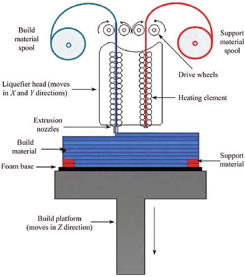
2914                                                                          CMC, 2021, vol.68, no.3

operation. However, some of the most commonly observed disadvantages include bad surface
roughness due to seam lines between layers and warpage or corner lifting phenomena. Many
researchers have focused on numerical and experimental investigations of warpage. Numerical
simulation of warpage was utilized to comprehend the interaction between process parameters and
material properties [2]. The authors of this study concluded that an optimizing process must be
performed to lessen internal stresses for the minimization of warpage. Wang et al. [3] concluded
that the main reason for warpage was thermal stress due to temperature gradients. They built a
mathematical function of the warpage to quantitatively analyze the relevant parameters, including
the material linear shrinkage rate α, the stacking section length L, the chamber temperature Te ,
and the number n of deposition layers, as a scientific tool for controlling and fine-tuning the
warpage. In addition to studies of thermal stresses, a coupled thermal and mechanical analysis
was used to mimic the FDM process [4] where the agglomeration of residual stresses at the
bottom area of the printing part was the main cause of warpage. The authors suggested that scan
speed and layer thickness were the most important factors that affected warpage. Sood et al. [5]
performed experimental studies on the impact of essential process parameters that included raster
width, air gap, raster angle, part orientation, and layer thickness. They examined the influence of
these parameters on dimensional accuracy. The authors proposed that the printing process must
be based on optimal settings to enhance dimensional accuracy. In other investigations [6], the
authors also examined printing parameters that enhanced the stress accumulation along the paths
of deposition causing more warpage of parts. The functional relation between building parameters
and strength (flexural, impact, and tensile) for the FDM process has also been constructed using
the response surface method for the prediction of warpage. In addition, researchers [7] quantified
experimentally the influences of geometric forms and process parameters on the distortion of
printing parts having thick-and thin-wall characteristics. The authors determined that the internal
thermal stress may combine with the mass distribution to have an impact on dimensional accuracy,
which was an extremely important evaluation index. Other studies [8] showed that sufficiently
high thermal differences might cause warpage of the final printing parts. The authors claimed
that the thermal history [9–11] of the printed path was of significant importance because it was
the greatest determining parameter in the bonding quality between adjacent paths of material.
Furthermore, Chau et al. [12] concentrated on process parameter optimization [13–17]. Parameters
such as extrusion velocity, line width compensation, filling speed, and layer thickness were chosen
as control parameters (input variables), while dimensional error, warp distortion, and printing
time were chosen as outcome responses (evaluation indicators). The optimal results [18,19] were
validated by confirmation experiments utilizing the response surface method in conjunction with
the fuzzy inference system. A study by Peng et al. [20] proposed that a slightly negative air gap
setting and thermal gradients resulted in the distortion of the physical dimensions of the printing
parts. A negative air gap or negative fiber-to-fiber gap [21,22] denotes that the distance between the
centers of two adjacent deposited molten filaments is smaller than the setting value of the height
of the layer. While many investigations of the surface quality in FDM technology were performed,
a way to systematically overcome warpage was needed. Almost all previous investigations that
dealt with the warpage problem were about processing parameters [23]. General investigation for
all relevant processes including pre-processing and processing parameters is needed. An experi-
mental investigation for elucidating the reasons for warpage and minimizing this phenomenon was
therefore performed in the present study.
    In the remainder of this paper, Section 2 introduces the materials and methods used in our
study. Section 3 describes the main results and discussion for the experimental process. Finally,
the conclusions are presented in Section 4.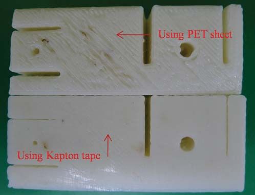
CMC, 2021, vol.68, no.3                                                                        2915

2 Materials and Methods
2.1 Fused Deposition Modeling (FDM)
    The FDM technology was developed in the late 1980s and was commercialized in the early
1990s [24,25]. It offers several advantages, including nontoxic materials, unlimited geometric com-
plexity, use with many types of materials, short operation cycle, easy changes of material, low
processing temperature, small-size equipment, and low maintenance expenses [20,26]. In a normal
FDM process, the heated nozzle plastic melts and extrudes a plastic by following the layer-by-
layer cross-section of the part, which results in various layers of combined little strands as shown
in Fig. 1 [27]. Consequently, the final printed model is formed by a matrix of little strands
with the exception of the peripheral shell. Therefore, the constructed part can be observed as a
porous model.
    The FDM process is a layered manufacturing technology. It builds the desired 3D models
directly from the computer-aided design (CAD) files or stereo lithography (STL) file. Therefore,
the main disadvantages of this technology are due to seam lines between every two nearby small
strands. These seam lines inherently induce a low surface quality or may even cause a loosening
of layer-layer adhesion. Another important drawback is due to the thermal conductivity for
polymeric materials utilized in the FDM technology. Furthermore, the polymer FDM parts’ ability
to withstand low heat prevents the widespread utilization of the FDM process.

                Figure 1: Illustration of a commonly used FDM technology [28]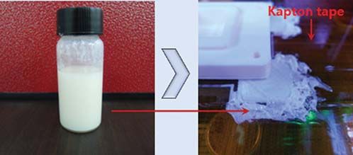
2916 CMC, 2021, vol.68, no.3
2.2 Warpage in FDM
Thermal deformation and differential volumetric shrinkage of the extruded polymer melt
mostly induce warpage in FDM models [29,30] just like the common warpage defects observed
in injection molding technology. The inner core of the printed model usually has a greater
temperature because of quicker cooling in the outermost shell or the peripheral layers as shown
in Fig. 2. This imbalance in cooling induces inconsistent shrinkage, and therefore deformations
lead to warpage or corner lifting. A loosening of adhesion between the built model and building
bed may enhance the corner lifting or warpage more.
Figure 2: Corner-lifting or warpage phenomenon in FDM: (a) Top view of the FDM part, (b) side
view of the FDM part, and (c) side view of the deformed model
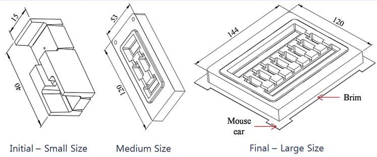
2.3 Fabrication of Specimens
As a first step, 3D models were designed using a commercial CAD software program (Solid-
Works). An initial small-size model was used to identify initial parameters. Medium-size model
was used to reduce material consumption as well as running time. Minimizing corner lifting in
the final large-size model was the target goal of this investigation as shown in Fig. 3. Next,
the designed modeling 2D CAD sketches were converted to folders for differently formatted
files (including STL) that are commonly utilized for 3D additive print. The STL files were then
transformed into printable or buildable 3D files by splitting the designed parts into finite layers
using the 3D printing software. The software also determined the appropriate deposition paths
for the printing. The models were then printed out using ABS filaments on a commercial 3D
printing machine (Cubicon Single) [30]. It should be noted that with an exact range of 0.025–
0.6 mm, the utilized 3D printing machine resulted in somewhat poor printing quality. The models
with the low surface-quality were purposely chosen to illustrate the performances of the proposed
post-processing approach.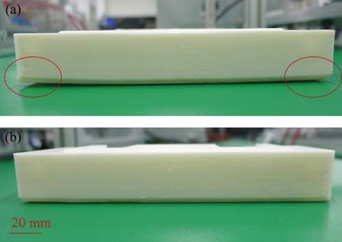
CMC, 2021, vol.68, no.3                                                                        2917

                   Figure 3: Three types of FDM specimens used in this study

3 Results and Discussions
    In the pre-feasibility printings, corner lifting could be easily observed, even with the initial
small-size samples. This defect prevented the 3D printing machine from being efficiently used as
shown in Fig. 4.

                     Figure 4: Corner-lifting/warpage phenomenon in FDM

    Hence, several pre-processing steps were carried out to efficiently enhance the stickiness
between the printed model and the printing or building bed as follows: (i) The initial Z-height of
the FDM equipment was carefully calibrated to print an initial layer sufficient for the extruded
strand to cling onto the building bed with ease; (ii) the current building bed was covered by a
polyimide tape with high heat resistance; (iii) the polyimide tape was painted using an ABS glue
to form a thin ABS film to increase the stickiness of the extruded ABS strand onto the building
bed as shown in Fig. 5; (iv) additional things were added to the model, for example, mouse ears
and/or brims for better adhesion of the outermost layers and the corners to the printing bed;
and (v) supplement drops of ABS glue were added between the mouse ears and/or brims to
increase stickiness.
    The relative parameters were also thoroughly handled during printing to miniaturize the
thermal deformation and differential volumetric shrinkage as follows: (vi) The lowest possible
printing or building temperature was set, which is needed for a reliable fabrication, but also
generates good interlayer stickiness (250 ◦ C for the current ABS wire); (vii) the part was printed
at a low velocity (60 mm/s for the current case) for the built model to cool down evenly; (vii) the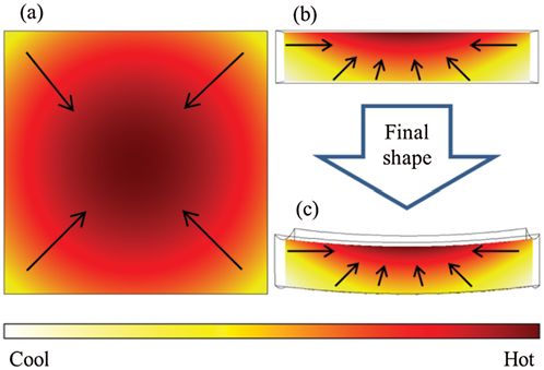
2918                                                                         CMC, 2021, vol.68, no.3

building velocity was adjusted to the sole floor layer (first layer), which was slower in comparison
to the cardinal printing velocity for increasing the stickiness of 30 mm × s−1 for the current cases;
and (ix) the printing bed temperature was controlled at 110 ◦ C, a little above the glass transition
temperature of ABS polymeric material (about 105 ◦ C), to let the fabricated model cool down
more evenly.

                    Figure 5: The use of ABS glue on additional mouse ears

    These nine important results served as the guidelines for us to utilize a 3D printing machine to
develop a new type of mold core for processes incorporating heating such as thermoforming [31].
The impact of these nine results on the printing process is shown in Fig. 6. Previously, high
warpage occurred during printing even with an initial small-size sample, despite the convenient
costs, eco-friendliness, clean to use, and other advantages [32,33]. Now, more time was spent on
printing because of the earlier mentioned nine actions. However, the better result showed that the
time was worth it. The thick brim enlarged the sole layer, which was firmly stuck to the newly
Kapton tape by adding ABS glue. It is worth noting that the brim can be easily removed after
completing the printing process using a paper cutter. The brims, including the dried ABS glue,
can be utilized as new ABS glue using acetone. The only disadvantage of the proposed sequence
of steps was the damage to the Kapton tape due to high adhesion.

Figure 6: Two representative printed samples: Previous initial small-size sample with large corner
lifting during printing, and better final large-size sample produced by utilizing preprocessing

    The differences between setting parameters before and after improvement are shown in
Tab. 1. It is worth noting that before improvement, the setting temperature values were the
averages of the recommended ranges, while other settings were the same as those of Polylactic
Acid (PLA) filaments.
    The new model was produced based on the parameters shown in Tab. 1 and with considera-
tion of the thermal problems and stickiness forces [34–37]. The new model part with diminished
warpage was printed successfully as shown in Fig. 7. The additional components (including a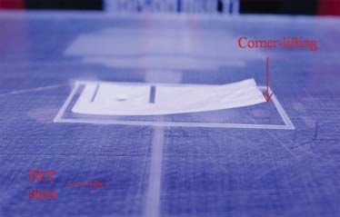
CMC, 2021, vol.68, no.3                                                                     2919

mouse-ear brim) were cut off without trouble after finishing the fabricating procedure. Conse-
quently, using the proposed fabricating schematic diagram, the current FDM-printed models were
fabricated adequately and did not require modification. It is worth noting that the values in the
column “Values for typical samples” in Tab. 1 are the default values of the manufacturer of
the printing machine. The values in the column “Values for improved samples” in Tab. 1, which
include temperatures and printing speed, are those from the proposed nine steps mentioned above.
A lower infill was chosen because less material led to a need for less shrinking of material. An
infill of 60% was determined from preliminary experiments to be enough for the printed mold
core to be utilized in the thermoforming apparatus.

                               Table 1: Parameters for 3D printer
Parameters                  Units       Values for typical samples Values for improved samples
Filling rate                %           90                          60
Layer height                mm          0.2                         0.2
Nozzle diameter             mm          0.4                         0.4
Thickness of shell          mm          0.4                         0.4
Top and bottom thickness    mm          0.6                         0.6
Feed rate                   %           97                          97
Output speed                mm × s−1    80                          60
Shell speed                 mm × s−1    50                          30
Floor layer speed           mm × s−1    50                          20
Output temperature          ◦C          260                         250
Heat bed temperature        ◦C          120                         110
First layer thickness       mm          0.3                         0.3

Figure 7: Two representative printed samples: (a) Previous sample with large corner lifting after
printing, and (b) better sample printed by utilizing preprocessing
2920 CMC, 2021, vol.68, no.3
An additional benefit from the proposed sequence was the quality of the sole layer. It was
improved significantly due to the gloss surface of the Kapton tape. The sole layers of the printed
samples for the initial small-size parts are shown in Fig. 8 compared with a purchased PET sheet
and new Kapton tape. The appearance of the sole layer is such that it does not significantly affect
the functions of the sample as a mold core in a thermoforming process. This aesthetics can be a
reason for the proposed sequence to be utilized in other processes.
It is worth noting that in the initial steps, using the default polyethylene terephthalate (PET)
sheet for the printing bed, the machine could not finish the printing task using ABS filaments
due to a poor adhesion problem. The warpage was around 3.7 mm using a polyimide film. The
maximum warpage was around 0.8 mm after improvement, which is considered suitable for the
use of a mold core in a thermoforming process [38,39].
Figure 8: The sole layers of two printed samples: Previous sample with the PET sheet, and
improved sample utilizing Kapton tape
4 Concluding Remarks
In the present study, the warpage phenomenon, which is commonly observed in the FDM
process for relatively large parts, was investigated. An improved part with reduced corner lifting
was efficiently produced after consideration of thermal effects and adhesion force. Nine important
results are highlighted that serve as guidelines to utilize a 3D printing machine to develop a
new type of mold core for processes like thermoforming that incorporate heating. Our study
differs from previous investigations in that it not only addresses the processing parameters of the
warpage problem but more widely examines all relevant processes including pre-processing and
processing parameters. After improvement, the maximum corner-lifting was around 0.8 mm, which
is considered suitable for the use of a polymer mold core in a thermoforming process. Mouse ears
brims, as well as additional ABS glue, can be removed easily after the printing process has been
completed. The techniques used therefore did not affect the quality of the printed parts.CMC, 2021, vol.68, no.3 2921
Funding Statement: The work presented in this study was orally presented at the first China–
Vietnam symposium on precision manufacturing–CVPMS 2018, Industrial University of Ho Chi
Minh City in Vietnam.
Conflicts of Interest: The authors declare that they have no conflicts of interest to report regarding
the present study.
References
[1] T. K. Nguyen and B. K. Lee, “Minimization of corner lifting phenomena in fused deposition
modeling,” in Proc. KSMPE Annual Autumn Conf., Sacheon, Korea, pp. 78–85, 2015.
[2] B. Wiedemann, K. H. Dusel and J. Eschl, “Investigation into the influence of material and process on
part distortion,” Rapid Prototyping Journal, vol. 1995, no. 1, pp. 17–22, 1995.
[3] T. M. Wang, J. T. Xi and Y. Jin, “A model research for prototype warp deformation in the FDM
process,” International Journal of Advanced Manufacturing Technology, vol. 2007, no. 33, pp. 1087–
1096, 2007.
[4] Y. Zhang and K. Chou, “A parametric study of part distortions in fused deposition modelling using
three-dimensional finite element analysis,” Proceedings of the Institution of Mechanical Engineers, Part B:
Journal of Engineering Manufacture, vol. 2008, no. 222, pp. 959–968, 2008.
[5] A. K. Sood, R. K. Ohdarand and S. S. Mahapatra, “Improving dimensional accuracy of fused
deposition modelling processed part using grey Taguchi method,” Materials & Design, vol. 2009, no. 30,
pp. 4243–4252, 2009.
[6] S. K. Panda, S. Padhee, A. K. Sood and S. S. Mahapatra, “Optimization of fused deposition modelling
(FDM) process parameters using bacterial foraging technique,” Intelligent Information Management,
vol. 2009, no. 1, pp. 89–97, 2009.
[7] S. Saqib and J. Urbanic, “An experimental study to determine geometric and dimensional accuracy
impact factors for fused deposition modelled parts,” in Enabling Manufacturing Competitiveness and
Economic Sustainability, Berlin, Germany, Berlin Heidelberg: Springer, pp.293–298, 2012.
[8] B. N. Turner, R. Strong and S. A. Gold, “A review of melt extrusion additive manufacturing processes:
Process design and modeling,” Rapid Prototyping Journal, vol. 2014, no. 20, pp. 192–204, 2014.
[9] R. Yeu, N. Ra, S. Lee and Y. Nam, “Evaluation of pencil lead based electrodes for electrocardiogram
monitoring in hot spring,” Computers, Materials & Continua, vol. 66, no. 2, pp. 1411–1425, 2021.
[10] A. U. Rehman, F. Ali, A. Aamina, A. Imitaz, I. Khan et al., “An unsteady oscillatory flow of
generalized casson fluid with heat and mass transfer: A comparative fractional model,” Computers,
Materials & Continua, vol. 66, no. 2, pp. 1445–1459, 2021.
[11] A. U. Khan, N. Ahmed, S. T. Mohyud-Din, I. Khan, D. Baleanu et al., “Al2 O3 and γ Al2 O3
nanomaterials based nanofluid models with surface diffusion: Applications for thermal performance
in multiple engineering systems and industries,” Computers, Materials & Continua, vol. 66, no. 2,
pp. 1563–1576, 2021.
[12] N. L. Chau, T. P. Dao and V. T. T. Nguyen, “Optimal design of a dragonfly-inspired compliant joint
for camera positioning system of nanoindentation tester based on a hybrid integration of Jaya-ANFIS,”
Mathematical Problems in Engineering, vol. 2018, pp. 1–17, 2018.
[13] N. L. Chau, T. P. Dao and V. T. T. Nguyen, “An efficient hybrid approach of finite element method,
artificial neural network-based multiobjective genetic algorithm for computational optimization of a lin-
ear compliant mechanism of nanoindentation tester,” Mathematical Problems in Engineering, vol. 2018,
pp. 1–19, 2018.
[14] T. V. T. Nguyen, N. T. Huynh, N. C. Vu, V. N. D. Kieu and S. C. Huang, “Optimizing compliant grip-
per mechanism design by employing an effective bi-algorithm: Fuzzy logic and ANFIS,” Microsystem
Technologies, vol. 2021, pp. 1–29, 2021.2922 CMC, 2021, vol.68, no.3
[15] Z. Chen, V. T. Nguyen and N. T. Tran, “Optimum design of the volute tongue shape of a low specific
speed centrifugal pump,” Journal of Electrical & Electronic Systems, vol. 2017, pp. 1–5, 2017.
[16] T. A. Tarray, Z. A. Ganie and B. Youssuf , “An improved mathematical model applying practicable
algorithms,” Journal of Applied Science, Engineering, Technology, and Education, vol. 1, no. 2, pp. 114–
118, 2020.
[17] J. Sadoon and B. B. Üstündağ, “Fused and modified evolutionary optimization of multiple intelligent
systems using ANN, SVM approaches,” Computers, Materials & Continua, vol. 66, no. 2, pp. 1479–
1496, 2021.
[18] A. A. Abdallah, “How can lean manufacturing lead the manufacturing sector during health pandemics
such as Covid 19: A multi response optimization framework,” Computers, Materials & Continua, vol. 66,
no. 2, pp. 1397–1410, 2021.
[19] K. Vikram, U. Ragavendran, K. Kalita, R. K. Ghadai and X. Gao, “Hybrid metamodel—NSGA-III—
EDAS based optimal design of thin film coatings,” Computers, Materials & Continua, vol. 66, no. 2,
pp. 1771–1784, 2021.
[20] A. Peng, X. Xiao and R. Yue, “Process parameter optimization for fused deposition modeling using
response surface methodology combined with fuzzy inference system,” The International Journal of
Advanced Manufacturing Technology, vol. 2014, no. 73, pp. 87–100, 2014.
[21] B. N. Turner and S. A. Gold, “A review of melt extrusion additive manufacturing processes: Materials,
dimensional accuracy, and surface roughness,” Rapid Prototyping Journal, vol. 2015, no. 21, pp. 250–
261, 2015.
[22] F. R. Jose, P. T. James and E. R. John, “Characterization of the mesostructured of-deposition
acrylonitrile-butadiene-styrene materials,” Rapid Prototyping Journal, vol. 2000, no. 6, pp. 175–186, 2000.
[23] Antonio Armillotta, Mattia Bellotti and Marco Cavallaro, “Warpage of FDM parts: Experimental tests
and analytic model,” Robotics and Computer-Integrated Manufacturing, vol. 50, pp. 140–152, 2018.
[24] C. K. Chua, K. F. Leong and C. S. Lim, Rapid Prototyping: Principles and Applications, 2nd ed.,
Singapore: World Scientific, 2003. [Online]. Available: https://www.worldscientific.com/worldscibooks/
10.1142/5064.
[25] B. N. Turner and S. A. Gold, “A review of melt extrusion additive manufacturing processes: II.
Materials, dimensional accuracy, and surface roughness,” Rapid Prototyping Journal, vol. 21, no. 3,
pp. 250–261, 2015.
[26] J. F. Rodríguez, J. P. Thomas and J. E. Renaud, “Design of fused-deposition ABS components for
stiffness and strength,” Journal of Mechanical Design, vol. 2003, no. 125, pp. 545–551, 2003.
[27] I. Gibson, D. Rosen and B. Stucker, Introduction and Basic Principles, Additive Manufacturing Technolo-
gies: 3D Printing, Rapid Prototyping, and Direct Digital Manufacturing, vol. 2015. New York: Springer,
pp. 1–18, 2015.
[28] O. A. Mohamed, S. H. Masood and J. L. Bhowmik, “Optimization of fused deposition modeling
process parameters: A review of current research and future prospects,” Advances in Manufacturing,
vol. 2015, no. 3, pp. 42–53, 2015.
[29] D. Annicchiarico and J. R. Alcock, “Review of factors that affect shrinkage of molded part in injection
molding,” Materials and Manufacturing Processes, vol. 2014, no. 29, pp. 662–682, 2014.
[30] T. K. Nguyen and B. K. Lee, “Surface morphology and roughness of fused deposition modelled parts
during a novel post-processing technique,” in Proc. KSPE Annual Spring Conference, vol. 2016, pp. 50–
51, 2016.
[31] T. K. Nguyen, A. D. Pham, M. Q. Chau, X. C. Nguyen, H. A. D. Pham et al., “Development and
characterization of a thermoforming apparatus using axiomatic design theory and Taguchi method,”
Journal of Mechanical Engineering Research and Developments, vol. 43, no. 6, pp. 255–268, 2020.
[32] Y. Lutfiansyah and G. Tanjung, “Cost comparison analysis of slab structure using concrete beam and
steel beam,” Journal of Applied Science, Engineering, Technology, and Education, vol. 2, no. 1, pp. 88–96,
2020.CMC, 2021, vol.68, no.3 2923
[33] A. T. Munthe and A. Gafur, “Comparative analysis study of ATC-40 and SNI 1726-2012 guidelines for
beam structure performance and column trans studio apartments applications using dynamic response
spectrum analysis methods,” Journal of Applied Science, Engineering, Technology, and Education, vol. 1,
no. 1, pp. 46–55, 2019.
[34] D. Essen and L. Luqyana, “Analysis and dynamic behavior of portal structure due rotating machines
loads,” Journal of Applied Science, Engineering, Technology, and Education, vol. 1, no. 2, pp. 131–
140, 2020.
[35] R. V. V. R. Murthy, K. S. R. Murthy and M. Chavali, “Design and development of instant linear gel
for coal bed methane gas operations,” Journal of Applied Science, Engineering, Technology, and Education,
vol. 3, no. 2, pp. 217–223, 2020.
[36] S. Niknamian, “Investigation on the effect of cold drawing process on mechanical properties and struc-
ture of seamless steel (Ck60) tube,” Journal of Applied Science, Engineering, Technology, and Education,
vol. 1, no. 1, pp. 13–23, 2019.
[37] A. B. Fakhri, S. L. Mohammed, I. Khan, A. S. Sadiq, B. Alkazemi et al., “Industry 4.0: Architecture
and equipment revolution,” Computers, Materials & Continua, vol. 66, no. 2, pp. 1175–1194, 2021.
[38] T. K. Nguyen and B. K. Lee, “Post-processing of FDM parts to improve surface and thermal
properties,” Rapid Prototyping Journal, vol. 24, no. 7, pp. 1091–1100, 2018.
[39] T. K. Nguyen and B. K. Lee, “Investigation of processing parameters in micro-thermoforming of
micro-structured polystyrene film,” Journal of Mechanical Science and Technology, vol. 33, no. 12,
pp. 5669–5675, 2019.You can also read