Modular Function Deployment - Using Module Drivers to Impart Strategies to a Product Architecture1
←
→
Page content transcription
If your browser does not render page correctly, please read the page content below
Chapter 4 Modular Function Deployment – Using Module Drivers to Impart Strategies to a Product Architecture 1 Mark W. Lange and Andrea Imsdahl Abstract Products reflect the needs of many different entities. People such as end-users and re-sellers, regulating bodies of authority, and individuals within manufacturing and engineering provide statements as “voices” that impact the physical structure of a product in different ways. A company establishes a strate- gy to realize the product that responds to these “voices”. There are various ap- proaches to capturing a singular “voice of x” when realizing a product architec- ture. Modular Function Deployment differs from other architecture methods by providing a holistic approach to capturing multiple “voices” as a company strategy through the use of Module Drivers. This approach is demonstrated by actual in- dustrial examples that explore the flexibility of Module Drivers applied in the cre- ation of a conceptual modular product architecture. 4.1 Introduction To compete in today’s global marketplace, many companies are utilizing product families to increase variety, improve customer satisfaction, shorten lead-times, and reduce costs (Simpson et al. 2006). Product families and synonymously, product platforms and product architec- tures, are showing themselves to be a tactic of enabling strategic objectives. The industrial community is reporting on the successes achieved through the systemat- ic application of product architecture that support the idea of how useful product Mark W. Lange () Andrea Imsdahl Modular Management USA, Inc., Bloomington, MN 55425, USA e-mail: mwlange@msn.com
2                                                   Mark W. Lange and Andrea Imsdahl

architectures are for enabling strategic intent. There is a relationship between a
product family and the product development. The product development process is
the tactical vehicle to convey the business strategy or strategic objectives of im-
proving customer satisfaction, shorten lead-times, and reduce costs through the
application of a product family.
   Devising a means to model the relationship between the product development
process and strategic business objectives would make it easier to explain how in-
dustrial companies could benefit from a modular product architecture. Naturally,
the model needs to be adaptable not only for different business strategies driven
by a product type or industry, but also adaptable to strategies that evolve with
product maturity and new market emergence.
   Modular Function Deployment (Ericsson and Erixon 1999) is the method
Modular Management uses to illustrate the relationship between product architec-
ture and strategic objectives with the use of Module Drivers. Our suggestion is
that by using Module Drivers, strategy can be imparted on the product architec-
ture.
   In the following sections this topic will be developed. First, a brief study of
product platform strategy and its role in the development of product architectures
will position the development of our approach. Then a model of how Module
Drivers impart strategy is constructed and explained. Based on our extensive data-
base of modular product platforms, the model will be demonstrated using a num-
ber of industrial product architecture results. Finally, we will discuss some in-
sights learned from the model’s application and directions of continued research.

4.2      Background

4.2.1 Strategy and Tactics in Product Development

There is an inherent relationship between strategy and tactics, particularly in
Product Development. Where strategy is the idea of an objective that can be real-
ized through the application of a plan, tactics is then the execution and assessment
of the outcome of that plan. For example, strategy is found in the idea of selecting
between three product development approaches to tactically develop a product
platform, as described in (Hölttä and Salonen 2003). However, joining the idea of
a strategic objective with the tactical outcome is often inferred, even when the ev-
idence of strategy can be found in the tactical results, like when describing how
product platforms are being tactically leveraged by market strategies, from (Mari-
on and Simpson 2006).
   However, let us take note of the observation that product platforms and product
families are being utilized to realize several business objectives; increase variety,
4 Modular Function Deployment                                                    3

Fig. 4.1 The value dis-
ciplines abstractly rep-
resented in a three di-
mensional space.

improve customer satisfaction, shorten lead-times, and reduce costs. The strategy
of a business is not to realize a product platform; product platforms and product
families are a tactical means to operating a business.
   When we talk about business strategy we are referring to how businesses are
managed (Treacy and Wiersema 1995). For example, a business strategy is based
on an idea of what is the company going to promise its customers and then it de-
velops a plan to bring the fulfillment of the promise to the customers, which
should be an activity in a product planning process (Bowman 2006). Treacy and
Wiersema call the first part of a business strategy the Value Proposition and the
second part the Value-Driven Operating Model. These two parts are combined to
form the desired way of managing a business, the Value Discipline. There are
three Value Disciplines available to a business strategy; Product Leadership, Op-
erational Excellence and Customer Intimacy as shown in Fig. 4.1. Typically, a
business will pick one of these value propositions as its main focus and then seek
to reach a minimum level with the other two (Nightingale and Srinivasan 2011).

4.2.2 Module as a Tactical Vehicle

In reviewing the literature on product platforms, product families and product ar-
chitectures, the concept of a module appears regularly as a tactical vehicle in new
product development. The concept of a module has been labeled as a “system par-
tition” (Christopher 1964), “structural element” (Baldwin and Clark 2000),
4                                                    Mark W. Lange and Andrea Imsdahl

    Fig. 4.2 Product Manage-
    ment Map (PMM), where
    the Module Indication Ma-
    trix (MIM) and Module
    Drivers are the objects of
    this article.

“chunk” (Ulrich and Eppinger 2008) or “building block” (Vos 2001). Definitions
for these concepts typically reference at least one of the following three key con-
ceptual attributes,
     a) what the module contains; responding to a Voice of Customer perspective
         that the module will contain a function bearing technical solution that is
         identified as benefiting the customer,
     b) what the physical limits of the module are; representing the Voice of
         Engineering in its need to manufacture modules so that they properly fit
         together, and
     c) why the module exists; reflecting the Voice of Business in configuring a
         product variant using the module.
     Modular Function Deployment however promotes a definition of a modular
that reflects all three Voices by stating that a module is a functional building block
with specified interfaces, driven by company-specific reasons (Erixon 1998).

4.2.3 Modular Function Deployment

Since 1996, Modular Management has provided the service of developing modu-
lar product architectures using a systematic method called Modular Function De-
ployment (MFD). At the start of every MFD project a core project team is identi-
fied. It is essential for the core team to be cross-functional, which has been
clarified by (Kono and Lynn 2007) and (Wheelwright and Clark 1995). Cross-
functional teams are comprised of representatives that personify their area of re-
sponsibility and experience respectively as the Voice of Customer, Voice of Engi-
neer, and Voice of Business. Collectively these personas are referred to as “Voices
of X”, or “VoX”. Cross-functional teams are flexible with a strong project focus.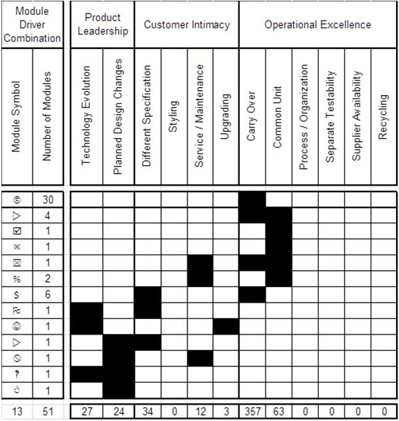
4 Modular Function Deployment                                                     5

Fig. 4.3 Modular Function Deployment, adapted from (Erixon 1998).

They also bring a breadth of knowledge which can yield an integrated system so-
lution that is not always achievable in functional or departmental teams.
    These “Voices of X” are the spoken and unspoken needs, expectations, prefer-
ences, and wants of the people who constitute a given entity. Voice of Customer
is a key input for product definition and the setting of a product’s value proposi-
tion. This voice is typically represented by the sales and/or marketing function.
Voice of Engineering collects inputs from engineering, manufacturing, after-
market, etc. for the execution of the value driven process to design an appropriate
product for the customer. A company’s engineering, research and design, and
manufacturing functions define this voice. Voice of Business are shareholders,
corporate officers, or others involved in corporate governance who determine
which value discipline is crucial to the success of not only the product but the
business as a whole. Project manager, platform manager, and product managers
represent the Voice of Business for a Modular Function Deployment project.
    Modular Function Deployment organizes the product data, information and
knowledge gathered by the core team into a collection of matrices known as the
Product Management Map (PMM), shown illustrated in Fig. . Each voice is
captured in a different matrix to generate the modular product architecture.
Iterations are necessary at each step to manage the trade-offs between the different
voices.
    MFD is composed of five basic steps (Erixon 1998), illustrated in Fig. 4.. The
first step is represented in the Quality Function Deployment (QFD) matrix that
clarifies the customer requirements (aka customer value statements) by mapping
them against the product properties. Product properties are measureable and
controllable entities that allow specification of the product demanded by the
customer. QFD captures the Voice of Customer and allows it to influence the
design of the product at the proper level of abstraction.
    The functional requirements of the product are established with the use a form
of functional decomposition. Functional decomposition is then utilized to define
the technical solutions. Technical solutions are the embodiment of the product
properties. If necessary a Pugh process can be used to evaluate and evolve tech-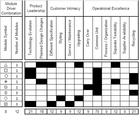
6                                                            Mark W. Lange and Andrea Imsdahl

Fig. 4.2 Module drivers positioned along a product lifecycle stream.

nical solutions based on evaluation criteria (i.e. Product Properties) generated in
Step 1 of Modular Function Deployment in addition to internal considerations
such as part number count and production goals. The results of these decisions are
modeled in a Design Property Matrix, first presented in (Nilsson 1998), which
documents the relationship between product properties and technical solutions.
DPM then becomes the representation of the Voice of Engineering.
   Step three highlights a unique attribute of Modular Function Deployment. Un-
like other architecting approaches, MFD incorporates a company’s strategic intent
into the product design. Module Drivers are the mechanism used to indicate the
strategic reason a module should be created. There are twelve Module Drivers
which cover the entire life cycle of a product. A driver is applied to a technical
solution in the Module Indication Matrix (MIM) to impart the strategy the compa-
ny has for a Technical Solution being the foundation of a Module. Clustering the
MIM and DPM, module concepts are generated therefore capturing the Voice of
Business.
   The module concepts are evaluated in step four by considering how the mod-
ules will be physically joined together using standardized module interfaces. In-
terfaces represent an agreement or contract (Baldwin and Clark 2008) between
modules in a product architecture. Evaluation of the interfaces is vital to ensure
flexibility of the product assortment as well as allowing for concurrent engineer-
ing. The Modular Function Deployment process considers seven basic types of
interfaces. An interface can be defined as an attachment, transfer, spatial, com-
4 Modular Function Deployment 7
mand and control, field, environmental and user. An interface matrix documents
the interface type and facilitates the analysis of interfaces.
Finally step 5 improves on the module concept with DFX approaches, for ex-
ample Design for Manufacturing and Assembly, depending on the company value-
driven operating model. Module specifications are written for each module con-
taining market requirements, technical information, and business strategy. MFD is
not a replacement for component level design improvements. Detail design of the
components encapsulated in a module is still required and guided by the module
specifications.
4.2.4 Module Drivers
Early during the development of Modular Function Deployment, research was
conducted in industry to determine the heuristics product designers applied when
creating modules by contacting a number of companies who promoted their prod-
ucts as modular. The resultant twelve heuristics were reported by (Östgren 1994)
and called “Module Drivers”. Module Drivers are found to cover the entire prod-
uct lifecycle from introduction to growth, maturing, and decline. Module Drivers
also cover a wide spectrum of “Voices of X” as the product moves through its
lifecycle, as illustrated in Fig. 4.2. This coverage ensures that all stakeholders in
the product have a voice as well as a way to document their particular strategic in-
tent. Because Module Drivers are seen as generic heuristics, a project team may
introduce new or modified heuristics which are company specific such as financial
caps, geographical constraints, governmental regulations, etc.
The “Voice of Customer” reflects the need that a product platform embodies
variance. Variation should be contained in as few areas of the product as possible
to be managed effectively and minimize disruptions to the whole product when in-
troducing new variants. Delaying variation adaptation as long as possible in the
production chain decreases lead times, improves supply chain, and lowers overall
costs. Two Module Drivers are available to describe the Voice of Customer vari-
ance in the product architecture,
“Different Specification” is used to impart the strategic need for technical per-
formance variance in the product platform. Language and culture demands can
change the label for the concept of the Module Driver to be referred to as
“Technical Specification”.
“Styling” imparts the strategic need for brand driven appearance variance in
the product platform.
Concerns with product planning and design are spoken through the “Voice of
Engineering”. Engineering addresses the needs to manage modules of the archi-
tecture that will or will not change during the platform’s lifetime in addition to
modules that will go through a technology shift based on changing customer de-
mands. There are three Module Drivers to address engineering perspectives,8 Mark W. Lange and Andrea Imsdahl
“Carry Over” imparts strategies of technology re-use across generations of the
product platform
“Technical Evolution” imparts the strategic development of technology driven
by external forces outside the company. Language and culture demands can
also re-label the concept of this driver as “Technology Push”.
“Planned Design Changes” imparts company internal strategies to launch new
products, meet changing customer requirements, or decrease product costs. An
alternative name for the driver is “Planned Development”.
The “Voice of Manufacturing” strives to maintain a consistent, effective and ef-
ficient manufacturing process. Two Module Drivers that strengthen this approach
are,
“Common Unit” imparts the strategy that a required function must have the
same physical form in principally every product variant
“Process and/or Organization” imparts the strategy that there is a suitable col-
lection of technology driven work content for a manufacturing cell or work
group to support a uniquely efficient process
“Voice of Quality” seeks to improve the manufactured quality of a product. In-
creasing quality decreases the loss from warranty and product liabilities by de-
creasing quality feedback time. To address this concern the following Module
Drive is applied.
“Separate Testability” or “Separate Testing” imparts strategies where functions
can be tested independently of the product
“Voice of Supply Chain” provides manufacturing with the raw material and
components it needs to build the product a customer desires. At times it will be
critical for an outside vendor to provide a company with standard modules or
black box modules. Black Box modules are modules in which a vendor takes total
responsibility in terms of development, manufacture, and quality assurance. Typi-
cally vendors of black box modules are specialists in a given technology and a
company can leverage this expertise with the use of this Module Driver;
“Supplier Availability” imparts strategies for outsourcing “black box” technol-
ogy in a module. Alternatively, this driver is re-labeled as “Strategic Supplier”
or “Strategic Supplier Available”.
The addition of non-factory accessories, parts, service or upgrades refers to the
“Voice of After-Market”. This stage of the lifecycle occurs once the product has
been released to the marketplace. Sometimes these services are offered by the
company that manufactures the product and other times these services are made
possible by an unrelated entity. The following three Module Drivers support this
Voice of X;
“Service and Maintenance” imparts strategies where service on a product in the
field is an important customer value. The driver is also known as Serviceabil-
ity.
“Upgrading” imparts strategies that will extend product life or improve product
performance4 Modular Function Deployment 9
“Recycling” imparts strategies that enable codes regarding the disposal of haz-
ardous as well as homogenous materials
The concept of a design strategy represented as a Module Driver for selected
Product Lifecycles is not limited to just these 12 Module Drivers. Additional driv-
ers can be added to this generic set depending on the industry and product type.
An example of the addition of a Module Driver can be found for the medical in-
dustry that develops and markets test equipment that is required to certify sub-
systems with the Food and Drug Administration for products sold in the US mar-
ket. A product architecture developed for a company in this industry may well use
a “Regulations Compliant” Module Driver. A similar Module Driver is also useful
in the specialty vehicle industries that develop motor vehicles for over-the-road
use in Europe and North America, because road certification is different in Europe
contra North America.
4.3 Approach
4.3.1 Imparting Strategy with Module Drivers
Module Drivers are the information objects used to bridge the business strategy
with the product architecture and often several Module Drivers are applied to indi-
cate several strategic objectives. There are combinations of Module Drivers that
are compatible, which allow them to work together to enhance a module’s strate-
gy. For example, two objectives for creating a product platform are to shorten
lead times and reduce costs. The compatible pair of Common Unit and Carry
Over addresses both of these goals in a single module. By carrying over the mod-
ule, lead times are reduced since no time is spent on redesigning or updating the
module from one product generation to the next. Common Unit modules are typi-
cally high volume modules and therefore attain a sourcing discount. Together the
drivers create a coherent strategy.
A second compatible set of drivers is Service and Maintenance and Separate
Testability. Service and Maintenance modules are structured in such a way when
the module stops functioning it can be removed from the product in its entirety
and replaced with a fully functional new module. If the module is also Separate
Testability, service can be conducted on the dysfunctional module to discover if
the module can be repaired. This combination improves customer satisfaction and
reduces cost by preventing extended downtimes.
Separate Testability is also compatible with Supplier Availability. Since Sup-
plier Availability modules are black box engineered by the supplier, companies
can verify the quality of these modules by testing them prior to assembly. This
shortens lead times and reduces costs.10 Mark W. Lange and Andrea Imsdahl There are also conflicting drivers. These are Module Driver combinations whose strategies are mutually exclusive. Both Technical Evolution and Planned Design Change state that the content of the module will change over time, where the content of Carry Over modules will not change over time. With differing per- spectives on time, Technical Evolution and Planned Design Change should not be used in conjunction with Carry Over for any given module. Styling and Different Specification are drivers which indicate high variance modules. Common Unit on the other hand is a driver for modules where there is no variance. These drivers have conflicting strategies and should not be used in combination with each other. The last set of conflicting drivers is Technical Evolution and Process and/or Organization. Technical Evolution modules have content that is evolving due to external sources. Process and/or Organization modules reuse a specific manufac- turing process. The idea of reuse and change conflict with each other and should not be combined in the same module. To illustrate the application of Module Drivers, imagine a laptop. A laptop is a collection of modules each with its own strategy. Take the screen for example. Screens are offered in sizes ranging from 12 inches to 17 inches. Each size offers a distinguishable performance to the customer. In contrast to the laptop, an iPad® is currently only available in one screen size. The screen, as a module, has there- fore been imparted with the Common Unit driver as a business strategy. Another example of Different Specification is the battery. A battery offered in a laptop can be available in two different performance levels; regular life and ex- tended/heavy duty life. Depending on a consumer’s use of the laptop, say some- one who travels on a plane regularly, they would buy a battery with extended life so that during a flight they can work for hours without having to recharge. On the other hand, someone who only checks e-mail and surfs the web for an hour or so at night has their needs met with a regular life battery. Therefore battery supports Different Specification to meet the needs of both customers. Battery packs found in a typical laptop can be replaced in the event the battery will no longer hold a charge. This capability would be imparted by the Service and Maintenance driver for a business strategy. However, consider the current generation of e-readers and tablets. If the battery in these devices no longer charg- es, the battery in the unit cannot be replaced by the consumer. This reflects a busi- ness strategy for the product architecture that does not include Service and Maintenance on the battery. The laptop and e-readers / tablets use their case as a style design element in the architecture. Apple® has trademarked the iPad® white case with clean simple lines. It is the look that Apple® has become known for. With the introduction of the iPhone, iPads now also come in black. Similarly, laptops allow a customer to purchase a case in any color of the rainbow. This choice is imparted by applying the Styling driver. The hinge, USB, and power button are all examples of Common Unit and Car- ry Over. Each of these modules has a single module variant that is used across the
4 Modular Function Deployment                                                    11

entire platform of laptops. Regardless if laptop has a 15” screen with regular bat-
tery life or a 17” screen with extended battery life, the hinge, USB, and power but-
ton will always be the same. While the presence of these modules is essential to
the function of a laptop, none bring a tremendous amount of value to the customer.
And none will be undergoing a technology shift during the lifetime of the plat-
form. Therefore these modules also embody a Carry Over strategy.
    Similar to the hinge, USB, and power button a laptops latch is also a Common
Unit. It too comes in a single module variant used across all models of the prod-
uct platform. Unlike the previous modules, the latch is not carried over from one
product generation to the next. Instead the latch is part of the style of the laptop
case. As industrial engineers update the form of the laptop the latch will change.
Therefore the strategy of the latch is Common Unit and Styling.
    Laptop microprocessors are a technology that laptop manufacturers typically do
not design for themselves. The microprocessor is an example of black box engi-
neering. The laptop manufacturers would be unable to produce the laptop without
the microprocessor supplier. This is a strategic relationship between the compa-
nies and therefore a Supplier Availability module.
    With a limited number of microprocessor manufacturers there is a significant
amount of competition to produce the fastest, most reliable microprocessor. Mi-
croprocessors are rapidly changing to exceed the expectation of customers. To
stay in line with the latest technology laptop companies decide if they want to en-
able their product architecture to handle these constant changes. If they want to
offer their customers the best of what is available from the external sources, the
microprocessor will also become a Technical Evolution module.
    Web-cams are becoming more common in laptops and tablets. For the laptop
producer, the web-cam will be a Technical Evolution module. However, within
this web-cam there is a chip that is being developed to capture images in ever in-
creasing resolutions. For the chip manufacture this technical solution with be im-
parted with the driver Planned Design Change.
    If a laptop company designs their own hard drives, it may be advantageous for
them to increase after-market sales with an Upgrading strategy. Allowing a cus-
tomer to transition from a 250GB hard drive to a 500GB or even a 1TB hard drive
as their storage needs change. The customer will not have to buy a new laptop to
gain the extra storage and the company will still maintain the sales revenue by
selling the higher capacity hard drive.
    Hard drives require a clean room environment during their assembly. Any par-
ticles that are introduced may interfere and destroy the operation of the hard
drive’s intricate componentry. Process and/or Organization would collect the
components into a module for an efficient, high quality process.
    The final module is the motherboard. This module employs both Separate
Testability and Recycling. Motherboards are an expensive and integral compo-
nent of a laptop. Separate Testability offers quality feedback prior to the assembly
of the motherboard to the case. In the event of a quality issue, the impact is con-
tained to the motherboard only. No additional modules will need to be scraped.
12 Mark W. Lange and Andrea Imsdahl
Fig. 4.3 Value disciplines
shown with the aligned
module drivers.
Motherboards contain materials that require special handling at the end of life
of a laptop. The ability to remove the motherboard from the rest of the machine
ensures that that module will be disposed of properly. This strategy is enabled by
the Recycling driver.
4.3.2 Aligning Module Drivers to Value Disciplines
As information objects used to bridge business strategy with a product architec-
ture, the application of Module Drivers impart business strategies that align with
the Different Value Disciplines.
Product Leadership companies are creative, commercialize their products
quickly, and constantly try to outdo themselves. The value proposition for a prod-
uct leader is to offer their customers the best product imaginable. The module
drivers that substantiate the value proposition are Technical Evolution and
Planned Design Change. Product leaders are constantly reinventing themselves.
They are not concerned if the changes are external or internal. They will lead the
market regardless.
Customer Intimacy companies rely on building customer loyalty. These com-
panies are not directly focused on a product that a market segment wants. Instead
they are interested in the product a specific customer wants. The value proposi-
tion for Customer Intimacy is selling the best total solution from product to ser-
vices. Different Specification, Styling, Service and Maintenance, and Upgrading
all increase a company’s ability to offer the total package to a customer. Different
Specification and Styling manage the customer specified variance, where Service /4 Modular Function Deployment 13 Maintenance and Upgrading manage the services provided once the customer has purchased the product. These drivers manage the total solution. Operational Excellence companies are not service or product innovators. They do not build profound relationships with their customers. The value proposition for an operationally excellent organization is to provide their customers the best priced products with the least inconvenience. The module drivers that reinforce the proposition are Carry Over, Common Unit, Process and/or Organization, Sepa- rate Testability, Supplier Availability, and Recycling. Each of these drivers’ aides a manufacturing company in focusing on streamlining processes, reducing set-up times, and strengthening the supply chain. Reducing the cost of producing a product enables an attractive price point being offered to the customer with supe- rior customer service. The alignment of the Module Drivers to the Value Disciplines, as discussed, is shown in Fig. 4.3 by treating each Value Discipline as an Eulerian circle. These alignments can be adjusted if the business strategy of company varies from the generic model. An example is found in the Module Driver for Recycling. One business strategy might place the Recycling driver along the Customer Intimacy to impart the idea that the module can be recycled by the end user as part of a “green” strategy. Another business strategy might place the Module Driver along the Operational Excellence to impart the idea of material purity in the module. 4.3.3 Illustrating the Module Driver Profile During Step 3 of a Module Function Deployment program, a project team com- pletes the Module Indication Matrix by assigning Module Drivers to the Technical Solutions selected to be included in the architecture or platform using a scale of 9, 3, or 1. A score of 9 when applying a Module Driver represents a strong strategic interest, a 3 has a medium level of interest and a 1 has little strategic interest (but there is enough to make a difference). The scoring data is recorded in a database tool called PALMA (Product Architecture Lifecycle Management). Each application of Modular Function Deployment that results in a module sys- tem is captured in a PALMA database that allows the results of the first three steps to be presented as a set of three linked two-dimensional matrices, also called the Product Management Map, shown in Fig. . For this approach we will extract the third matrix for examination, the Module Indication Matrix that illustrates the rela- tionships between the Modules and the Module Drivers. After discussion with the company, the Module Drivers are sorted into a com- pany specific Value Discipline that follows the general definitions, as illustrated in Fig. 4.3. These same alignments are performed on the Module Drivers in the Module Indication Matrix. Aligning the module drivers to the strategic axes offers a unique ability analyze the Module Driver profile for the product platform and es- tablish the existence of alignment between the corporate strategy i.e. value disci-
14                                                       Mark W. Lange and Andrea Imsdahl

Fig. 4.4 Screenshot of the PALMA application that shows the Module Indication Matrix.

pline and the project team strategy. The Module Driver profile is the unique com-
bination of Module Drivers and can be found on Modules as well as on a whole
architecture.
   In the first iteration of a Module Indication Matrix it is difficult for the project
team to commit to a single driver. Typically different voices are in conflict over
the strategic intent of the module. Marketing would prefer to have a module with
a high number of variants that change with each product generation, but Manufac-
turing wants to standardize on a single solution that remains unchanged. In some
cases the project team views their corporate strategy differently than upper man-
agement. Many engineering teams believe that they are product leaders when in
reality the organization has a strong focus on operational excellence. Multiple it-
erations on the Module Indication Matrix are required to reconcile these conflicts
and simplify the strategy.
   Allowing only a primary and possibly a secondary strategy reduces the com-
plexity of a module’s design and simplifies the module driver profile. Think of it
in terms of driving a car; would you want more than one person driving a car? A
co-pilot comes in handy but add a backseat driver and the ride can become prob-
lematic. As with driving a car, multiple module drivers lead to complications in
the management of the architecture. Harmonizing a module’s strategy is critical
to the longevity and success of the product platform. Module Drivers capture all
4 Modular Function Deployment                                                    15

Fig. 4.5 Value Discipline
spaces in which Module
Driver profiles will appear for
a module system

Fig. 4.6 Value Discipline
spaces shown with a set of
Modules arranged according
to their unique Module Driver
profiles.

the voices but a decision is needed to indicate which voices are most important to
the company as a whole.
   Based on the Module Driver profile given for each indicated Module, a count is
made of the unique Module Driver profiles for each Value Discipline space and
intersection. As shown in Fig. 4.5, there are only seven different spaces in which a
unique Module Driver profile will appear. Depending on the application of the
Module Drivers to a Module it will appear in one of the seven spaces.
   To support communication with the project team, a diagram is created that il-
lustrates where the Modules, having unique Module Driver profiles, appear in the
16 Mark W. Lange and Andrea Imsdahl
Fig. 4.7 NAICS Distribution of industries that have applied Module Function Deployment.
Value Discipline spaces and intersections. An evaluation of the number of these
Modules and the scoring for the Module Driver profiles is performed to qualita-
tively understand if the stated business strategy is reflected from the distribution
shown in the diagram.
An evaluation of the module system shown in Fig. 4.6 would indicate a busi-
ness strategy strongly aligned with the Product Leadership Value Discipline with a
weak alignment to the Customer Intimacy Value Discipline. This would suggest
that the product platform will release a steady stream of new product variants,
built on an established range of product. A product platform would have to have a
very flexible and agile manufacturing process representing very little invested cap-
ital, for example a service product.
4.4 Demonstrations
Since 1996 Modular Management has been building a database that contains more
than 100 modular product architectures that have applied Modular Function De-
ployment to develop a modular product platform. The products range from mi-
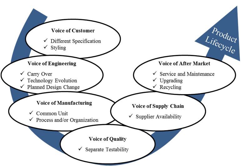
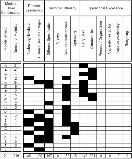
crowaves to motor vehicles.4 Modular Function Deployment 17 To sort this list by product types the North American Industry Classification System (NAICS) was used. Expectation was that all Module Function Deployment projects would be for companies classified within the manufacturing sector, however, only 90% of the projects were classified as manufacturing. Looking further, the remaining 10% of companies had a main business practice which lent itself to other NAICS codes but contained a branch dedicated to manufacturing. The distribution of products is shown in Fig. 4.7. In the following sections four demonstrations of Modular Function Deployment are taken from this database. Each case represents a unique situation that was il- lustrated using the unique application of Module Drivers to impart a business strategy to the product architecture. 4.4.1 Riding-Machine Platform The company in this demonstration has for over 50 years had a major focus on the Customer Intimacy Value Discipline with a minor interest in Operational Excel- lence. The demonstration of Modular Function Deployment for this company rep- resents a whole vehicle platform execution; over two hundred different Technical Solutions were addressed in the integration of 30 different product lines into a sin- gle product platform. The thirty different product lines were manufactured on no less than five different production lines in one factory and a minimum of two pro- duction lines in separate satellite factory. With the appearance of each new genera- tion of product, a new production line was established to support that product. Furthermore, as each new generation of product was introduced, the previous gen- eration of product was retained, including any related service and support systems. Many of the product variants were further customized after they left their respec- tive production line. There were two strategic objectives in applying modularity to a new product platform. The first was a technology strategy to reduce engineering effort within individual product lines by eliminating duplicate and competitive Technical Solu- tions that were used to fulfill the same Customer Value. The outcome expected was not just a reduction in engineering effort but also an increase in product con- figurability of product variants. The second was a manufacturing strategy to re- duce the number of different product lines by establishing a module system that embodied more Customer Value driving variance. Execution of Step 3 of Modular Function Deployment was performed in two it- erations with the first focused on imparting the project team member’s current perception of the business strategy to all the Technical Solutions considered for the product platform, the data of which is shown in Fig. 4.10 and then illustrated for evaluation in Fig. 4.8.
18                                                            Mark W. Lange and Andrea Imsdahl

Fig. 4.8 Initial distribution of unique Module Driver profiles across the Value Disciplines for the
technical solutions of a riding-machine platform.

Fig. 4.9 Final distribution of unique Module Driver profiles across the Value Disciplines for the
Modules of a riding-machine platform.
4 Modular Function Deployment                                                            19

Fig. 4.10 The Module Indication Matrix showing the initial scoring of Module Drivers for the
riding-machine platform Technical Solutions.
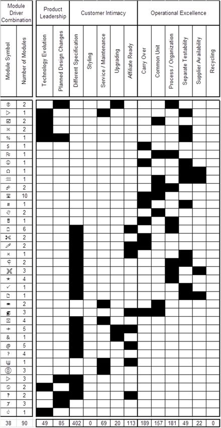
20                                                       Mark W. Lange and Andrea Imsdahl

Fig. 4.11 The Module Indication Matrix showing the initial scoring of Module Drivers for the
riding-machine platform Modules.
4 Modular Function Deployment                                                                   21

Fig. 4.12 Initial Module Driver profiles for building air conditioning system Technical Solutions.

   The second iteration was a review of the results of the first phase, with the add-
ed procedural requirement of reducing the number of applied Module Drivers to a
maximum of two per Technical Solution and then integrating functionally related
Technical Solutions into strategic modules, the data of which is shown in Fig. 4.11
and then illustrated for evaluation in Fig. 4.9. This requirement was driven by the
desired alignment of the product architecture to only two Value Disciplines; pri-
mary Customer Intimacy and secondary Operational Excellence.
   From the results of the first phase, of the 125 different Technical Solutions
considered for the product platform, over 100 were identified as belonging to two
or more value disciplines, in particular the intersection of Customer Intimacy and
Operational Excellence and secondarily with 39 of these Technical Solutions ac-
quiring a Module Driver profile that spanned over all three value disciplines.
   This effect of applying the Module Drivers is quite common and reflects the
fact that the team members have not negotiated the tactical means of imparting the
desired business strategy in a product platform. A resolution is reached by decom-
posing the Technical Solution into those parts that correspond best to a single val-
ue discipline or by aggregating the Technical Solution into a broader function to
emphasize the importance of a single value discipline.
   The platform resulted in 90 modules with roughly equal numbers on the OE
(21), OE+CI (27) and CI (23) value disciplines, which accounts for about 80% of
the module system of the product platform. This was a dramatic improvement in
understanding the needs of realizing the business strategy; product variance was
22                                                           Mark W. Lange and Andrea Imsdahl

Fig. 4.13 Initial Module Driver scoring for building air conditioning system Technical Solutions.

desired but there were still issues in the manufacturing of technology that need to
be resolved to improve the performance of the product platform.

4.4.2 Building Air Conditioning System

The products in the building air conditioning system (BACS) market compose a
landscape that has changed little over the last 75 years. Technology in the market
has remained consistent forcing competitors to find other way to differentiate
themselves from each other. As regions of the world are beginning to develop,
opportunities for market growth are also developing particularly in the Middle
East and Africa.
    The project demonstrated here was looking to capture a part of this growing
market. An additional challenge posed to the team was global regulations had led
to the ban of a domestically used refrigerant. To seize the market opportunity, the
BACS company needed to convert their existing product to the new refrigerant in
4 Modular Function Deployment 23 Fig. 4.14 Final distribution of unique Module Driver profiles across the Value Disciplines for the module system of the building air conditioning system. the shortest amount of time possible. To achieve this goal the platform was going to need to be focused on the value discipline of Operational Excellence. The first iteration of the platform identified 219 modules with 21 unique Mod- ule Driver profiles. 37% of the modules were located wholly in Operational Ex- cellence. 12% appeared in the overlap between Customer Intimacy and Opera- tional Excellence. 2% were entirely Customer Intimacy. 7% showed up as Product Leadership and Customer Intimacy. Another 2% was completely Product Leadership. The remaining 39% appeared at the intersection of all three value disciplines. To enable the program objective of launching the platform in a truncated lead time, the platform requires a strategy with an emphasis on Operational Excellence. With the initial distribution, there was a large disconnect between business strate- gy and team strategy. The initial distribution showed 37% of the modules were exclusively Operational Excellence. This was not a high enough percentage to at- tain the quick product launch requested by management. Management realigned the team and gave them the goal of 80% Operational Excellence. After the realignment of the team, a second iteration of the MIM was generat- ed. The result was 51 modules with 13 unique profiles. The new distribution had 71% Operational Excellence, 18% Customer Intimacy and Operational Excel- lence, 8% Product Leadership and Customer Intimacy, and 4% Product Leader- ship. The updated profiles were closer to the goals outlined by management.
24                                                         Mark W. Lange and Andrea Imsdahl

Fig. 4.15 Final Modular Indication Matrix for the Modules for the building air conditioning sys-
tem platform.

4.4.3 Construction Equipment Accessory

Modular Function Deployment is often applied to physical products that result in a
module system assembled using mechanical fastening systems. This demonstra-
tion shows a product module system that is assembled using welding processes.
   The company behind this demonstration has an established 20-year manufac-
turing strategy that includes outsourcing of the entire product, sub-systems or ac-
cessories to any available regional manufacturer. The availability of “strategic
suppliers” allows this company to compete with region-based third party providers
of the same accessory. Furthermore, there is a clearly stated marketing strategy of
not desiring to be perceived as a Product Leader on the market, instead they intend
on providing a total construction equipment solution that satisfies the needs any
customer that purchases equipment.
   The product platform is composed of 14 unique Module Driver profiles repre-
senting 21 different modules. The scoring is summarized in Fig. 4.16. The Module
Driver profiles are distributed in the Value Disciplines shown in Fig. 4.17.
   The Module Driver profile for the modules in this product platform illustrates a
strong desire by the client to deliver product variants from efficient manufacturing
4 Modular Function Deployment                                                             25

Fig. 4.16 The Module Indication Matrix showing the scoring of Module Drivers for the Modules
of the construction equipment accessory.

processes. 19 of the identified modules are positioned over the Value Discipline of
Customer Intimacy, yet 18 of these modules are located in the intersection of ei-
ther the Value Discipline of Operational Excellence (12 different modules) or
Product Leadership (6 different modules).
   In practice this strategy is difficult to implement. On one hand manufacturing
processes are best optimized when there is very little or no variance and on the
other hand variance is required to fulfill customer needs. The compromise is to es-
tablish regional manufacturing lines that are optimized for the range of variants
that are needed for a regional consumer.

4.4.4 Cell Phone

One of the earliest applications of Modular Function Deployment was on a mobile
phone, more commonly referred to as a cell phone. The client for this demonstra-
tion has a well-developed manufacturing strategy that promotes a highly automat-
ed cell-based manufacturing system intended to product large volumes of product
for delivery to a variety of different global markets. After the execution of Modu-
lar Function Deployment, 12 different strategic modules were established for the
product platform, which are shown in with their scoring from the Module Indica-
tion Matrix in Fig. 4.18.
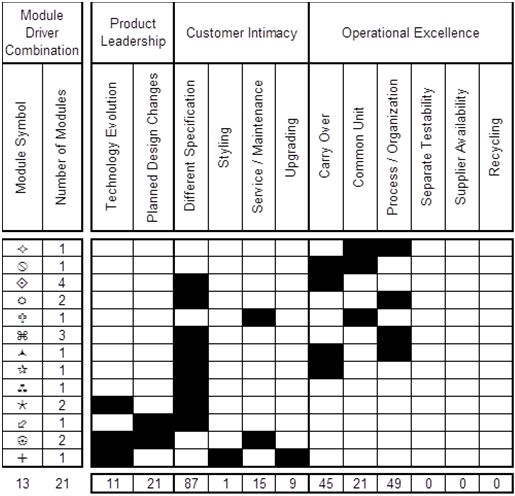
26                                                           Mark W. Lange and Andrea Imsdahl

Fig. 4.17 Distribution of unique Module Driver profiles across the Value Disciplines for the
module system of a construction equipment accessory.

Fig. 4.18 The Module Indication Matrix showing the scoring of Module Drivers for the Modules
of the cell phone.
4 Modular Function Deployment                                                                   27

Fig. 4.19: Distribution of unique Module Driver profiles across the Value Disciplines for the
module system of a cell phone.

   From the distribution of the unique Module Driver profiles shown in Fig. 4.19,
the product architecture clearly reflects the manufacturing strategy of the client.
Of the 12 modules identified for the platform, 10 of those modules are directly
aligned to the Operational Excellence Value Discipline.
   All of the Module Drivers, as defined, were utilized and produced eight unique
combinations for the 12 different Modules in the platform. Notice that nine of
these 10 modules have acquired the Common Unit Module Driver, indicating that
these Modules will be used in every product variant configured from the module
system. Notice also that four of this set of 12 Operational Excellence Modules is
contributing to the Product Leadership Value Discipline; Two Modules driven by
Planned Design Changes and two Modules driven by Technology Evolution.
   If one should emphasize the importance of responding to the strategy of provid-
ing product variance, notice that three of the 12 Modules are aligned with the Cus-
tomer Intimacy Value Discipline, where only one is clearly aligned with the Mod-
ule Drivers for Styling plus Upgrading. This is the Module intended to carry the
greatest variance in the platform. However there is also performance variance in-
dicated using the Different Specification Module Driver for the two remaining
Modules.
28                                                        Mark W. Lange and Andrea Imsdahl

4.5       Conclusions

Industrial companies are applying product architectures to realize business objec-
tives. In this chapter the concept of a business strategy represented as a Value Dis-
cipline has been integrated with Modular Function Deployment’s Module Drivers
to show where in a product platform that a project team has imparted the business
strategy. Using this approach during the execution of Modular Function Deploy-
ment, it has been possible for project teams to discern the strategic intent their de-
cisions have made in selection of Modules by reviewing the distribution over the
seven different Value Discipline spaces using the Module Driver profiles.
   Sometimes there are often a great number of tough decisions that need to be
made by project teams. Ensuring that the team remains focused on a primary and
secondary Value Disciplines requires careful review of the application of Module
Drivers and iterating on results in order to impart the desired business strategy.
This makes the application of Modular Function Deployment a unique approach to
the development of a modular product platform; it can be applied to devise mod-
ule based product architecture (the tactic) and it can be applied to explain the ob-
jective of the module based architecture (the strategic).

References

Baldwin CY, Clark KB (2000) Design Rules: Volume 1, The Power of Modularity. MIT Press,
   Cambridge, MA
Bowman D (2006) Effective product platform planning in the front end. In: Product Platform and
   Product Family Design; Methods and Applications, Springer Science + Business Media, New
   York, NY
Christopher A (1964) Notes on the synthesis of form. Harvard University Press, Cambridge, MA
Ericsson A, Erixon G (1999) Controlling Design Variants: Modular Product Platforms. Society
   of Manufacturing Engineers, Dearborn, MI
Erixon G (1998) Modular Function Deployment – A Method for Product Modularization. Doc-
   toral Thesis: The Royal Institute of Technology, Dept. of Manufacturing Systems, Stock-
   holm, Sweden
Hölttä KMM, Salonen MP (2003) Comparing three modularity methods. In: Proceedings of
   ASME Design Engineering Technical Conferences, Chicago IL, 2-6 Sept 2003
Hölttä-Otto K (2005) Modular Product Platform Design. Doctoral Thesis: Helsinki University of
   Technology, Machine Design, Espoo
Hölttä-Otto K and Otto K (2006) Platform concept evaluation. In: Product Platform and Product
   Family Design; Methods and Applications, Springer Science + Business Media, New York,
   NY
Marion TJ, Simpson TW (2006) Platform leveraging strategies and market segmentation. In:
   Product Platform and Product Family Design; Methods and Applications, Springer Science +
   Business Media, New York, NY
Nightingale DJ, Srinivasan J (2011) Beyond the lean Revolution: Achieving successful and sus-
   tainable enterprise transformation. American Management Association, New York, NY
Nilsson P (1998) The Chart of Modular Function Deployment, 4th Workshop on Product Struc-
   turing, Delft University of Technology, 22-23 October
4 Modular Function Deployment                                                                 29

Pimmler TU, Eppinger SD (1994) “Integration Analysis of Product Decompositions,” ASME
   Design Theory and Methodology Conference, Minneapolis, MN
Simpson TW, Siddique Z, Jiao RJ (2006) Product Platform and Product Family Design; Methods
   and Applications. Springer Science + Business Media, New York, NY
Stewart DV (1981) Systems Analysis and Management: Structure, Strategy, and Design, Petro-
   celli Books, New York
Treacy M, Wiersema F (1995) The Discipline of Market Leaders. Addison-Weasley Publishing,
   Reading, MA
Ulrich K T, Eppinger SD (2008) Product Design and Development. McGraw-Hill, New York,
   NY
Vos JAWM (2001) Module and System Design in Flexibility Automated Assembly. In: DUP
   Science, Netherlands, Chap. 2, pp. 23
Östgren B (1994) Modularisation of the product gives effects in the entire production. Licentiate
   Thesis: The Royal Institute of Technology, Dept. of Manufacturing Systems, Stockholm,
   Sweden
You can also read