MTU ASSEMBLY INSTRUCTIONS - Walk-in Awning & Drive-by Awning - The Awning Company
←
→
Page content transcription
If your browser does not render page correctly, please read the page content below
MTU ASSEMBLY
INSTRUCTIONS
Walk-in Awning & Drive-by Awning
CONTENTS
PAGE 4         SPECIFICATIONS

PAGE 5         AWNING POLE PLAN

               VEHICLE PARKING SET UP

PAGE 6         STEP 1

               WALK IN AWNING
PAGE 7         STEP 2

PAGE 7         STEP 3

PAGE 8         STEP 4

PAGE 8         STEP 5

PAGE 8         STEP 6

PAGE 9         STEP 7
PAGE 9         STEP 8

PAGE 9         STEP 9

PAGE 10        STEP 10
PAGE 10        STEP 11

PAGE 11        STEP 12

PAGE 11 - 12   STEP 13

PAGE 13        STEP 14

PAGE 14        STEP 15
PAGE 14        STEP 16

               MTU BALLAST BAG DEPLOYMENT

PAGE 15        STEP 1

PAGE 15        STEP 2

PAGE 16        STEP 3

PAGE 16        STEP 4

               MTU DEPLOYMENT OF WATER BALLAST

PAGE 17        STEP 1

PAGE 17        STEP 2
PAGE 18        STEP 3

PAGE 18        STEP 4

PAGE 19        DRIVE BY AWNING

PAGE 19        DISMANTLING

PAGE 19        SAFETY AND MAINTENANCE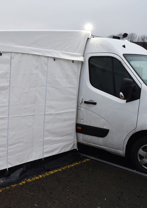
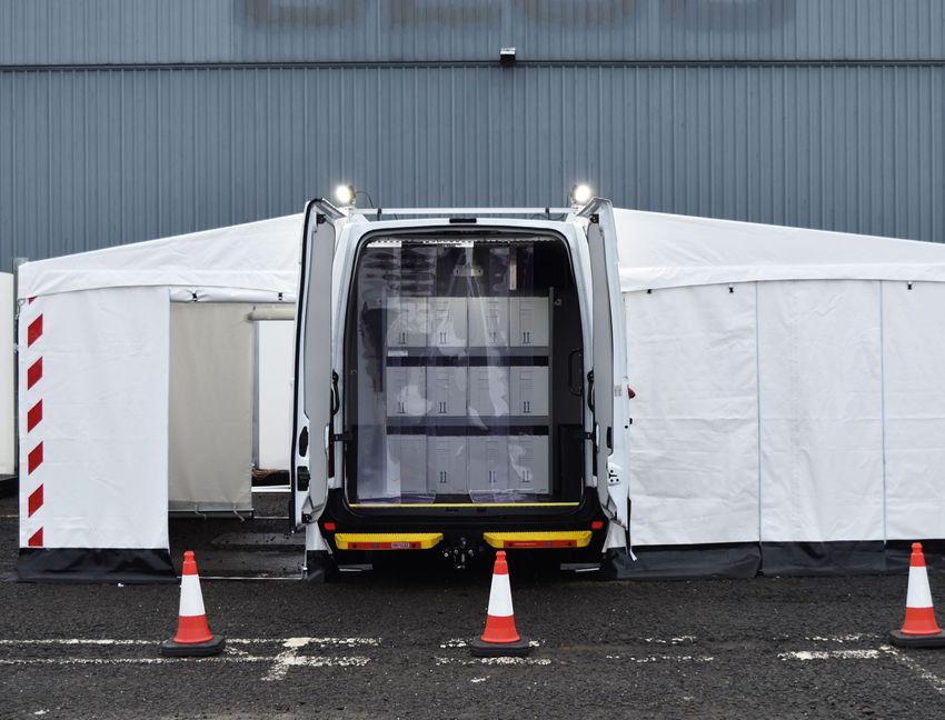
SPECIFICATIONS

Vehicle-Renault Master
3.5m OD
3.0m Projection
Includes two walk-in ‘customer’ cubicles with 2 roll up doors and
clear dividers to separate corridor. Clear dividers with iPad tablet
pockets, 2 mirror pockets and 2 flaps with PVC handles.

PAG E 4
AWNING POLE PLAN

                        PART    DESCRIPTION

                        1 O/S   Drive on Plate Front O/S
                        1 N/S   Drive on Plate Front N/S
                        2 O/S   Drive on Plate Rear O/S

                        2 N/S   Drive on Plate Rear N/S
                          3     Roof Rail LHS
                          4     Roof Rail RHS
                          5     Roof Rail Centre
                          6     Steel Knuckle LHS

                          7     Steel Knuckle RHS
                         8      Steel Knuckle Centre
     6 - LH Knuckle       9     Front Fascia Rails (Pair)
                         10     Corner Post LHS
                         11     Corner Post RHS
                         12     Corner Post Centre
                         13     Front Baseframe (Pair)
                         14     Side Baseframe (Pair)
                         15     Internal Divider Leg
                         16     Internal Divider Baseframe
                         17     Figure 8 Apex (Pair)
                        18A     Storm Bar
                        18B     Storm Bar
     7 - RH Knuckle      19     Purlin (Pair)
                         20     Roof Rail LHS
                         21     Roof Rail RHS
                         22     Front Fascia Rail
                         23     Steel Knuckle LHS

                         24     Steel Knuckle RHS
                         25     Corner Post LHS
                         26     Corner Post RHS

                         27     Front Baseframe
                         28     Side Baseframe (Pair)
                         29     Figure 8 Apex (Pair)

   8 - Centre Knuckle    WB     Weighted Base

                                                             PAG E 5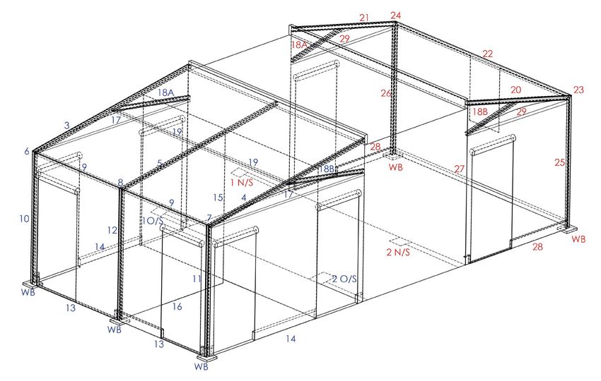
VEHICLE PARKING SET UP
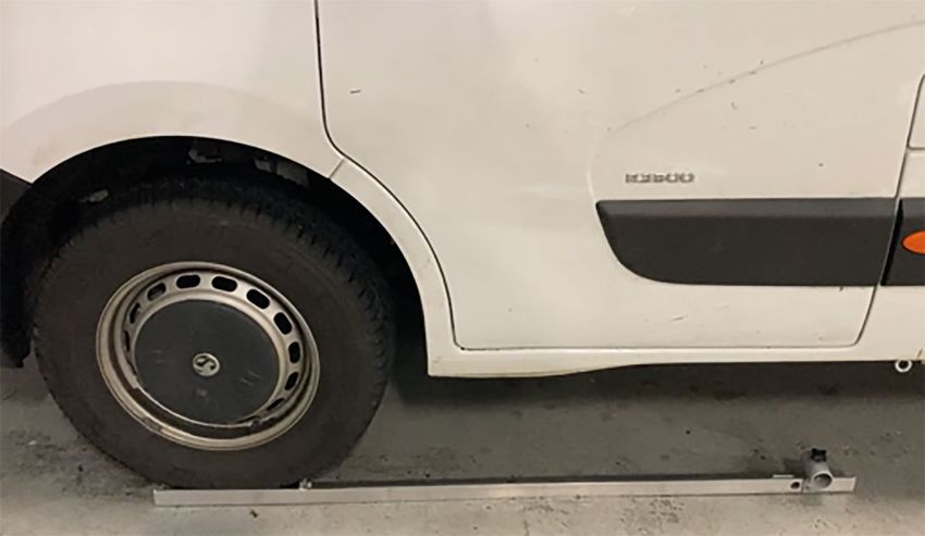
STEP 1
Reverse vehicle onto the wheel
anchor plates 1, 2, 3 & 4. Ensure
the plates are in line with the
wheels.
Correct position in line with vehicle
PAG E 6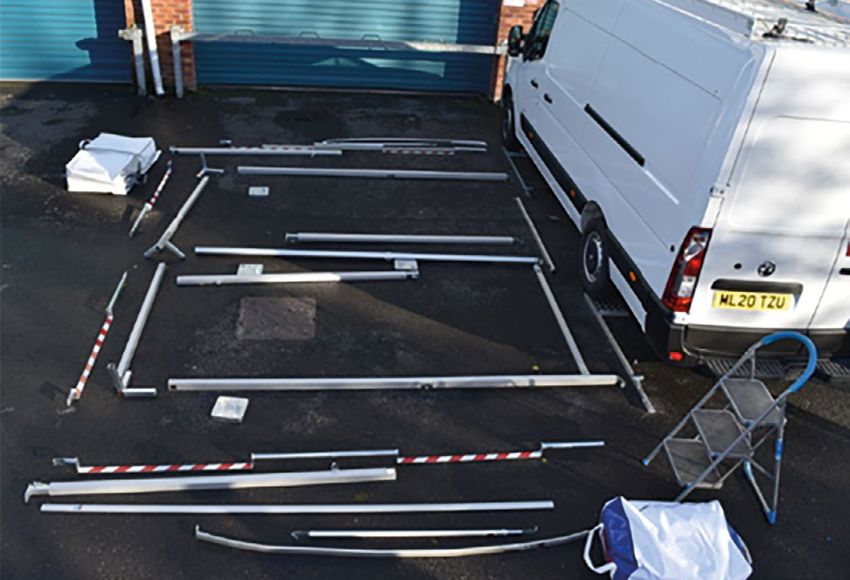
WALK IN AWNING
                                                    All poles labelled
                                                    blue, all sheeting
                                                    labelled blue.

STEP 2
Lay out all the awning poles so
everything is easy to hand. Ensure all
the numbered poles are laid out in
their correct position as illustrated in
Pole Plan.

                                   Left & Right

STEP 3
Place Roof Rails 3, 4 & 5 into
the Hook receivers. You will
notice Roof Rail 5 is not the
same orientation as 3 & 4.
This is normal.
                                           Centre

                                                                         PAG E 7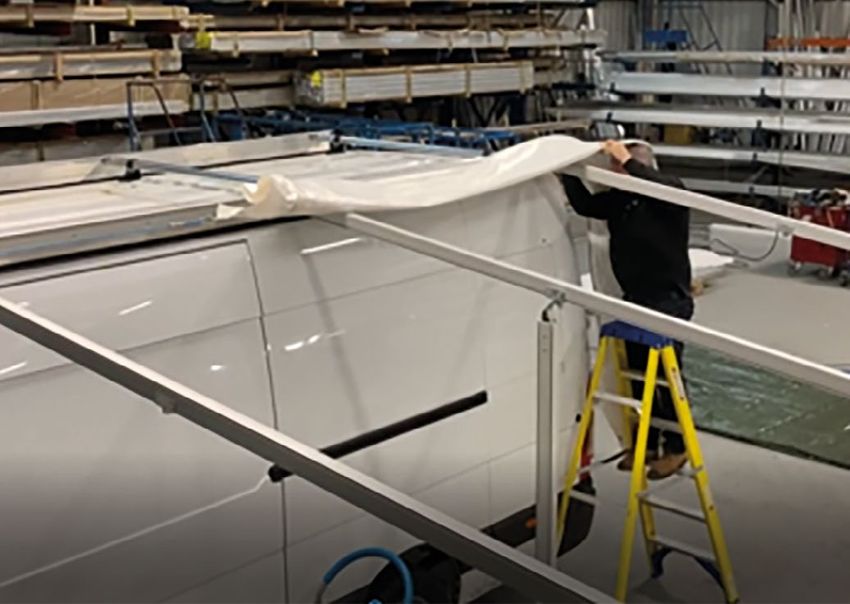
STEP 4
Align all aluminium beams with the steel knuckles, these are the three pictures labelled on page 5.
Assemble the Front Facia Rails 9 (Pair) into the steel knuckle brackets 6, 7 & 8. Steel knuckle 6 is left
hand and has to be assembled into the front Facia 9 with the routed part of the Facia Rail pointing
downward *Beware the steel knuckles are angled at the awning pitch.

STEP 5
Repeat the process on the centre knuckle 8 and right-hand knuckle 7. Ensure the steel knuckle spring
buttons all locate into the extensions.

STEP 6
Offer the front Facia assembly into the roof rails
3, 4 & 5. Note- if 3 people are assembling the
Awning this is the easiest option as all 3 roof rails
need to be simultaneously received into the steel
knuckles. If just 2 people are assembling, then
you will have to start at one end and work across
placing the centre knuckle next. If it snags, then it
is because the roof rails are not aligning with the
steel knuckles. Ensure all the spring buttons align
with the holes in the roof rails.

PAG E 8
STEP 7
(2-person assembly) Lift the assembled framework
up to head height (one person at each end) and fit
the corner posts 10 & 11 into the steel knuckles. *If
short of height you will need to use step ladders.
Once the two corner posts 10 & 11 are located you
can then locate the centre post 12 into the steel
knuckles. If 3 people are available this can all be
done in one process.

                                                        STEP 8
                                  Baseplate with hook
                                  Facing front

                                                        Locate the weighted base plates (WB) onto the
                                                        bottom of the corners posts 10 & 11 and centre post
                                                        12. Ensure the welded half eye ring is on the outside
                                                        edge of the structure, this is to locate the hook on
                                                        the ratchet straps later in the assembly process.

STEP 9
Assemble the remaining framework including all base
frame components 13,14,15. Ensure all base frame
tubes including door plates are positioned in the
correct place, see Pole plan for correct layout.

                                                                                                    PAG E 9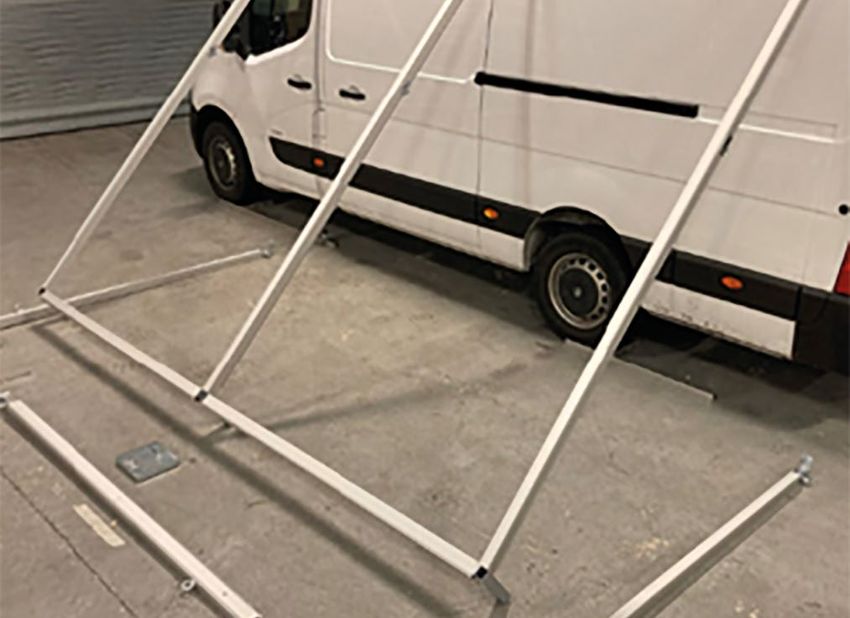
STEP 10
Locate the internal divider leg 15
into the receiver on the centre roof
rail 5. You will find this will only
locate one way.

STEP 11
Fit baseframe 16. Take a visual look at
the assembled framework and ensure
the corner posts are vertical.
DO NOT FIT THE STORM BARS UNTIL
THE WHOLE AWNING IS ASSEMBLED.
Once the base frame is located and
secured in place, then the awning
is ready for all PVC sheeting to be
attached.

PAG E 10
ATTACHING PVC SHEETING

STEP 12
Fit the pair of front sheets. Unzip
the front panels as this will aid in
the assembly process when feeding
the keder edge into the corner post
grooves.

STEP 13
Unroll the roof sheet so that the leading
keder edge is exposed to receive into the
keder rail on the roof. To aid assembly a
rope is supplied, this should be placed
over the top of the roof rails with the ‘rope
man’ at the cab end. Clip the carabiner
on to the roof sheet D ring. Whilst one
operative is feeding the roof keder into
the groove the 2nd operative ‘rope man’
should gently pull on the rope to ease the
roof sheet along.

                                                PAG E 1 1
Ensure the weight of the roof sheet is pushed over the roof rails so that the ‘rope man’ is not pulling against the sheet snagging on the framework. If you have a 3rd person, they can help tease over the excess weight of the roof sheet. A second rope can be attached to the front valance D Ring and this operative can gently pull the excess weight of the sheet over the roof rails. The apex sheet element of the roof sheet is held in place against the vehicle with built in magnets but secure the roof sheet temporarily in place using the ratchet on to the front valance D Rings. CAUTION - Rope Man - do not pull excessively if the roof sheet snags. Ensure the roof sheet is correctly aligned on the framework i.e., it is not pulling off to one side or the other. Ratchet straps have a hook on each end which locates on to the weighted basefoot and front valance D ring with large carbini hook. Please Note- do not clip this onto the Apex D ring at this stage as this will hinder fitting of the side sheets and Apex rail 17. PAG E 12
STEP 14
Slide the Apex Rail (Pair) 17 on to the
inside keder edge of the Apex sheets.

Then slide the end sheets into place.
You will notice one end is magnetic and
shaped to the side of the vehicle.

This is tensioned down to the drive on
anchor plates with a short ratchet strap.

Repeat the process on the rear end
sheet. Tension all the sheets down
using the cam buckle straps on the
inside of the awning.

                                            PAG E 1 3
STEP 15
Fitting the internal dividers- the two
dividers hang from the purlin brackets
on the roof rails.
Thread the aluminium tube through the pocket
on the PVC divider sheet. You will notice one end
of the purlin 19 is hooked and the other end is at
right angles. The hooked end locates on to roof
rails 3 & 4 and the right angle on to roof rail 5.
Unzip so as to aid easy assembly into the keder
groove on the internal divider leg 15 and then
Velcro on to the inside face of the end sheets.
Fit the cubicle divider sheet by feeding the keder
edge into the underside of roof rail 5. Start at the
lower end by the centre post 12 and push up the
higher end. Unzip the sheets to feed vertical keder
edges into centre post 12 and internal divider leg 15.
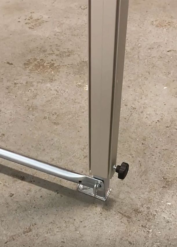
STEP 16
Ensure all sheeting is tensioned down to the base frame tubes.
Then finally fit the pair of storm bars 18a & 18b to the vehicle
side using the M8 handwheel.
Finally do a visual check of the awning structure and assess
the weather forecast conditions for the duration of the MTU
deployment.
PAGE 14MTU BALLAST BAG
DEPLOYMENT
STEP 1
Position ballast sling on floor.
STEP 2
Place one pre-cutted sandbag
approx. 25-30kg (Dependent on
material used) on the centre of the
PVC sandbag sling.
PAG E 1 5STEP 3 List all 4 corners up to one point and thread the 2.5m strap through the 4 loops. STEP 4 Thread one end of the strap through the eye ring on the corner post and tension. Adding more ballast weight – undo the ballast sling and place a 2nd, 3rd or 4th sandbag into the sling. Max weight with 4 sandbags is approx. 100kg. PAGE 16
MTU DEPLOYMENT OF
  WATER BALLAST
Study the ‘Wind Management’ /
                                                           Water Source
‘Ballast table’ and decide on the                          • Standpipe/Hose Pipe
suitable ballast weight required
                                                           • Water Ballast Tank
to secure the awning.
                                                           • 25L Plastic Refillable Drum

STEP 1
Filling a 25kg PVC Water Ballast:
After deciding on the method of filling, place the PVC Water
ballast bladder at the base of each of the corner posts. You
can partially fill the bladder at the source of the water or fill
it in situ. CAUTION: The maximum permissible weight one
person should lift is 25kg but consult your risk assessment
and Health & Safety manual for further guidance.

                                                  STEP 2
                                                  If only 25kg, one person can lift the bladder into
                                                  place manually. If you have the use of a trolley,
                                                  this can be used to partially or fully filled
                                                  bladder into position.

                                                                                                       PAG E 1 7
ALL CORNER POSTS HAVE TO HAVE BALLAST,
as per the ‘Wind Management’ / ‘Ballast Table’
STEP 3
Using the 2.5m cam buckle strap,
threaded one end through loops
on the 25kg bag or eyelet on the
50kg ballast bag.
STEP 4
Thread the strap through the
eye ring on the corner post and
tension. Tidy up excess strapping
by wrapping it around the strap.
PAGE 18DRIVE BY AWNING
All poles labelled
red, all sheeting
labelled red.
DISMANTLING
This process is the reverse of the assembly.
SAFETY AND MAINTENANCE
Risk Assessment & Monitoring Wind Management
It is essential that for every site a risk Appropriate ballast is supplied with water tanks
assessment is carried out to ensure the safety or sandbag slings, these ratchet to the legs on the
of the structures in high winds. This should M10 eyebolt as pictured. Refer to Ballast tables for
include exposure of the site to prevailing recommended weights v windspeed.
winds. Forecasts and wind speeds should be
monitored, and plans should be in place to deal
with extreme conditions.
In high winds it necessary to close all walls.
This will stop pressure from building up in the
awning during adverse conditions. Where the
possibility of strong winds exists, extra ballast
should be added as necessary to ensure the
structure is firmly secured. Refer to ballast
tables.
If faced with the prospect of very extreme
weather conditions the awning should be
dismantled. If this is not possible, removal of
the PVC roof and gable panels will significantly
reduce any imposed loads on the frame. If
conditions are so extreme that it is not possible
Periodic Inspections
to remove the PVC sheeting, then they can be A competent person should carry out
cut out with a sharp bladed knife. This may periodic inspections. These inspections are
release sheets to be blown downwind but is to ensure the components are not unduly
preferable to allowing the framework to fail as worn and that there is no damage to the
this would cause considerably more damage. structure or to the PVC sheeting.
PAG E 1 9For further instructions and advice
contact our friendly team, or
scan the QR code to watch our
instructional video.
The Awning Company UK Limited
Unit 1, Jubilee Works, Vale Street
Bolton BL2 6QF
Tel: +44 (0)1204 544900
Fax: +44 (0)1204 544901
sales@theawningcompany.co.uk
www.theawningcompany.co.ukYou can also read