N550 Wood-Fire Oven Installation Instruction Manual - Glen Dimplex Americas
←
→
Page content transcription
If your browser does not render page correctly, please read the page content below
N550 Wood-Fire Oven
                           Installation Instruction Manual

CERTIFIED for USA & CANADA | SAFETY TESTED to UL 1482-2011 & ULC-S627-2000

CAUTION!
Please read this entire manual before you install or use your new oven. Failure to
follow instructions may result in property damage, bodily injury, or even death. Improper
installation could void your warranty!

SAFETY NOTICE:
If this oven is not properly installed, a house fire may result. For your safety, follow the
installation instructions. Never use make-shift compromises during the installation of this
oven. Contact local building or fire officials about permits, restrictions, and installation
requirements in your area.

                                                                             7215040100R01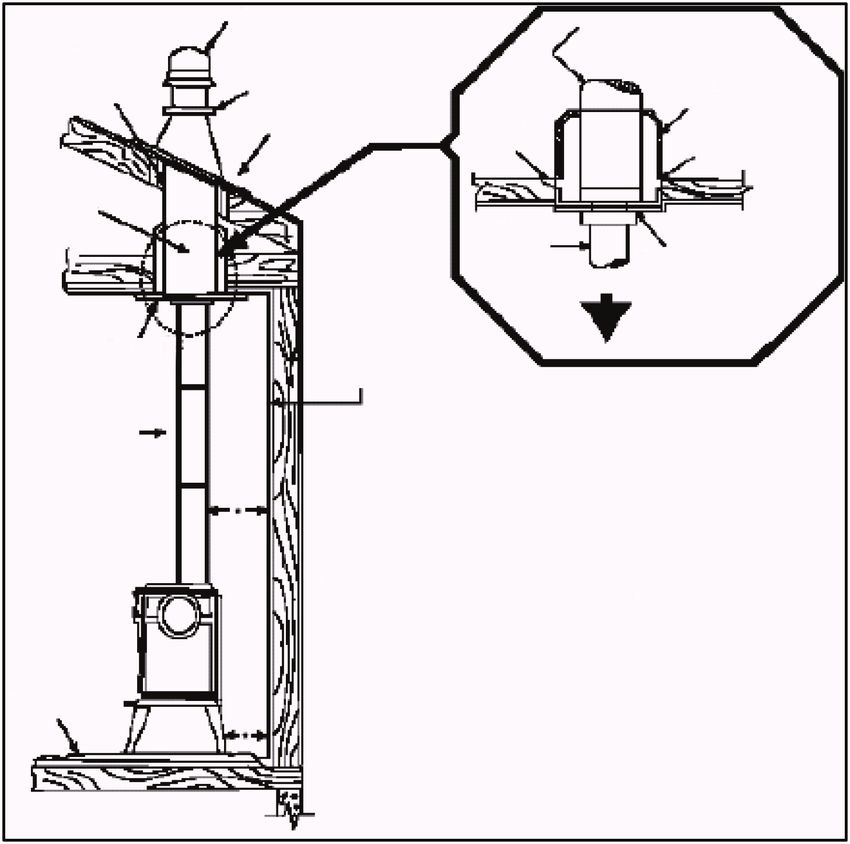
Table of Contents

          Welcome & Congratulations . . . . . . . . . . . . . . . . . . 3
          CAUTIONS & WARNINGS . . . . . . . . . . . . . . . . . . 4
          Installation . . . . . . . . . . . . . . . . . . . . . . . . . . . . . . . . 6
          Operating Instructions. . . . . . . . . . . . . . . . . . . . . . 16

          Warranty . . . . . . . . . . . . . . . . . . . . . . . . . . . . . . . . 20

          Technical Support . . . . . . . . . . . . . . . . . . . . . . . . . 21

This manual covers installation and maintenance. Read carefully
before attempting to install, operate, or service the Wood-Fire Oven.

    ! 	NOTE: Procedures and techniques that are considered important
       enough to emphasize.
     	CAUTION: Procedures and techniques which, if not carefully
       followed, will result in damage to the equipment.
      WARNING: Procedures and techniques which, if not carefully
       followed, will expose the user to the risk of fire, serious injury, or
       death.

2                                                            www.nectre.com/usa-nectre
Welcome & Congratulations
Congratulations on the purchase of your Nectre Wood-Fire Oven! By
cooking with wood you’re helping to conserve energy.
Wood is an important renewable energy resource. Please do your part
to preserve our wood supply. Plant at least one tree each year. Future
generations will thank you.
Please carefully read and save these instructions.
CAUTION: Read all instructions and warnings carefully before
starting installation. Failure to follow these instructions may result in a
possible fire hazard or serious injury and will void the warranty.
Please record your model and serial numbers below for future
reference: model and serial numbers can be found on the Model and
Serial Number Label of your wood-fire oven.
NO NEED TO RETURN TO THE STORE
Questions with operation or assembly? Require Parts Information?
Product Under Manufacturer’s Warranty?
Contact us at: www.dimplex.com/customer_support
For Troubleshooting and Technical Support
OR Toll-Free 1-888-346-7539
Please have your model number and
product serial number ready. (See above)
3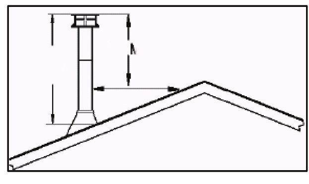
CAUTIONS & WARNINGS
For use with solid wood fuel               can cause smoke spillage
only – preferable dry, seasoned            and flames to come out of the
cord wood.                                 oven and create dangerous
①H
  ot while in operation. Keep             and possibly life threatening
    children, clothing and furniture       situations.
    away. Contact may cause skin         ⑧N
                                           ormal operation of the
    burns.                                 oven will result in momentary
② Do not install in a mobile home.         emissions of smoke into the
                                           room when the refueling door
③D
  o not burn garbage or                   is opened and closed. It is
    flammable chemicals or fluids          always recommended to install
    such as gasoline, gasoline-            strategically placed smoke
    type lantern fuel, kerosene,           detectors away from the oven
    charcoal lighter fluid, naphtha,       and to have a fire extinguisher
    engine oil, or similar liquids to      in a convenient location. Make
    start or ‘freshen up’ a fire in        sure that they are not influenced
    this oven. Some of these fuels         by small and normal wisps of
    can generate deadly carbon             smoke that can come out of the
    monoxides. Keep all such liquids       oven at the ignition or refueling
    well away from the oven while it       but close enough to provide
    is in used.                            safety.
④D
  o not connect to any air              ⑨N
                                           ever over fire your oven. If any
    distribution or duct system.           part of the oven starts to glow
⑤D
  o not elevate the fire by use of        red, over firing is happening. To
    a log cradle or grates. Build fire     correct over firing adjust the air
    directly on a 1 inch layer of ash      intake control to a lower setting.
    spread evenly over the base of       ⑩N
                                           ever put wood above the
    the firebox.                           firebrick lining of the firebox.
⑥D
  o not store fuel underneath
    the oven, within the specified
    installation clearance areas, or
    within the space required for
    charging and ash removal.
⑦A
  lways close the door after the
    ignition. Leaving door open

4                                                    www.nectre.com/usa-nectre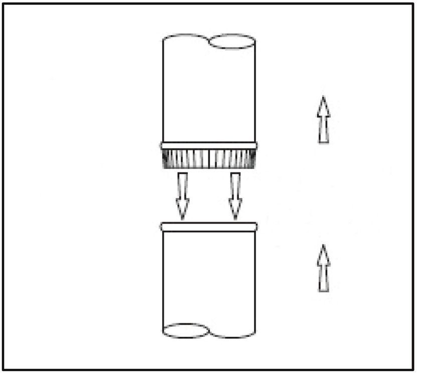
CAUTIONS & WARNINGS

                              501
                              BB00651          Manufactured by;
                                               Glen Dimplex New Zealand
                  Nectre N550 Wood-Fire Oven
                                               38 Harris Road, East Tamaki
                                               Auckland 2013, New Zealand

U.S
(in inches)

                          CAUTION
                        DO NOT OPEN
              NO USER-SERVICEABLE PARTS INSIDE

SAVE THESE INSTRUCTIONS
                                                                             5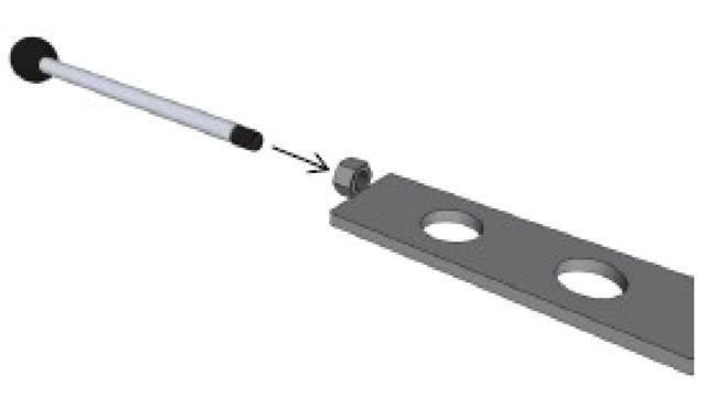
Installation

Before Installation                     2. The position of the handle should
                                            be at approximately 11 o’clock
After unpacking, check that the
                                            when the damper is open, and
following parts are included inside
                                            1 o’clock when the damper is
the wood-fire oven.
                                            closed.
• 2 side baffles
• Handle for air control                  ! NOTE: Do not alter the damper
• Lifter for cook plates                adjustment range to increase firing
• Allen key for adjustment              for any reason.
    of top air discharge
Assembling your Nectre
                                        Installing fire bricks
Wood-Fire Oven                          The oven comes with 4 fire bricks
                                        9" x 4½" x 1½" (230 mm x 115
The Nectre N550 Wood-Fire Oven          mm x 38 mm), a 19" (480 mm)
comes mostly assembled, however         long brick retainer as well as two
some parts may need adjusting /         triangular bricks 2" x 2 ¾" x 10"
to be added before firing the oven.     (50 mm x 70 mm x 250 mm) for the
It is important that the following      front. Refer to Figure 1.
components are used ensure
compliance.                             Place the four fire bricks upright, up
                                        against the rear wall of the firebox.
Installing the by-pass                  Place the U-shaped brick retainer
damper                                  over the top of the bricks such that
                                        the bricks fit inside the U-section.
1. Before installing the flue, the     This will hold them in place. Place
    by-pass damper handle must          the triangular firebricks at the front
    be fitted. The handle is supplied   of the firebox beneath the door
    inside the firebox. Insert the      opening.
    threaded end of the handle into
    the 10 mm (0.40”) hole on left
    side of the oven.                   Figure 1
                                                                      Brick retainer
	Looking down through the flue            Firebox side
                                           shield
  spigot locate the threaded end of
  the handle with the extended nut                                                         Rear
                                                                                       firebrick
  attached to the by-pass damper.
  Screw the handle all the way into
  the nut until tight.

                                               Triangular
                                                 firebrick

6                                                            www.nectre.com/usa-nectre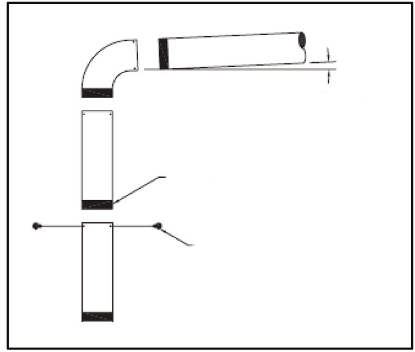
Installation

 ! NOTE: The firebricks may                 Installing top air control rod
already be in place upon arrival of         A stainless-steel rod with a thread at
your wood-fire oven.                        one end and black knob on the other
  ! NOTE: The triangular fire bricks        will have been supplied in the oven.
are siliconed in place for transit. After   Pass the threaded end of the rod
initial use the silicon will break down     through the hole near the top front
and they bricks can be removed.             corner on the left side of the oven.
Remove the side baffles by lifting          Push the rod through until one can
upand away from the wall prior to           feel it has located the nut on the air
removing triangular bricks                  slide, then screw rod until tight. Refer
                                            to figure 2. Check that the rod slides
                                            freely back and forth.
Installing baffle plate
1. T
    he oven comes with a 10" x
   12 ¾" x 6" (250 mm(d) x 325
                                            Figure 2 Top air control rod installation
   mm(w) x 150 mm(h) mm) baffle
   plate. This rests on the two lugs
   welded to the inside front of the
   firebox and on the brick retainer at
   the back of the oven.
2. P
    osition the baffle plate vertically
   towards the rear of the firebox
   with the 4" (100 mm) strip welded
   to the baffle at the top facing
   forward. Bring the top edge
   towards the front of the oven so
   that it slides up and over the two
   support lugs with the 4" (100 mm)
   strip located between them. Raise
   the lower rear edge of the baffle
   plate to rest on top of the brick
   retainer.
3. W
    ith the baffle plate in its correct
   position, ensure it is pushed all
   the way back so that it doesn’t fall.

                                                                                        7
Installation
Installing the floor protector material, you will need to convert
these to the R-value.
The oven must be placed on a
non-combustible floor protector with The following equations can be
an R-value of 2.12 or greater. For used to convert these factors to the
multiple layers, add R-values of R-value:
each layer to determine the overall • k-factor, is given with a required
R-value. When manufacturers thickness (T) in inches: R=1/k x T
provide a k-factor or C-factor for the
• C-factor, is given:
Figure 2 - R=1/C EXAMPLE:
If the floor protector is 4" brick with a C-factor of 1.25, over 1/2" mineral
board with a “k” factor of 0.29, the total R-value of the system (Rtotal) is:
4" brick C = 1.25 Rbrick = 1/1.25 = 0.8
1/2" mineral board K = 0.29, Rmineral = 1/0.29 x 0.5 = 1.724
Rtotal = Rbrick + Rmineral Rtotal = 0.8 + 1.724 = 2.524
In this example, the R-value is greater than 2.12 required and therefore this
floor protector is a suitable combination that provides the required thermal
protection.
In the USA, the floor protector must extend 8" (203 mm) beyond each side
of the flue loading door and 16" (406 mm) to the front. In Canada, the floor
protector must extend 8" (203 mm) beyond each side and the back of the
appliance and 18" (457 mm) to the front. Refer to figure 3.
Figure 3 Non-combustible floor protector requirements
8" (200mm) - Canada
In a rear vent
installation, the floor
8" (200mm) - 8" (200mm) - protection must also
OVEN
Canada TOP Canada extend under the
DOOR stove pipe/chimney
8" (200mm) 8" (200mm)
connector and a
USA - USA minimum of 2"
18" (457mm) - Canada
16" (406mm) USA (51 mm) beyond
each side.
8 www.nectre.com/usa-nectreInstallation
Positioning your not responsible for the product, if
wood-fire oven it is not installed following these
recommendations. The following
STANDARD INSTALLATION clearances may only be reduced by
CLEARANCES means approved by the regulatory
One of the main necessary authority.
precautions when installing a wood- A combustible surface is anything
fire oven is to leave sufficient space that can burn (i.e. sheet rock, wall
between the oven (top, sides, back, paper, wood, fabrics etc.) These
front, and under stove pipes) and surfaces are not limited to those that
any other material that can catch fire. are visible and include materials
It is extremely important that that are behind non- combustible
you respect required installation materials. If you are not sure of the
distances and that you respect local combustible nature of a material,
installation regulations. This is for consult your local fire officials.
your safety! The manufacturer is
Figure 4 a) Parallel installation b) Corner installation
A D C 45°
B
E
F
Table 1 Clearances to combustible surfaces
Description Dimension (in) Dimension (mm)
A – Back Wall to Flue Pipe 12.5" 318 mm
B – Side Wall to Flue Pipe 22.5" 572 mm
C – Wall to Flue Pipe 15" 381 mm
D – Back Wall to Appliance 10" 254 mm
E – Side Wall to Appliance 12" 305 mm
F – Wall to Appliance 5" 127 mm
– Ceiling to Appliance Top 51" 1296 mm
9Installation
Chimney connection
The chimney connector is a single walled pipe used to connect the oven to
the chimney. For use with the N550 Wood-Fire Oven the chimney connector
MUST be 6" (152 mm) in diameter, with a minimum thickness of 24-gauge
black steel or 26-gauge blued steel. The chimney connector must be suitable
for solid fuel, in good condition, and kept clean.
Aluminum or galvanized steel pipe is not acceptable for use with the
N550 Wood-Fire Oven. These materials cannot withstand the extreme
temperatures of a wood fire and can give off toxic fumes when fired.
! NOTE: Do not use the connector pipe as a chimney.
Table 5 a) Chimney connection b) Flue pipe attachment
1/4" slope per foot
Install crimped Flow Direction
Male Part Downwards
end towards of
oven Flue Gases
3 screws
Each chimney connector or flue pipe section must be installed to the oven
flue collar and to each other with the male (crimped) end toward the oven,
as per Figure 5A. Attach each of the sections to one another with three
equidistant metal screws, as per Figure 5B.
10 www.nectre.com/usa-nectreInstallation
This prevents any amount of Chimney requirements
condensed or liquid creosote from WARNING: Do not connect
running down the outside of the pipe
this wood-fire oven to a chimney
or the oven top. All joints, including
flue serving another appliance.
the flue collar connection must be
secured with three sheet metal WARNING: Do not connect to
screws to ensure that the sections any air distribution or duct system.
do not separate.
This oven must be connected to a
For the best performance, the 6" (152 mm) factory built UL 103 HT
chimney connector should be as chimney (ULC S629, in Canada) or
short and direct as possible, with a code - approved masonry chimney
no more than two 90° elbows. with a flue liner.
The maximum horizontal run is
An effective vapor barrier at the
36" (915 mm) and a recommended
location where the chimney or
total length of flue pipe should not
component penetrates to the exterior
exceed 10' (3.0 m). Always slope
of the structure must be maintained
horizontal runs upward ¼" per foot
as per the installer’s complying
toward the chimney.
method.
No part of the chimney connector
may pass through an attic, roof
space, closet, other concealed
space or through a floor or ceiling. All
sections of the chimney connectors
must be accessible for cleaning.
Where passage through a wall or
partition of combustible construction
is desired, the installation must
conform to NFPA 211 or CAN/
CSA-B365, and is also addressed in
this manual.
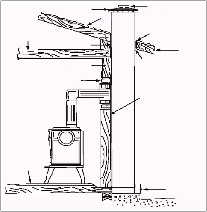
11Installation
Factory Built Chimney
When a metal prefabricated chimney is used, the manufacturer’s installation
instructions must be followed. You must also purchase (from the same
manufacturer) and install the ceiling support package or wall pass-through
and “T” section package, firestops (where needed), insulation shield, roof
flashing, chimney cap, etc. Maintain proper clearance to the structure as
recommended by the manufacturer. The chimney must be the required
height above the roof or other obstructions for safety and proper draft
operation. See below for chimney termination requirements.
Figure 6 Factory built chimney requirements
Listed Cap Listed Chimney
Maintain 1"
Clearance Attic Insulation
Storm Collar Combustible Shield
Flashing Ceiling
Specified
Joists
Clearance
Listed Chimney
Chimney Ceiling
Connector Support
To Oven
Ceiling Support Combustible
wall
Chimney
*Refer to
Clearances to
Floor
Protector Combustibles
12 www.nectre.com/usa-nectreInstallation
Masonry Chimney & Fireplace
When a metal prefabricated chimney is used, the oven may also be
connected to a masonry chimney, provided the chimney complies with the
construction rules found in the building code enforced locally. To ensure
that a masonry chimney meets the minimum standards of the National Fire
Protection Association (NFPA) it should be inspected by a professional to
make sure there are no cracks, loose mortar or other signs of deterioration
and blockage. Also have the chimney cleaned before the oven is installed
and operated.
Figure 7 Masonry chimney requirements
Concrete cap Fireclay flue
Rafter liner with
airspace
Ceiling joist Flashing
Eave
Combustible wall Clearance
18" minimum
Thimble -
12" of brick
Sheathing
Floor
protection
Airtight
clean
door
13Installation
When connecting the oven through Chimney Height
a combustible wall to a masonry
A masonry chimney or a listed
chimney, special methods are
factory-build chimney must be the
needed. Refer to figure 7. The
required height above the roof and
chimney must have either a clay liner
any other nearby obstructions. The
or a suitably listed stainless steel
chimney must be at least 3' (914
liner. If the masonry chimney has
mm) higher than the highest point
a square or rectangular liner that is
where it passes through the roof and
larger in cross sectional area than a
at least 2' (610 mm) higher than the
round 6" (152 mm) flue, it should be
highest part of the roof or structure
relined with a suitably listed
that is within 10’ (3050 mm) of the
6" (152 mm) stainless steel liner.
chimney, measured horizontally.
Do not downsize the flue to less
Refer to Figure 8.
than 6" (152 mm) unless the venting
system is straight and exceeds
25ft (7.6 m) in height. When passing
through a combustible wall, the Figure 8 Chimney height requirements
use of an insulated listed thimble is 2-10-3 RULE
required.
2' Min.
There are listed kits available to 3' Min.
Ridge
connect an oven to a masonry
10'
fireplace. The kit is an adapter
that is installed at the location of
the fireplace damper. The existing
damper may have to be removed to
allow installation.
14 www.nectre.com/usa-nectreC.
Si
Adj
F
D.
E ..
Installation F ..
Oven Dimensions
Figure 9 Dimensions for installer
27-1/4" 2"
22-1/4"
Back wall (5.1 cm)
(69.0 cm) Adjacent wall
(56.4 cm) installation
Residential
wall
A D Residential installation
C
45
o for Standard Clearance’s 5-1/2" (13
for Standard Clearance’s N350 N550
Adjacent wall
o
45 A .. 10.5" (26.7 cm) 12.5" (31.75 cm)
N350 N550 B .. 18" (45.7 cm) 22.5" (57.1 cm)
A .. 10.5"
F (26.7 cm) 12.5" C .. 15"
(31.75 (38.1
cm) cm) 15" (38.1 cm)
D .. 8" (20.3 cm) 10" (25.4 cm)
B .. 18" (45.7 cm) 32-5/8"
22.5" E(57.1
.. 10"cm)(25.4 cm) 12"33" (30.5 cm)
C .. 15" (38.1 cm)(82.8 cm) 15" F(38.1
.. 6.5"cm)(16.5 cm) 5" cm)
(83.8 (12.7 cm)
D .. 8" (20.3 cm) 10" (25.4 cm)
E .. 10" (25.4 cm) 12" (30.5 cm)
F .. 6.5" (16.5 cm) 5" (12.7 cm) Interna
27-1/4" 2" 13-5/8" Firebox
22-1/4"
(69.0 cm) (5.1 cm)
(56.4 cm)
(34.5 cm)
18.7" (4
26-5/8" 19-3/4" 1.5"
(67.5 cm)
5-1/2" (13.7 cm)
50.0 cm) 3.6 cm) 11.4" (2
11.8" (3
13-5/8"
32-5/8"
(34.5 cm) 33"
(82.8 cm) (83.8 cm)
5-1/2" (13.7 cm)
Internal Dimensions
Firebox Oven 5-1/2" (14
18.7" (47.5 cm) 19" (48.3 cm)
26-5/8" 19-3/4" 1.5"
(67.5 cm) 50.0 cm) 3.6 cm) 11.4" (29.0 cm) 12.6" (32.0 cm)
33" 11.8" (30.0 cm) 10" (25.4 cm)
(83.8 cm)
34"
(86.3 cm)
Internal Dimensions 11"
(27.9 cm)
15
Firebox Oven 5-1/2" (14.0 cm)
Interna
18.7" (47.5 cm) 19" (48.3 cm)
FireboxOperating Instructions
Cooking ! NOTE: The temperature
1. The Nectre Wood-Fire Oven gauge on the oven door is only
has the firebox at the top and a guide to the temperature in the
the oven below. Heat is directed oven. We have found that when
around the oven by closing the the gauge is reading 100° Celsius
damper located next to the flue (212° Fahrenheit), the internal
outlet. oven temperature is more like
180° Celsius (356° Fahrenheit). It
2. Before lighting your Nectre
is always recommended to use a
Wood-Fire Oven ensure that
meat thermometer when cooking.
the damper control is properly
located so that it closes and 4. To add more fuel to the fire, it is
swings open. The damper is advisable to open the damper
open when the control lever is in before opening the door. When
the down position and closed in the firebox is loaded, close the
the up position. Also ensure that door and then close the damper.
the steel inspection panel in the This will help prevent smoke from
bottom of the oven is in place entering the living space.
(not to be confused with the oven 5. For cooking, always have a brisk
tray). fire using small pieces of wood
3. To light your cooker, first make that provide plenty of flames.
sure that the damper is open This type of fire will maintain the
and the air spindle control (the oven temperature. For longer
spindle control is opened and burn time, larger pieces of wood
closed to control the rate of can be used and the spindle
burn) on the firebox door is also control closed off. The oven
open to its full extent. Light a fire temperature will drop when in
using finely chopped wood and this mode of operation.
establish it so that it has plenty 6. Your Wood-Fire Oven come with
of flames. As soon as the fire is two removable rings for stove top
going briskly, close the damper. cooking. Remove the rings to use
This directs the flames and the as a burner to cook additional
flue gases down the sides and foods in woks or pots suitable
around the oven. Keep the fire for wood burning applications
burning briskly until the oven is (contact your dealer for more
up to temperature. information).
16 www.nectre.com/usa-nectreOperating Instructions
Fueling Ventilation Suggestions
LOADING SUGGESTIONS It is important to note that wood
1. Once you have obtained a good combustion consumes ambient
bed of embers, you should oxygen in the room. In the case of
reload the unit. In order to do so, negative pressure, it is a good idea
open the air controls to maximum to allow fresh air in the room, either
a few seconds prior to opening by opening a window slightly or by
the oven’s door. Then proceed installing a fresh air intake system
by opening the door very slowly; on an outside wall.
open it one or two inches WARNING: do not alter the
(25-50 mm) for 5 to 10 seconds, damper adjustment range to
before opening it completely increase firing for any reason.
to increase the draft and thus
eliminate the smoke which
is stagnant in a state of slow Maintenance
combustion in the firebox. Then DISPOSAL OF ASHES
bring the red embers to the front Ashes should be removed from
of the firebox and reload the unit. the firebox every few days or when
Be careful when operating the ashes get to 2 to 3 inches deep.
Nectre Wood-Fire Oven with the Always empty the firebox when it
door open as coal or ash may is cold. Ashes should be placed
escape the firebox. in a metal container with a tight-
2. For optimal operation of your fitting lid. The closed container
wood-Fire oven we recommend of ashes should be placed on a
you to operate it with a wood noncombustible floor on the ground,
load approximately equivalent well away from all combustible
to the height of fire bricks. Avoid materials, pending final disposal.
wood from coming in contact with If the ashes are disposed of by
glass. Also avoid over firing the burial in soil or otherwise locally
oven and burning volatile fuels dispersed, they should be retained
as this is unsafe and will void in the closed container until a
warranty. cinders have thoroughly cooled.
17Operating Instructions
CREOSOTE – FORMATION & removed to reduce the risk of a
NEED FOR REMOVAL chimney fire.
1. When wood is burned slowly, it The sides of the oven will also
produces tar and other organic need to be inspected and
vapors, which combine with potentially cleaned every two
expelled moisture to form months. To achieve this the
creosote. The creosote vapors cooktop hotplates need to be
condense in the relatively cool removed so that the sides of the
chimney flue of a slow- burning oven can be scraped. The bottom
fire. As a result, creosote residue plate of the oven will then need to
accumulates on the flue lining. be removed in order to collect the
When ignited this makes an loose creosote.
extremely hot fire.
2. To prevent creosote build-up: Inspection & Cleaning
• Always burn dry wood. This 1. It is important to establish a
allows clean burns and routine for the fuel, wood burner
higher chimney temperatures, and firing technique. Check
therefore less creosote deposit daily for creosote buildup. Be
aware that the hotter the fire
•L eave the air control fully open the less creosote is deposited,
for about 5 minutes every time and weekly cleaning may be
you reload the oven to bring necessary in mild weather even
it back to proper operating though monthly cleaning may be
temperatures. The secondary enough in the coldest months.
combustion can only take place Contact your local municipal
if the firebox is hot enough or provincial fire authority for
• Always check for creosote information on how to handle
deposit once every two months a chimney fire. Have a clearly
and have your chimney cleaned understood plan to handle a
at least once a year chimney fire.
3. The chimney connector and 2. Apart from removing creosote
chimney should be inspected buildup within the oven, the only
at minimum every two months other maintenance required for
to determine if a creosote the Nectre Wood-Fire Oven is to
buildup of 3 mm (0.1") or more ensure that the door assembly
has occurred. If creosote has components are well maintained.
accumulated it should be
18 www.nectre.com/usa-nectreOperating Instructions
3. The glass on the firebox and 2. Do not abuse the glass door by
oven door can be cleaned with a striking or slamming shut. Do
fine grade steel wool and water. not use the oven if the glass is
You MUST use fine grade steel broken. If the glass on your oven
wool as medium or coarse steel breaks, replace only with the
wools can scratch and damage same 5 mm (0.2”) ceramic glass
the glass. It is not advisable supplied from your dealer. Never
to use a cleaner that contains substitute other materials for the
caustic and abrasive cleaners. glass.
Do not clean with alcohol based 3. To replace the glass, remove
cleaners. the screws retaining the glass
4. Ensure that the door seals are moldings inside the door.
well maintained; kept in good Remove the moldings and
working condition. replace the damaged piece
5. Depending on quality of with a new one. Perform the
maintenance your unit may show procedure backwards after
signs of rust (corrosion) on the replacing. When replacing the
body of the unit. To correct this glass, you should change the
sand the affected area and paint. glass gasket to make sure you
keep it sealed.
Replacing Glass
1.Inspect and clean the glass
regularly in order to detect any
cracks. If you spot one, allow
the fire to go out and the oven
to cool before repairing. Never
wash the glass with a product
that may scratch the glass. Use
a specialized cleaning product
available from your dealer. The
glass should be washed only
when the oven is cold to facilitate
good operational practices.
19Warranty Glen Dimplex Americas Ltd. (Glen Dimplex Americas herein) warrants this wood-fire oven to be able to operate under normal use and service and within 10 years from date of the original purchase on the terms herein shall repair or replace without cost to the original customer any part thereof which shall be returned to our factory which our inspection shows would prevent operation (transportation charges prepaid). This warranty does not apply to firebricks, brick retainer, baffle, door seal, glass nor discoloration of the surface or tarnishing of gold fittings all of which require normal service to maintain them. Under the terms of this warranty, Glen Dimplex Americas assumes no responsibility for the labor costs involved in removing or replacing the oven. Nor shall Glen Dimplex Americas be liable for any injury, loss, or damage (direct, indirect, or consequential) arising out of the use or inability to use the product, or its removal and replacement. All other oven warranties, expressed or implied are excluded to the extent possible at law. Consumers also have rights under relevant State and Commonwealth Laws. The Retailer does not have the authority to alter this warranty. For further information please contact Glen Dimplex Americas. 20 www.nectre.com/usa-nectre
Technical Support

                Technical and troubleshooting support, as well as
                   a list of replacement parts can be found on
                    www.dimplex.com/customer_support

1-888-346-7539 | www.dimplex.com

In keeping with our policy of continuous product
improvement, we reserve the right to make
changes without notice.

© 2021 Glen Dimplex Americas
Four à bois N550
Manuel d’instructions d’installation
HOMOLOGUÉ aux États-Unis et au Canada | SÉCURITÉ TESTÉE selon les normes UL 1482-2011 et ULC-S627-2000
MISE EN GARDE!
Lire le présent manuel en entier avant d’installer ou d’utiliser votre nouveau four.
Le non-respect de ces instructions peut entraîner des dommages matériels, des
blessures ou même la mort. Une installation inadéquate peut annuler la garantie!
AVIS DE SÉCURITÉ :
Si ce four n’est pas bien installé, un incendie pourrait se déclarer. Pour votre sécurité,
suivre les instructions d’installation. Ne jamais employer de matériel de fortune lors de
l’installation de ce four. Communiquer avec votre représentant local du bâtiment ou du
service d’incendie au sujet des permis, des restrictions et des exigences d’installation
dans votre région.
7215040100R01Table des matières
Bienvenue . . . . . . . . . . . . . . . . . . . . . . . . . . . . . . . . 3
MISES EN GARDE ET AVERTISSEMENTS. . . . 4
Installation . . . . . . . . . . . . . . . . . . . . . . . . . . . . . . . . 6
Utilisation. . . . . . . . . . . . . . . . . . . . . . . . . . . . . . . . 16
Garantie. . . . . . . . . . . . . . . . . . . . . . . . . . . . . . . . . 20
Service d’assistance technique. . . . . . . . . . . . . . . 21
Le présent manuel traite de l’installation et de l’entretien de l’appareil.
Lire attentivement le manuel avant de tenter d’installer, d’utiliser ou
d’entretenir le four à bois.
! NOTA : Marches à suivre et techniques d’importance suffi santes
pour être soulignées.
MISE EN GARDE : Le non respect de ces procédures et
techniques provoquera l’endommagement de l’équipement.
AVERTISSEMENT : Marches à suivre et techniques qui,si elles
ne sont pas bien respectées, exposeront l’utilisateur à des risques
d’incendie, de blessure grave ou de décès.
2 www.nectre.com/usa-nectreBienvenue
Félicitations pour l’achat de votre four à bois Nectre! En cuisinant au
bois, vous contribuez à économiser de l’énergie.
Le bois est une importante ressource énergétique renouvelable.
Veuillez faire votre part pour préserver nos ressources de bois. Plantez
au moins un arbre chaque année. Les générations futures vous en
seront reconnaissantes.
Lire ces consignes attentivement et les conserver
MISE EN GARDE : Lire attentivement toutes les instructions et
tous les avertissements avant de commencer l’installation. Le non-
respect de ces instructions pourrait entraîner un risque d’incendie ou
de blessure grave et annulera la garantie.
Prendre en note ci-dessous le numéro de modèle et le numéro de
série de l’appareil en vue d’une consultation ultérieure; les numéros de
modèle et de série se trouvent sur l’étiquette du numéro de modèle et
du numéro de série du four à bois.
IL N’EST PAS NÉCESSAIRE D’ ALLER AU MAGASIN
Des questions à propos de l'utilisation ou du montage?
Besoin d'information sur les pièces ?
Besoin d’information à propos d’un produit sous garantie du fabricant ?
Communiquer avec nous à : www.dimplex.com/customer_support
Pour le dépannage et le Service d'assistance technique
OU Sans frais au 1-888-346-7539
Afin que nous puissions mieux vous servir, veuillez avoir votre modèle
et votre numéro de série à portée de main ou veuillez inscrire votre
produit en ligne avant de téléphoner (voir ci-dessus).
3MISES EN GARDE ET AVERTISSEMENTS
À utiliser avec du bois de dégagement prévues pour
chauffage uniquement – l’installation, ou dans l’espace
préférablement du bois sec ou requis pour le chargement du
desséché. bois et le retrait des cendres.
①L ’appareil est chaud pendant le ⑦T
oujours fermer la porte
fonctionnement. Tenir loin des après l’allumage. Laisser la
enfants, des vêtements et des porte ouverte peut provoquer
meubles. Le contact avec le four l’échappement de fumée et de
peut brûler la peau. flammes du four, ce qui pourrait
créer des situations dangereuses
②N e pas installer dans une maison et potentiellement mortelles.
mobile.
⑧L
e fonctionnement normal du
③N e pas faire brûler d’ordures, four entraînera des émissions
de produits chimiques ou de momentanées de fumée dans
liquides inflammables, comme la pièce lorsque la porte de
de l’essence, du carburant à ravitaillement est ouverte
lampe à l’huile, du kérosène, des et refermée. Il est toujours
produits d’allumage au charbon recommandé d’installer des
de bois, du naphta, de l’huile à détecteurs de fumée à des
moteur ou des liquides similaires endroits stratégiques à l’écart
pour allumer ou « raviver » un du four et de conserver un
feu dans ce four. Certains de ces extincteur dans un endroit
combustibles peuvent générer pratique. S’assurer que les
des monoxydes de carbone détecteurs de fumée ne sont pas
mortels. Tenir tous ces liquides influencés par de petites traînées
loin du four lorsqu’il est en cours de fumée normales qui peuvent
d’utilisation. s’échapper du four à l’allumage
④N e pas raccorder à un système ou au ravitaillement, mais qu’ils
de distribution d’air ou à un sont assez près pour assurer la
réseau de conduits. sécurité.
⑤N e pas surélever le feu à l’aide ⑨N
e jamais surchauffer le four. Si
d’un porte-bûches ou de grilles. une partie du four devient rouge,
Allumer le feu directement sur c’est que celui-ci surchauffe.
une couche d’un pouce de Pour corriger la surchauffe,
cendres, répartie uniformément diminuer l’intensité du réglage
sur la base du foyer. d’admission d’air.
⑥N e pas entreposer de ⑩N
e jamais empiler de bois plus
combustible sous le four, haut que le revêtement en
à l’intérieur des zones de briques réfractaires du foyer.
4 www.nectre.com/usa-nectreMISES EN GARDE ET AVERTISSEMENTS
501
BB00651 Manufactured by;
Glen Dimplex New Zealand
Nectre N550 Wood-Fire Oven
38 Harris Road, East Tamaki
Auckland 2013, New Zealand
U.S
(in inches)
MISE EN GARDE
NE PAS OUVRIR
AUCUN ENTRETIEN À FAIRE SUR
LES PIÈCES INTÉRIEURES
CONSERVEZ CES INSTRUCTIONS
5Installation
Avant l’installation complètement la poignée dans
l’écrou jusqu’à ce qu’elle soit bien
Après le déballage, vérifier que les
serrée.
pièces suivantes se trouvent dans
2. La poignée doit être positionnée
le four à bois.
à environ 11 heures lorsque le
• 2 déflecteurs latéraux
registre est ouvert, et à 1 heure
• Poignée pour le contrôle de l’air
lorsque le registre est fermé.
• Plateforme élévatrice pour les
plaques de cuisson ! NOTA Ne pas modifier la
• Clé Allen pour le réglage de la plage de réglage du registre pour
décharge d’air verticale intensifier l’allumage pour quelque
raison que ce soit.
Assemblage du four
à bois Nectre Installation des briques
réfractaires
Le four à bois Nectre N550 est
presque entièrement assemblé, Le four est doté de quatre briques
mais il peut être nécessaire de réfractaires de 9 x 4 ½ x 1 ½ po
régler ou d’ajouter certaines (230 x 115 x 38 mm), d’un support
pièces avant d’allumer l’appareil. à briques de 19 po (480 mm) ainsi
Il est important d’utiliser les que de deux briques triangulaires
composants suivants afin d’assurer de 2 x 2 ¾ po x 10 po (50 x 70 x
la conformité. 250 mm). Voir la Figure 1.
Placer les quatre briques
Installation du registre réfractaires à la verticale, contre
de dérivation la paroi arrière du foyer. Placer le
1. La poignée du registre de support à briques en forme de U
dérivation doit être fixée avant sur le dessus des briques, de façon
d’installer le conduit de fumée. à ce que les briques tiennent à
La poignée se trouve à l’intérieur
du foyer. Insérer l’extrémité Figure 1
filetée de la poignée dans le Panneau de
Support à briques
trou de 10 mm (0,40 po) du côté protection
gauche du four. latéral du foyer
Brique
réfractaire
En regardant vers le bas à travers arrière
le bout uni du conduit de fumée,
localiser l’extrémité filetée de la
poignée dont l’écrou à rallonge est
fixé au registre de dérivation. Visser Brique réfractaire
triangulaire
6 www.nectre.com/usa-nectreInstallation
l’intérieur de la section en U. Cela du déflecteur pour qu’il repose sur
les tiendra en place. Placer les le support à briques.
briques réfractaires triangulaires à
3. U
ne fois que le déflecteur est en
l’avant du foyer, sous l’ouverture de
position, s’assurer qu’il est poussé
la porte.
complètement au fond afin qu’il ne
! NOTA : Il se peut que les tombe pas.
briques réfractaires soient déjà en
place à l’arrivée du four à bois.
Installation de la tige de
! NOTA Les briques réfractaires commande d’air supérieure
triangulaires sont fixées à l’aide
Une tige en acier inoxydable dotée
de silicium pour le transport. Après
de filets à une extrémité et d’un
l’utilisation initiale, le silicium se brise
bouton noir à l’autre se trouve à
et les briques peuvent être retirées.
l’intérieur du four. Passer l’extrémité
Retirer les déflecteurs latéraux en
filetée de la tige dans le trou près
les soulevant et en les éloignant de
du coin avant supérieur, du côté
la paroi avant d’enlever les briques
gauche du four. Pousser la tige
triangulaires.
jusqu’à ce qu’elle atteigne l’écrou
de l’aéroglissière, puis visser la tige
Installation des déflecteurs jusqu’à ce qu’elle soit bien serrée.
1. L
e four est doté d’un déflecteur de Voir la Figure 2. Vérifier que la tige
10 x 12 ¾ x 6 po (250 (p) x 325 (l) glisse librement de l’avant vers
x 150 mm (h)). Ce dernier repose l’arrière.
sur les deux saillies soudées à
l’intérieur de la partie avant du
foyer et sur le support à briques à Figure 2 Installation de la tige de
l’arrière du four. commande d’air supérieure
2. F
ixer le déflecteur à la verticale
vers l’arrière du foyer en plaçant la
bande de 4 po (100 mm) soudée
au déflecteur dans le haut,
orientée vers l’avant. Amener le
bord supérieur vers l’avant du
four, de façon à ce qu’il glisse vers
le haut et sur les deux saillies de
support, avec la bande de 4 po
(100 mm) placée entre les deux.
Soulever le bord inférieur arrière
7Installation
Installation du protecteur les fabricants fournissent un coefficient
de plancher K ou un facteur C pour le matériau, il
faut les convertir en valeur « R ».
Le four doit être placé sur un protecteur
de plancher incombustible ayant une Les équations suivantes peuvent être
résistance thermique (valeur « R ») utilisées pour convertir ces facteurs à
de 2,12 ou plus. S’il y a de multiples la valeur « R » :
couches, additionner les valeurs « R » • Coefficient K, donné selon une
de chaque couche pour déterminer la épaisseur (T) requise en pouces :
résistance thermique globale. Lorsque R=1/kxT
Figure 2 – R = 1 / C – EXEMPLE • Facteur C donné :
Si le protecteur de plancher est une brique de 4 po avec un facteur C de
1,25, placée sur un panneau minéral de 1/2 po avec un coefficient K de
0,29, la valeur « R » totale du système (Rtotale) est :
Facteur C de la brique de 4 po = 1,25 Rbrique = 1 / 1,25 = 0,8
Coefficient K du panneau minéral de
Rminéral = 1,/,0,29 x 0,5 = 1,724
1/2 po = 0,29
Rtotale = Rbrique + Rminéral Rtotale = 0,8 + 1,724 = 2,524
Dans cet exemple, la résistance thermique (valeur « R ») est supérieure au seuil requis de
2,12 et par conséquent, ce protecteur de plancher constitue une combinaison appropriée
qui fournit la protection thermique requise.
Aux États-Unis, le protecteur de plancher doit dépasser de 8 po (203 mm) de
chaque côté de la porte de ravitaillement du conduit de fumée, et de 16 po
(406 mm) à l’avant. Au Canada, le protecteur de plancher doit dépasser de
8 po (203 mm) de chaque côté et à l’arrière de l’appareil, et de 18 po (457 mm)
à l’avant. Voir la Figure 3.
Figure 3 Exigences relatives au protecteur de plancher incombustible
8 po (200 mm) - Canada Dans le cas d’une
installation avec évent
arrière, la protection de
8 po (200 mm) DESSUS DU 8 po (200 mm) - plancher doit également
- Canada Canada
FOUR s’étendre sous le tuyau de
PORTE poêle ou de la cheminée,
8 po (200 mm) 8 po (200 mm) et à une distance minimale
USA
18 po (457 mm) - Canada
USA de 2 po (51 mm) de
16 po (406 mm) USA chaque côté du tuyau.
8 www.nectre.com/usa-nectreInstallation
Positionnement du four n’est pas responsable du produit s’il
à bois n’est pas installé conformément à ces
recommandations. Les dégagements
DÉGAGEMENTS D’INSTALLATION suivants ne peuvent être réduits
STANDARDS que dans la mesure approuvée par
L’une des principales précautions l’organisme de réglementation.
à prendre lors de l’installation d’un Une surface combustible comprend
four à bois est de laisser un espace tout ce qui peut brûler (par exemple,
suffisant entre le four (dessus, côtés, des panneaux de plâtre, du papier
arrière, devant et sous les tuyaux de peint, du bois, du tissu, etc.). Ces
poêle) et tout autre matériau pouvant surfaces ne se limitent pas à celles
prendre feu. qui sont visibles et comprennent les
Il est extrêmement important de matériaux qui se trouvent derrière
respecter les distances d’installation des matériaux incombustibles. Si
requises et de se conformer à la vous n’êtes pas sûr de la nature
réglementation d’installation locale. Il combustible d’un matériau, consulter
en va de votre sécurité! Le fabricant votre service d’incendie local.
Figure 4 a) Installation en parallèle b) Installation en coin
A D C 45°
B
E
F
Tableau 1 Dégagements par rapport aux surfaces combustibles
Description Dimension (po) Dimension (mm)
A – Du mur arrière au conduit de fumée 12,5 po 318 mm
B – Du mur latéral au conduit de fumée 22,5 po 572 mm
C – Du mur au conduit de fumée 15 po 381 mm
D – Du mur arrière à l’appareil 10 po 254 mm
E – Du mur latéral à l’appareil 12 po 305 mm
F – Du mur à l’appareil 5 po 127 mm
– Du plafond au dessus de l’appareil 51 po 1296 mm
9Installation
Raccordement de la cheminée
Le raccord de cheminée est un tuyau à paroi simple utilisé pour raccorder le
four à la cheminée. Pour une utilisation avec le four à bois N550, le raccord
de cheminée DOIT avoir un diamètre de 6 po (152 mm) et une épaisseur
minimale de calibre 24 (acier noir) ou de calibre 26 (acier bronzé). Le raccord
de cheminée doit convenir au combustible solide, être en bon état et rester
propre.
Les tuyaux en aluminium ou en acier galvanisé ne peuvent pas être utilisés
avec le four à bois N550. Ces matériaux ne résistent pas aux températures
extrêmes d’un feu de bois et peuvent dégager des vapeurs toxiques
lorsqu’ils sont chauffés.
! NOTA: Ne pas utiliser le tuyau de raccordement comme cheminée.
Tableau 5 a) Raccord de cheminée b) Raccord du conduit de fumée
Pente de 1/4 po par pied
Direction
Installer
d’échappement Partie mâle vers le bas
l’extrémité
des gaz de
rabattue du
combustion
côté du four
3 vis
Chaque raccord de cheminée ou segment du conduit de fumée doit être
fixé à la buse du conduit de fumée du four, et l’un à l’autre, avec l’extrémité
mâle (rabattue) vers le four, comme le montre la Figure 5A. Fixer chacun des
segments les uns aux autres à l’aide de trois vis métalliques équidistantes,
comme le montre la Figure 5B.
10 www.nectre.com/usa-nectreInstallation
Cela empêche l’écoulement de Exigences relatives
créosote liquide ou condensée par à la cheminée
l’extérieur du tuyau ou le dessus
du four. Tous les joints, y compris AVERTISSEMENT : Ne pas
le raccord de la buse du conduit de raccorder ce four à bois à un
fumée, doivent être fixés à l’aide de conduit de cheminée desservant
trois vis à tôle pour éviter que les un autre appareil.
segments se séparent.
AVERTISSEMENT : Ne
Pour obtenir un meilleur rendement, pas raccorder à un système de
le raccord de cheminée doit être distribution d’air ou à un réseau de
aussi court et direct que possible, et conduits.
comprendre un maximum de deux
coudes à 90°. Ce four doit être raccordé à une
cheminée UL 103 HT de 6 po
Le parcours horizontal maximal (152 mm) fabriquée en usine
est de 36 po (915 mm), et la (ULC S629 au Canada) ou à une
longueur totale de conduit de fumée cheminée de maçonnerie approuvée
recommandée ne doit pas dépasser par le code du bâtiment et dotée
10 pi (3,0 m). Toujours incliner les d’un boisseau.
tronçons horizontaux vers le haut de
¼ po par pied, vers la cheminée. Un pare-vapeur efficace doit
être maintenu à l’endroit où la
Aucun segment du raccord de cheminée ou le composant traverse
cheminée ne doit traverser un à l’extérieur de la structure,
grenier, un vide sous toit, un conformément à la méthode de
placard, un espace dissimulé, un
l’installateur.
plancher ou un plafond. Tous les
segments des raccords de cheminée
doivent être accessibles aux fins
de nettoyage. Si l’on souhaite que
le raccord traverse un mur ou une
cloison de construction combustible,
l’installation doit être conforme
à la norme NFPA 211 ou CAN/
CSA-B365, dont on traite également
dans le présent manuel.
11Installation
Cheminée fabriquée en usine
Lorsqu’une cheminée en métal préfabriquée est utilisée, il faut suivre les
instructions d’installation du fabricant. Il faut également acheter (auprès du
même fabricant) et installer l’ensemble de support de plafond ou l’ensemble
de passe-mur et de fer en T, des coupe-feux (au besoin), un écran d’isolation,
un chaperon de toiture, un couronnement de cheminée, etc. Maintenir un
dégagement approprié autour de la structure, comme le recommande le
fabricant. La cheminée doit atteindre la hauteur requise au-dessus du toit ou de
tout autre obstacle afin d’assurer la sécurité et le bon fonctionnement du tirage.
Voir les exigences d’achèvement d’installation de la cheminée ci-dessous.
Figure 6 Exigences relatives aux cheminées fabriquées en usine
Couronnement Cheminée
répertorié répertoriée
Maintenir 1 po
Écran d’isolation
de dégagement Mitre Solives de grenier
Bande d’étanchéité de plafond
combustibles Dégagement
spécifié
Couronnement
répertorié Support de
Raccord de
cheminée plafond
Au four
Support de Mur
plafond combustible
Cheminée
*Consulter la
section relative aux
Protecteur
de plancher dégagements pour
combustibles
12 www.nectre.com/usa-nectreInstallation
Cheminée et foyer de maçonnerie
Lorsqu’une cheminée préfabriquée en métal est utilisée, le four peut également
être raccordé à une cheminée de maçonnerie, à condition que la cheminée
soit conforme aux règles de construction du code du bâtiment appliqué dans
la région. Pour s’assurer qu’une cheminée de maçonnerie répond aux normes
minimales de la National Fire Protection Association (NFPA), elle doit être
inspectée par un professionnel qui vérifiera qu’il n’y a pas de fissures, de
mortier lâche ou d’autres signes de détérioration et de blocage. De plus, faire
nettoyer la cheminée avant d’installer et d’utiliser le four.
Figure 7 Exigences relatives à la cheminée de maçonnerie
Boisseau en argile
Couronnement en béton
Chevron de réfractaire avec vide
charpente d’air
Solive de plafond Bande
d’étanchéité
Corniche
Mur combustible Dégagement
Minimum de 18 po
Virole – 12
po de brique
Revêtement
Protecteur de
plancher
Porte propre
étanche à
l’air
13Installation
Une procédure d’installation Hauteur de la cheminée
spéciale est requise lors du
Une cheminée de maçonnerie ou
raccord du four à une cheminée
une cheminée fabriquée en usine
de maçonnerie à travers un mur
répertoriée doit atteindre la hauteur
combustible. Consulter la Figure 7.
requise au-dessus du toit et de
La cheminée doit être dotée d’un
tout autre obstacle à proximité. La
revêtement d’argile réfractaire ou
cheminée doit dépasser le point le
d’un revêtement en acier inoxydable
plus haut où elle traverse le toit d’au
adéquatement répertorié. Si la
moins 3 pi (914 mm) et dépasser
cheminée de maçonnerie comprend
d’au moins 2 pi (610 mm) la partie
un revêtement carré ou rectangulaire
la plus haute du toit ou de toute
dont la section transversale est plus
structure se trouvant à moins de
grande qu’un conduit de fumée rond
10 pi (3050 mm) de la cheminée,
de 6 po (152 mm), il convient de la
mesuré horizontalement. Consulter
regarnir à l’aide d’un revêtement
la figure 8.
d’acier inoxydable adéquatement
répertorié de 6 po (152 mm).
Ne pas réduire la taille du conduit de
Figure 8 Exigences relatives à la hauteur
fumée à moins de 6 po (152 mm), de la cheminée
sauf si le système de ventilation est
en ligne droite et que sa hauteur RÈGLE DE 2-10-3
dépasse 2 pi Min.
3 pi Min.
Faîtage
25 pieds (7,6 m). Lorsque le conduit
passe à travers un mur combustible, 10 pi
l’utilisation d’une virole isolée
répertoriée est requise.
Il existe des ensembles répertoriés
servant à raccorder un four à un
foyer de maçonnerie. L’ensemble est
constitué d’un adaptateur installé à
l’emplacement du registre du foyer.
Le retrait du registre existant peut
être nécessaire pour permettre
l’installation.
14 www.nectre.com/usa-nectreB
Adjace
E
Side
F C
D
Installation E
F
Dimensions du four
Figure 9 Dimensions pour l’installateur
27 1/4 po 2 po
22 1/4 po
Back wall (69,0 cm) Adjacent wall(5,1 cm)
(56, cm)
Residential installation
nt wall A D for Standard Clearance’s
C 5 1/2 po
Residential installation
o
45
N350 N550
Adjacent wall
CB
45
o for Standard Clearance’s A .. 10,5 po (26,7 cm) 12,5 po (31,75 cm)
E N350 N550 B .. 18 po (45,7 cm) 22,5 po (57,1 cm)
C .. 15 po (38,1 cm) 15 po (38,1 cm)
A .. 10,5 po (26,7 cm)
F
12,5 poD(31,75
.. 8 po cm)
(20,3 cm) 10 po (25,4 cm)
B .. 18 po (45,7 cm)32 5/8 22,5
po poE (57,1 cm)(25,4 cm)
.. 10 po 33 po
12 po (30,5 cm)
(82,8 cm) F .. 6,5 po (16,5 cm) 5(83,8
po cm)
(12,7 cm)
C .. 15 po (38,1 cm) 15 po (38,1 cm)
D .. 8 po (20,3 cm) 10 po (25,4 cm)
E .. 10 po (25,4 cm) 12 po (30,5 cm)
Dimen
F .. 6,5 po (16,5 cm) 5 po (12,7 cm)
27 1/4 po 2 po 13 5/8 po
Foyer
22 1/4 po
(69,0 cm) (5,1 cm)
(56, cm)
(34,5 cm) 18,7 po
26 5/8 po 19 3/4 po 1,5 po
(67,5 cm) 5 1/2 po (13,7 cm)
50,0 cm) 3,6 cm) 11,4 po
11,8 po
13 5/8 po
32 5/8 po (34,5 cm) 33 po
(82,8 cm) (83,8 cm)
5 1/2 po (13,7 cm)
Dimensions internes
Foyer Four 5 1/2 p
18,7 po (47,5 cm) 19 po (48,3 cm)
26 5/8 po 19 3/4 po 1,5 po
(67,5 cm) 50,0 cm) 3,6 cm) 11,4 po (29,0 cm) 12,6 po (32,0 cm)
11,8 po (30,0 cm) 10 po (25,4 cm)
33 po
(83,8 cm)
34 po
(86,3 cm)
11 po
Dimensions internes (27,9 cm) 15
Foyer Four
5 1/2 po (14,0 cm)
Intern
18,7 po (47,5 cm) 19 po (48,3 cm) FireboxUtilisation
Cuisson seulement à titre d’indicateur de
1. Le four à bois Nectre est doté d’un la température à l’intérieur du four.
foyer sur le dessus et d’un four en Nous avons constaté que lorsque
dessous. La chaleur est dirigée la jauge indique 100 °C (212 °F),
à l’intérieur du four en fermant le la température interne du four
registre situé à côté de la sortie du s’approche en fait de 180 °C (356 °F).
conduit de fumée. Il est toujours recommandé d’utiliser
un thermomètre à viande lorsque
2. Avant d’allumer le four à bois vous cuisinez.
Nectre, s’assurer que la commande
du registre est bien positionnée 4. P our ajouter du combustible au feu,
afin qu’elle puisse s’ouvrir et se il est conseillé d’ouvrir le registre
fermer. Le registre est ouvert avant d’ouvrir la porte. Lorsque
lorsque le levier de commande le foyer est ravitaillé, fermer la
est positionné vers le bas et fermé porte, puis fermer le registre. Cela
lorsque le levier est placé vers le contribuera à empêcher la fumée
haut. S’assurer également que le d’entrer dans l’espace de vie.
panneau de visite en acier dans le 5. P our cuisiner, toujours maintenir le
bas du four est en place (à ne pas feu vif à l’aide de petits morceaux
confondre avec le plateau du four). de bois produisant beaucoup
3. Pour allumer le four, d’abord de flammes. Ce type de feu
s’assurer que le registre est ouvert maintiendra la température du four.
et que la tige de commande d’air (la Pour un temps de combustion plus
tige de commande est ouverte ou long, il est possible d’utiliser de
fermée afin de contrôler la vitesse de plus gros morceaux de bois et de
combustion) située sur la porte du placer la tige de commande d’air
foyer est également complètement en position fermée. Ce mode de
ouverte. Allumer un feu à l’aide de fonctionnement fera diminuer la
bois finement coupé et le monter température du four.
de sorte qu’il produise beaucoup 6. L e four à bois est doté de deux
de flammes. Fermer le registre anneaux amovibles pour la cuisson
aussitôt que le feu brûle vivement. sur le dessus du four à bois. Retirer
Cela dirige les flammes et les gaz les anneaux pour utiliser le dessus
de combustion le long des parois du four comme brûleur afin de
et à l’intérieur du four. Maintenir cuire d’autres aliments dans des
l’intensité du feu jusqu’à ce que le woks ou des chaudrons adaptés au
four soit à la température voulue. chauffage au bois (communiquer
! NOTA : La jauge de température avec votre détaillant pour obtenir
sur la porte du four est fournie de plus amples renseignements).
16 www.nectre.com/usa-nectreYou can also read