Nerf Gun Targeting Project - Section 11 Group 5 Izzati Ismail Spencer King Matt Matasci Tom Paulius Hunter Smith
←
→
Page content transcription
If your browser does not render page correctly, please read the page content below
Nerf Gun Targeting Project
Section 11 Group 5
Izzati Ismail
Spencer King
Matt Matasci
Tom Paulius
Hunter Smith

Abstract
The objective of this project is to create a GUI that enables user to aim NERF
projectiles accurately. The goal is to strike a target approximately 15 meters away as
precise as possible. The user inputs the target position and gun position in the x-y plane,
and the GUI calculates the best firing angle. The main physical concept that is used in
this project is projectile motion. Kinematic equations along with Verlet method are used
in predicting the flight path, instantaneous velocity of the projectile and the firing angle.
It is assumed that there is energy loss in the system due to air drag, internal friction in
spring and pressure leakage in gun. The GUI also calculates the probability of hitting the
target and the probability of hitting in plane of the target. From the physical testing, it is
concluded that the accuracy of the GUI predicted distance and angle decreases with
increasing distance.
Overall Concept
The project was a NERF Gun launcher with a GUI that enables the user to aim a
projectile. The project used projectile motion to model the path of the NERF bullet
projectile. The goal was to be able to accurately strike a target approximately 15 meters
away. The target that was used was a whiteboard. The purpose of the GUI was to
determine the angle at which the gun should be fired in order to reach a specified
distance. The predicted accuracy for the system was dependent on the distance of the shot
attempted. As the distance increased, the accuracy of the launcher decreased. For
distances of ten meters or less, it was predicted that the targeting system would hit the
target approximately 50% of the time. At distances of more than ten meters, the targeting
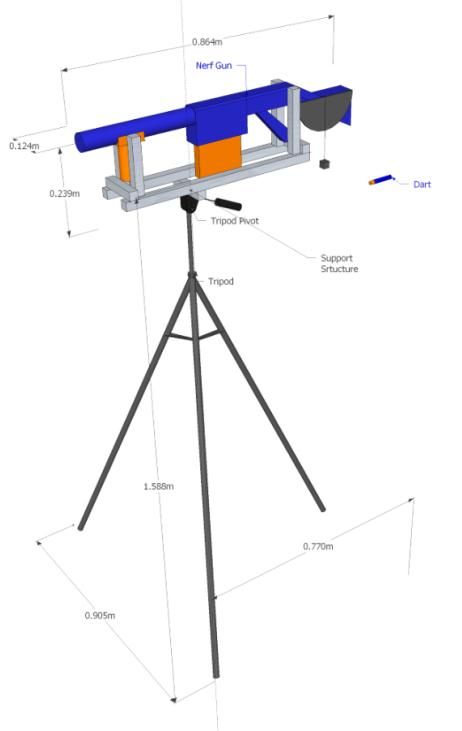
system was predicted to hit the target approximately 30% of the time.The physical build of the launcher, as
seen in Figure 1, consists of several physical
components. A camera tripod was used to
provide a steady base from which to launch
the projectile. Additionally, the tripod allows
the user to easily adjust the firing angle to
the necessary angle calculated by the GUI.
The projectile launcher, a NERF N-Strike
Elite Retaliator Blaster gun, was mounted on
top of the tripod. The gun was mounted on
top of the tripod using an 80/20 frame. The
Figure 1. Final Physical Build Schematic
gun was attached to this frame in a secure
fashion so as to hold the gun steady while firing. The frame was also attached securely to
the tripod. The initial height of the projectile was measured from the floor to the center of
the gun. This height was used because this was where the projectile motion curve began,
as the initial force was applied at this point in the gun. To set the launcher to the
appropriate firing angle, a protractor was attached to the 80/20 frame. Because the 80/20
frame moves with the gun, the protractor accurately represents the angle at which the gun
was aimed.
On the next page, Table 1 displays the items used for the physical portion of the
project, and the prices associated with their purchase or rental. The NERF gun was the
largest cost associated with the project. Many components of the project were rented, and
costs were kept very low as a result.Table 1. Parts and Costs Table
Item Quantity Dimensions Cost
NERF Gun (N-Strike 1 0.86m x 0.24m x 0.12m $24.99
Elite Retaliator)
NERF Projectiles 12 0.07m x 0.01m x 0.01m Come with
Nerf Gun
Tripod Stand 1 0.77m x 1.59m x .91m $2.00 rental
Whiteboard 1 1.07 m x .81m $1.00 rental
80/20 2 7.69 ft total (7.69*.125) $0.96 rental
Protractor 1 .15m x .08m $1.57
Total 24 $30.52
The only major physical design change that
was made involved how the 80/20 frame was
attached to the NERF gun. As seen in Figure 2, the
original concept design called for several vertical
pieces of 80/20 to support the gun. These were to be
attached to the gun in two locations. One set of
vertical pieces was to be attached towards the front of
the gun, and another set was to be attached towards
the back end of the gun. It was decided that these
vertical pieces were unnecessary because they did not
add any stability or support. Additionally, it became
Figure 2. Original Concept Design
clear that the connectors needed to attach these were
unavailable.Underlying concept
The flight of the NERF dart followed a projectile motion; hence, its path was
predicted using kinematic equations. Equation 1 and 2 were used to approximate the
position of the dart in the x and y axes during its flight:
(1)
(2)
where is the initial x position of the gun, is the initial y position of the gun, is the
initial velocity of the dart and is the acceleration of the dart. The initial velocity was
14 m/s as measured using a Photogate sensor. In graphing the velocity of the projectile
throughout its flight, Verlet method was used in calculating Equation 3:
(3)
where is the drag constant and is the initial velocity of the dart. Drag constant b is
described in Equation 4:
(4)
where is the density of air, is the speed of the dart relative to the fluid, is the drag
coefficient of the dart and is the cross-sectional area of the dart. It was assumed that
was 1.2 kg/m3 and the drag coefficient was 0.82.
This project also assumed that energy was not conserved in the system. About
90% of the potential energy of the spring that should be converted into the kinetic energy
of the projectile was lost due to air drag, pressure leakage in the gun barrel and internal
friction of the spring. The amount of potential energy of the spring was measured using
Equation 4:(4)
where is energy loss constant, is the spring constant and is the compression of
the spring. The spring constant is assumed to be approximately 380 N/m and is about
0.9. Meanwhile, Equation 5 is used to calculate the best firing angle to strike desired
target:
(5)
where is the initial position of the gun, is the initial height of the gun, is the
position of the target, and is the height of the target.
Below, Table 2 contains the data from physical testing, which showed that the
accuracy of the GUI prediction decreased with increasing distance from the target.
Table 2. Probability of hitting the target and in plane of the target
Number of Hits Probability
Position of the Total
gun in x-y plane In Plane of Shots In plane of
(m) Target Target Target Target
(6,1.05) 5 4 5 100 80
(8,1.05) 3 2 5 60 40
(10,1.05) 3 2 5 60 40
(12,1.05) 3 1 5 60 20
(14,1.05) 3 2 6 50 33
(15.75,6.05) 4 3 10 40 30One of the limitations of the project is the imperfection of the dart itself, which
caused the dart to veer to the sides instead of traveling in a straight line. Consequently,
the projectile traveled at a distance lesser than the GUI prediction. Another limitation of
this project is that only motion in two dimensions was considered in the GUI prediction.
Graphical User Interface
The group utilized a Graphical User Interface, GUI, with several features to
enhance the abilities of the program. The Nerf Targeting GUI allowed for several inputs
to allow the user complete control of the variables. As seen in Figure 3 below, the
screenshot of the GUI is shown.
Figure 3. GUI ScreenshotPrimarily, the user can input the initial x and y positions, with tags xshootText
and yshootText respectively, and the final x and y positions, with xtargetText and
ytargetText respectively, of the dart to decide where exactly the dart will travel. For the
purpose of testing the GUI, the group kept the initial x position set at 0.0 m. On the other
hand, the group varied the initial y position because the Nerf Gun was mounted on a
tripod either 1.05 m or 6.05 m off the ground, depending on the shot. Furthermore, the
group also altered the initial y position by placing the Nerf Gun and Tripod on the second
level of Stinson Remick and fired the gun onto the floor of the first level atrium. Lastly,
the final x and y positions for the GUI factored in exactly how far the group wanted the
target to be from the initial position. The initial and final x and y positions are two of the
major inputs for the GUI.
While the inputs included the initial and final x and y positions, there were two
other very important inputs for the GUI. The last two inputs the user could use was the
input of the spring constant, in springText, and the type of dart being fired, in dartPopup.
For the spring constant, the group experimentally measured the spring of the Nerf Gun to
be 380 N/m. Additionally, the type of dart being fired affected the coefficient of drag,
which the program factored into the equations. For other shapes, the user could utilize
darts that were cone shaped or short cylinders, choice of Dart 2 and Dart 3 in the drop
down menu of the GUI. Lastly, another feature of the GUI was a Reset button, which
resets the position inputs, graphs and the angle of launch. The inputs of the GUI allowed
for several outputs to completely display the performance of the dart.
The outputs of the GUI included the launch angle (angleText), a graph of the path
of the projectile with respect to x and y position (pathPlot), a graph of the velocity of theprojectile throughout the travel with respect to velocity and time (velocityPlot), and a
graph of the probability of success for the dart to hit the target (succeessPlot). The angle
of launch output gave the needed launch angle to hit the target. Also, the path of
projectile and velocity of projectile graphs gave clear parabolas of the path and velocity
during flight. Lastly, the probability of success graph gave two editable text boxes. The
first box displayed the chance of the dart hitting within the line of the target while the
second box displayed the chance of the dart hitting the target. In conclusion, the outputs
gave a variety of displays to aid the user in understanding the flight of the dart.
The specific set up of the GUI had several choices made to allow the GUI to be
more graphically appealing to the user and easily functional. In order to make the GUI
more appealing, the group added a welcome screen to the GUI, a waitbar, and made the
GUI neat and organized. Furthermore, the majority of the inputs were editable text boxes
to allow the user an infinite variety of inputs, as long as they fall within the parameters of
the equations. The choice of the Pop-up menu was to make the user choose between
specific shapes of darts. Also, the program could also perform with more inputs of drag
coefficients, and the group chose a reset button to give the user a simple way to reset all
the variables. Therefore, the overall GUI had a graphically appealing design with a user-
friendly structure.
Discussion of Performance
Based on our GUI we predicted that from any distance less than roughly 6 meters
away we would hit the target nearly 100% of the time. Naturally, as we moved farther
away our chance of successfully striking the target decreased exponentially. Other than a
minor hiccup due to our gun getting jammed, our demonstration went as predicted by ourGUI. We were able to successfully strike the target from 9 meters away 2 out of 3 times.
The predicted chance of striking the target for each of those shots was 50%. Our balcony
attempt was significantly less accurate as expected but still managed to strike the target 1
out of 4 times, which was exactly what we had predicted.
Under ideal conditions we would be able to strike the target 100% of the time
regardless of distance. Unfortunately, we cannot have ideal conditions. We had to
approximate and verify experimentally the energy loss due to friction in the barrel, the
spring constant, and the drag coefficient of our projectile. This, coupled with the fact that
our projectiles were foam darts, lead to a certain level of inaccuracy. Overall, we
determined that our approximations were close enough to the true values for the purpose
of our project.
In our GUI we allowed the user to change the drag coefficient of the projectile.
We had originally planned on using multiple different shapes for our projectiles but due
to unforeseen difficulties we were unable to modify the darts. Should the user have
different shaped darts we wanted our GUI to still be compatible so we left this
functionality active even though it did not affect our own demonstration.
We could have improved our project through various modifications to the gun.
Since NERF guns are designed for children there are safety mechanisms to prevent them
from firing above a certain speed. By removing these we could have been able to fire
with a higher velocity, which could have been more accurate. We also may have been
able to more accurately test for our spring constant had we had the opportunity to
disassemble our gun.References
"Drag Coefficient." Wikipedia. Wikimedia Foundation, 7 Apr. 2013. Web. 15 Feb. 2013.
.
"Linear Characteristic Graphical Models Resources." Linear Characteristic Graphical
Models Resources. N.p., n.d. Web. 22 Feb. 2013.
.
"NERF: The Spring Constant." YouTube. YouTube, 09 Dec. 2008. Web. 15 Feb. 2013.
.You can also read