ORIONTM Planning Guide - LIMITED USE / LIMITED APPLICATION ELEVATOR - Savaria
←
→
Page content transcription
If your browser does not render page correctly, please read the page content below
ORION
                                             TM

LIMITED USE / LIMITED APPLICATION ELEVATOR

               Planning Guide
        Limited Use / Limited Application Elevator
                    Applicable Codes:

                ASME A17.1, Section 5.2
               CAN/CSA B44, Section 5.2

                      Part No. 000682
                       08-m08-2018
TABLE OF CONTENTS GENERAL 3 PRODUCT DESCRIPTION 4 ORION LU/LA ELEVATOR SPECIFICATIONS 5 CAB TYPE SELECTION SHEET 6 MACHINE ROOM OPTIONS 7 MACHINE ROOM DIMENSIONS 8 HOISTWAY AND PIT ELECTRICAL NOTES 9 CONTROLLER TANK SPECIFICATIONS 10 ORION 48” X 54” TYPE 1 WITH 2 SPEED DOORS 11 ORION 48” X 54” TYPE 2 WITH 2 SPEED DOORS 12 ORION 51” X 51” TYPE 3 (4) WITH 2 SPEED DOORS 13 ORION 42” X 60” TYPE 1 WITH 2 SPEED DOORS 14 ORION 42” X 60” TYPE 2 WITH 2 SPEED DOORS 15 ORION 48” X 54” TYPE 1 WITH 2 SPEED DOORS 16 ORION 48” X 54” TYPE 2 WITH 2 SPEED DOORS 17 ORION 42” X 60” TYPE 1 WITH 2 SPEED DOORS 18 ORION 42” X 60” TYPE 2 WITH 2 SPEED DOORS 19 LOADS ON BUILDING AND PIT LOADING 20 ENTRANCE MOUNTING DETAILS FOR 2 SPEED DOORS WITH DRYWALL CONSTRUCTION 21 ENTRANCE MOUNTING DETAILS FOR 2 SPEED DOORS WITH DRYWALL CONSTRUCTION 22 ENTRANCE MOUNTING DETAILS FOR 2 SPEED DOORS WITH MASONRY CONSTRUCTION 23 ENTRANCE MOUNTING DETAILS FOR 2 SPEED DOORS WITH MASONRY CONSTRUCTION 24 2 SPEED AUTOMATIC DOOR AND GUIDE RAIL INFORMATION 25 PIT AND OVERHEAD CLEARANCE DETAILS 26 ORION STANDARD NOTES 27 SPECIFICATIONS FOR PART 5.3 COMPLIANCE 28 Page 2 of 29 Orion Planning Guide Part No. 000682 08-m08-2018
GENERAL
This planning guide is designed to assist architects, contractors and lift professionals in planning for a Orion Elevator to
meet the requirements of the following codes and standards:
ASME A17.1/CSA B44 2000, Section 5.2
ASME A17.1/CSA B44 2004, Section 5.2
ASME A17.1 2004, Addendum 2005, Section 5.2
ASME A17.1/CSA B44 2007, Section 5.2
ASME A17.1/CSA B44 2004, Addendum 2008, Section 5.2
ASME A17.1/CSA B44 2010, Section 5.2
ASME A17.1/CSA B44 2013, Section 5.2
ASME A17.1/CSA B44 2016, Section 5.2
This unique elevator is designed to help solve accessibility problems in commercial buildings, and meets state and
national codes covering the Limited Use/Limited Application (LULA) elevators.
We strongly recommend you contact the Authority Having Jurisdiction (AHJ) in the region where the equipment will be
installed. Become familiar with all requirements governing the installation and use of elevators in public and private
buildings. It is extremely important for you to know and adhere to all regulations concerning installation and use of
elevators.
DOCUMENT REVISION HISTORY
Initial Release - September 1, 2006
Revised - May 22, 2008
Revised - December 4, 2009
Revised - March 12, 2010
Revised - November 3, 2010
Revised - December 7, 2011
Revised - November 14, 2012
Revised - July 9, 2013
Revised - August 19, 2013
Revised - October 21, 2013
Revised - November 29, 2013
Revised - March 12, 2014
Revised - October 21, 2014
Revised - November 5, 2014
Revised - January 13, 2015
Revised - January 29, 2015
Revised - February 4, 2015
Revised - February 19, 2015
Revised - March 10, 2015
Revised - September 24, 2015
Revised - October 15, 2015
Revised - March 7, 2016
Revised - June 6, 2016
Revised - January 10, 2017
Revised - February 9, 2017
Revised - June 12, 2017
Revised - August 8, 2017
Revised - November 11, 2017
Revised - November 21, 2017
Revised - August 8, 2018
IMPORTANT NOTICE
This Planning Guide provides nominal dimensions and specifications useful for the INITIAL planning of an elevator
project. BEFORE beginning actual construction, be sure to receive application drawings customized with specifications
and dimensions for your specific project.
NOTE: The cab dimensions provided in this manual are based on a PLAM cab.
Lift configurations and dimensions are in accordance with our interpretation of the standards set forth by the codes listed
above. Please consult Savaria or the authorized Savaria dealer in your area for more specific information pertaining to
your project, including any discrepancy between referenced standards and those of any local codes or laws (AHJ).
The dimensions and specifications in this Planning Guide are subject to change (without notice) due to product
enhancements and continually evolving codes and product applications.
• Determine customer’s intention for use.
• Determine code requirements of site.
• Determine installation parameters of site.
• Use page 6 to determine the car type and hoistway size requirements.
• Use pages 7, 8 and 27 to plan for machine room and electrical requirements.
Page 3 of 29
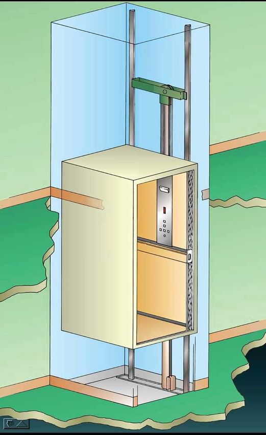
Part No. 000682 08-m08-2018 Orion Planning GuidePRODUCT DESCRIPTION
Overhead Guide
Clearance Rails
⅜” Wire
Rope
Hydraulic Cables
Cylinder
Cab
Operating
Panel
Cab
Pit
Orion in Hoistway
Meets (ADA) Americans with Disabilities Act Requirements
The Orion meets the requirements of the ADA Accessibility Guidelines as a means to provide
public building access.
Design Assistance
With over 30 years of experience. Savaria has the expertise to provide solutions to
practically every design challenge you face. Please call our Customer Service Department
for professional advice at (800)661-5112 or (905)791-5555.
Page 4 of 29
Orion Planning Guide Part No. 000682 08-m08-2018ORION LU/LA ELEVATOR SPECIFICATIONS
Load Capacity 1400 lb (635 kg)
Rated Speed 30 fpm (0.15 mps)
Power Supply (circuit by others) 208 Volt, three-phase, 30 Amps, 60 Hz or 240 Volt, single-phase, 40 Amps, 60 Hz
Lighting Supply (circuit by others) 115 Volt, 15 Amps, 60 Hz
Drive System 1:2 cable hydraulic with slack cable safety device
5 hp submersed motor
Two ⅜” diameter steel aircraft cables
Rope wedge sockets
Cab Size W48” x 54” x H84” (1219 mm x 1371 mm x 2134 mm), Type 1, 2, 3, 4
W42” x L60” x H84” (1067 mm x 1524 mm x 2134 mm), Type 1, 2, 3, 4
W51” x L51” x H84” (1295 mm x 1295 mm x 2134 mm), Type 3, 4
Cab Panel Finish Steel panel cab with optional laminates
Maximum Travel 18 inches (457 mm) to 25 feet (7.6 m) ANSI, up to 40 feet residential and CSA
Control System Automatic user interface; Programmable Logic Controller (PLC)
Operating Temperature: 0 to +50 degrees C (=32 to +122 degrees F)
Humidity: 20 to 80% (non-condensing)
Controller Specs Vibration: 2G, Shock: 11G
Weight: Approx. 90 lbs
Distance between 2 landings 18” (457 mm) minimum
Noise level (typical installation) 73.2 dBA; measured at a height of 1m, distance of 1m, in front of tank, in closed machine room
Normal: 30, Heavy: 75, Excessive: 100
Daily cycle Maximum starts in 1 hour on standard installation: 15
NOTE: Consult your Sales Representative if there’s a chance you may exceed these amounts.
Maximum machine room temperature 120 degrees F (49 degrees C); tank generating ~ 3200 BTU/HR to 6400 BTU/HR
Levels and Openings Up to 6 stops (maximum 6 landing doors on all cab types)
Pit Depth Required 14 inches (355 mm) minimum up to 96 inches (2438 mm)
108 inches (2743 mm) for existing construction without overspeed governor
Minimum Overhead Clearance 120 inches (3048 mm) for existing construction with overspeed governor
134 inches (3404 mm) for new construction
Hall Station and Control Panel Finish Rectangular stainless steel (standard) or brass (optional)
Standard Features 8 lb/ ft or 16 lb/ft T-rail system
Anti-creep device
Architectual white ceiling
Automatic cab ON/OFF lighting
Car top stop switch and car top prop (where required)
Data plates, capacity tags and rope tags
Digital floor and directional indicator
Emergency manual lowering, stop key switch and alarm buttons
Emergency battery back-up for lighting, alarm and emergency lowering
Floor specific battery lowering
Illuminated cab operating buttons
Limited warranty covers the repair or replacement of any defective parts for a period of 36 months
from date of shipment
Magnetic floor selection, stopping and re-levelling
Manual reset slack rope safety switch
Maintenance pit props
Pit switch
Pit clearance switch
Presentation drawings
Pump run timer
Rail sections (8 ft standard or 16 ft optional)
LED lights in stainless steel
Recessed plywood floor
Two 12V, 4AH, sealed no maintenance batteries with 24 V, 4 Amp Smart Charge™ battery charge
Variable speed pressure compensated valve with manual lowering
Upper and lower terminal limits
Options 2 speed sliding doors for drywall or Masonry hoistway finish
2 speed steel doors with infrared closing sensors in black, architectural white or stainless steel
Steel panels with plastic laminate in a variety of colors
15 ft, 20 ft, or 25 ft hose with flow control
90 degree entry/exit cab
Automatic cab gate operator and automatic hoistway door operator
Automatic home landing to pre-selected floor
Brass COP, hall call stations, handrail and recessed down lights
Buffer springs, 15” (381 mm) minimum pit depth required
Conductor cable for hoistway to pump wiring, 40 ft (12.19 m), 60 ft (18.29 m) or
80ft (24.38 m)
Firefighter service - phase 1 and 2 (dependable on applicable code year)
Flow control, overspeed valve and pipe rupture valve
Hands-free telephone
Overspeed governor
Fire recall service
Raised plastic laminated panels in a choice of 7 colors
Recessed stainless steel or brass telephone cabinet
The Orion meets the requirements of multiple ASME A17 code years for a LU/LA Elevator. Contact sales for further information. Page 5 of 29
Part No. 000682 08-m08-2018 Orion Planning GuideCAB TYPE SELECTION SHEET
Type 1 Type 2 Type 3 and 4
IMPORTANT
Finished hoistway dimensions must include the drywall. Determine the fire rating of the
hoistway, the type and layers of sheet rock and build only off the final shop drawings specific
to your project.
Page 6 of 29
Orion Planning Guide Part No. 000682 08-m08-2018MACHINE ROOM OPTIONS
5 ft 0 in. min.
5 ft 0 in. min.
230/208 Disconnect
115 V Cab Lighting Disconnect
Machine Room Light Switch
GFI Duplex Wall Recetacle
Left Hand Position Right Hand Position
Back Position Remote Position
o Machine room must be built in accordance with elevator manufacturer and applicable building codes and
regulations. Adequate ventilation is required to maintain a temperature of 50° to 120°F for output of 3600 BTU
per hour.
o A convenience outlet of 115 VAC 15 Amp single-phase with G.F.I. shall be located next to the light switch in
the machine room (provided and installed by others).
o Provide lockable, in open position, fused disconnect switches located adjacent to the elevator controller.
Fusing must be selectively coordinated. Fuse either 208V three-phase w/30 Amp or 240V single-phase w/40
Amp service; fuse 115V for 15 Amp service for cab lighting. (Must comply with applicable codes.)
o The electrical circuit provided shall be either 30 Amp 208V three-phase or 40 Amp 240V single-phase,
dedicated circuit with equipment ground. The circuit shall terminate on the line side terminal lugs of the
disconnect. The electrical circuit is provided and installed by others.
o Disconnect switch to have auxiliary normally open interlock switch. Interlock equal to Square D EK-300-Z.
o 30” wide x 36” deep work space required in front of the disconnects and the elevator controller.
o Machine room lighting shall be a minimum of 19 foot-candles (204 lux) at working surfaces. The switch
for the light must be within 18” of the strike side of the machine room door. The light must be guarded to
prevent accidental breakage or contact with the hot bulb. The switch, light, wiring, and guard are provided
and installed by others.
o A telephone line circuit is to be provided and installed by others. This circuit shall be brought to the machine
room controller in conduit. This circuit must be connected to a dedicated outside line or a 24 hour central
exchange.
o The elevator controller/pump unit dimensions - 27.5” wide x 62.8” high x 16.15” deep with 39” clear space in
front.
o Machine room access door must be self closing, self locking, key locked and have a spring return latch.
o Consult local building codes for door construction. The door and hardware are both provided and installed by
others.
o Machine room is required to be free of all pipes, wiring and obstructions not related to the operation of the
elevator. Provide a 4 inch conduit from the lift shaft to the remote machine room.
Page 7 of 29
Part No. 000682 08-m08-2018 Orion Planning GuideMACHINE ROOM DIMENSIONS Page 8 of 29 Orion Planning Guide Part No. 000682 08-m08-2018
HOISTWAY AND PIT ELECTRICAL NOTES
o A load bearing wall is required to sustain rail reactions. See page 18 for rail reactions.
o Suggested hoistway pit floor construction consists of an 8“ (203 mm) concrete slab poured on a natural or
compacted soil with a minimum allowable bearing pressure of 1.0 KSF.
o The minimum compressive strength of the concrete at 28 days must be no less than 3000 PSI.
#5 reinforcing steel (grade 60) must be placed at the bottom of the slab in 2 traverse directions and at a
spacing of 12“ (305 mm).
o Hoistway pit floor to support a load of 10 kips (10,000 lbs)/44.48KN (includes impact).
o 108” (2743 mm) minimum overhead clearance required above the top landing floor (for existing construction
without overspeed governor).
o 120” (3048 mm) minimum overhead clearance required above the top landing floor (for existing construction
with overspeed governor).
o 134” (3404 mm) minimum overhead clearance required above the top landing floor (for new construction).
o 14” (356 mm) minimum pit. (A clearance device is provided to attain required 36“ (914 mm) refuge
space).
o Hoistway sizes reflect running and access clearances only. Consult your local AHJ to assure compliance with
local codes.
o Hoistway is required to be free of all pipes, wiring and obstructions not related to the operation of the elevator.
o If a dedicated pit light is required by your local AHJ, please follow the guidelines below for accommodating
this in your hoistway
8¼” Approximate space available for
a dedicated light with guard. We
recommend mounting the light
after the elevator doors have
5”
been installed to ensure adequate
clearance.
15¾”
10”
Type 1 Cab
5”
GFI
Type 2 Cab
The dedicated GFI outlet
9” is approximately 24” up
from the lower landing
finished floor light switch
mounted directly above.
GFI
9” Clear Distance (from inside
finished surface of hoistway to
edge of electrical box).
9”
Page 9 of 29
Part No. 000682 08-m08-2018 Orion Planning GuideCONTROLLER TANK SPECIFICATIONS
Dimensions (inches) H 57” x W 28” x D 17” (approx.)
Minimum Required Clearance in Front (inches) 39”
Valve and Manual Lowering Handle Location Inside tank
Rupture Valve Test T-fitting factory installed
Tank to Controller Wiring Quick connect valve and motor wiring
Controller Layout PLC
Keyed Lock to Tank Yes
Machine Room Required Yes
Tank Capacity (gal/ltr) 15-16.5 gal/57-63 ltr
Max. Dry Weight (lbs/kgs) 147 lbs/55 kg
Max. Filled Weight (lbs/kgs) 312 lbs/117 kg
Operating Environment 50°F - 80°F /10°C - 27°C
Operating Volume 57 dBA
Controller Tank Features
• Hydraulic hose connection ports on either side of the tank
• Built in handles on either side of the tank
• Isolation mounting of pump motor valve assembly minimizes operating noise
PLC Controller Tank
Page 10 of 29
Orion Planning Guide Part No. 000682 08-m08-2018ORION 48” X 54” TYPE 1 WITH 2 SPEED DOORS
Type 1 Finished hoistway dimensions must include the drywall (where applicable).
Determine the fire rating of the hoistway, the type and layers of sheet rock.
Build only from shop drawings specific to your project.
Type 1 - 48” x 54”
w/ 2 Speed Doors
For Masonry or Drywall
Entrance Details, refer
to drawings on pages
21-24
NOTE
Plan view drawing can be reversed for Right Hand applications.
The cab dimensions provided in this manual are based on a PLAM cab.
Page 11 of 29
Part No. 000682 08-m08-2018 Orion Planning GuideORION 48” X 54” TYPE 2 WITH 2 SPEED DOORS
Type 2 Finished hoistway dimensions must include the drywall (where applicable).
Determine the fire rating of the hoistway, the type and layers of sheet rock.
Build only from shop drawings specific to your project.
Type 2 - 48” x 54”
w/ 2 Speed Doors
For Masonry or Drywall
Entrance Details, refer
to drawings on pages
21-24
NOTE
The cab dimensions provided in this manual are based on a PLAM cab.
Page 12 of 29
Orion Planning Guide Part No. 000682 08-m08-2018ORION 51” X 51” TYPE 3 (4) WITH 2 SPEED DOORS
Type 3 or 4 Finished hoistway dimensions must include the drywall (where applicable).
Determine the fire rating of the hoistway, the type and layers of sheet rock.
Build only from shop drawings specific to your project.
Type 3 (4)
51” x 51”
w/ 2 Speed Doors
For Masonry or
Drywall Entrance
Details, refer to
drawings on pages
21-24
NOTE
Plan view drawing can be reversed for Type 4 applications.
The cab dimensions provided in this manual are based on a PLAM cab.
Page 13 of 29
Part No. 000682 08-m08-2018 Orion Planning GuideORION 42” X 60” TYPE 1 WITH 2 SPEED DOORS
Type 1 Finished hoistway dimensions must include the drywall (where applicable).
Determine the fire rating of the hoistway, the type and layers of sheet rock.
Build only from shop drawings specific to your project.
Type 1- 42” x 60”
w/ 2 Speed Doors
For Masonry or Drywall
Entrance Details, refer
to drawings on pages
21-24
NOTE
Plan view drawing can be reversed for Right Hand applications.
The cab dimensions provided in this manual are based on a PLAM cab.
Page 14 of 29
Orion Planning Guide Part No. 000682 08-m08-2018ORION 42” X 60” TYPE 2 WITH 2 SPEED DOORS
Type 2 Finished hoistway dimensions must include the drywall (where applicable).
Determine the fire rating of the hoistway, the type and layers of sheet rock.
Build only from shop drawings specific to your project.
Type 2 - 42” x 60”
w/ 2 Speed Doors
For Masonry or Drywall
Entrance Details, refer
to drawings on pages
21-24
NOTE
The cab dimensions provided in this manual are based on a PLAM cab.
Page 15 of 29
Part No. 000682 08-m08-2018 Orion Planning GuideORION17 48” X 54” TYPE 1 WITH 2 SPEED DOORS
Type 1 Finished hoistway dimensions must include the drywall (where applicable).
Determine the fire rating of the hoistway, the type and layers of sheet rock.
Build only from shop drawings specific to your project.
For Masonry or Drywall
Entrance Details, refer
to drawings on pages
21-24
NOTE
Plan view drawing can be reversed for Right Hand applications.
The cab dimensions provided in this manual are based on a PLAM cab.
Page 16 of 29
Orion Planning Guide Part No. 000682 08-m08-2018ORION17 48” X 54” TYPE 2 WITH 2 SPEED DOORS
Type 2 Finished hoistway dimensions must include the drywall (where applicable).
Determine the fire rating of the hoistway, the type and layers of sheet rock.
Build only from shop drawings specific to your project.
For Masonry or Drywall
Entrance Details, refer
to drawings on pages
21-24
NOTE
The cab dimensions provided in this manual are based on a PLAM cab.
Page 17 of 29
Part No. 000682 08-m08-2018 Orion Planning GuideORION17 42” X 60” TYPE 1 WITH 2 SPEED DOORS
Type 1 Finished hoistway dimensions must include the drywall (where applicable).
Determine the fire rating of the hoistway, the type and layers of sheet rock.
Build only from shop drawings specific to your project.
For Masonry or Drywall
Entrance Details, refer
to drawings on pages
21-24
NOTE
Plan view drawing can be reversed for Right Hand applications.
The cab dimensions provided in this manual are based on a PLAM cab.
Page 18 of 29
Orion Planning Guide Part No. 000682 08-m08-2018ORION17 42” X 60” TYPE 2 WITH 2 SPEED DOORS
Type 2 Finished hoistway dimensions must include the drywall (where applicable).
Determine the fire rating of the hoistway, the type and layers of sheet rock.
Build only from shop drawings specific to your project.
For Masonry or Drywall
Entrance Details, refer
to drawings on pages
21-24
NOTE
The cab dimensions provided in this manual are based on a PLAM cab.
Page 19 of 29
Part No. 000682 08-m08-2018 Orion Planning GuideLOADS ON BUILDING AND PIT LOADING
Seismic zones 0 and 1 Seismic zone 2 Seismic zone 3 or greater
720 lbf 260 lbf 1200 lbf 300 lbf 2400 lbf 400 lbf
Rail reactions do not include safety factors. Applicable safety factors must be considered in hoistway design.
Rails
Rail Bracket Dimensions Support Wall Orientation
R3- Condition I: when fully loaded car hits buffer (bumper)
R4 - Condition II: when safeties engage on rails with 110%
loaded car at governor tripping speed
R5 - Condition III: normal running with 1.2 times impact for
starting and stopping jerks
Page 20 of 29
Orion Planning Guide Part No. 000682 08-m08-2018ENTRANCE MOUNTING DETAILS FOR 2 SPEED DOORS
WITH DRYWALL CONSTRUCTION
Page 21 of 29
Part No. 000682 08-m08-2018 Orion Planning GuideENTRANCE MOUNTING DETAILS FOR 2 SPEED DOORS
WITH DRYWALL CONSTRUCTION
Contractor please note:
Grouting at the sill may be required after the door frames are set.
Page 22 of 29
Orion Planning Guide Part No. 000682 08-m08-2018ENTRANCE MOUNTING DETAILS FOR 2 SPEED DOORS
WITH MASONRY CONSTRUCTION
Page 23 of 29
Part No. 000682 08-m08-2018 Orion Planning GuideENTRANCE MOUNTING DETAILS FOR 2 SPEED DOORS
WITH MASONRY CONSTRUCTION
Contractor please note:
Grouting at the sill may be required after the door frames are set.
Page 24 of 29
Orion Planning Guide Part No. 000682 08-m08-20182 SPEED AUTOMATIC DOOR AND GUIDE RAIL
INFORMATION
52”
88”
4” min. to 8” max.
Measured from Top of
Finished Floor 2 Speed Door Rough Opening
2 Spd Frame
Clear Inside
Lintel
82”
88”
For Metric Equivalents
80”
Multiply inches times 25.4 for mm
Example:
40.25” x 25.4 = 1022.35 mm
Door Frame Elevation
Notes:
1. See hoistway requirements for the location of the
door centerline.
2. Door panels and frame are primed for painting.
Rails ands Sling in Hoistway
Page 25 of 29
Part No. 000682 08-m08-2018 Orion Planning GuidePIT AND OVERHEAD CLEARANCE DETAILS
14” Pit
Depth
A minimum pit depth of 14” is required.
108” Overhead (Existing Construction without OS Governor)
120” Overhead (Existing Construction with OS Governor)
134” Overhead (New Construction)
Page 26 of 29
Orion Planning Guide Part No. 000682 08-m08-2018ORION STANDARD NOTES
HOISTWAY
o The hoistway must be designed and built in accordance with the “Safety Code for Elevators and Escalators”
(ASME A17.1) and all state and local codes.
o Due to close running clearances, the owner/agent must ensure that the hoistway and pit (where provided) are
level, plumb and square and are in accordance with the dimensions on these drawings.
MINIMUM OVERHEAD CLEARANCE
o Owner/agent must ensure the minimum overhead clearance is in compliance with codes.
CONSTRUCTION SITE
o Owner/agent to provide all masonry, carpentry and drywall work as required and shall patch and make good
(including finish painting) all areas where walls/floors may need to be cut, drilled or altered in any way to
permit the proper installation of the lift.
DIMENSIONS
o Contractor/customer to verify all dimensions and report any discrepancies to our office immediately.
STRUCTURAL
o Structural engineer to assure that the building and shaft will safely support all loads imposed by the lift
equipment. Refer to the tables on the installation drawings for loads imposed by the equipment.
o Suitable lintels must be provided by the owner/agent. Door frames are not designed to support overhead wall
loads.
ELECTRICAL
o Power supply with a lockable fused disconnect and auxiliary contact to brake the battery feed, or circuit
breakers with a 3-pole breaker for battery feed required in compliance with electrical code (contact your
Savaria dealer or refer to the table below for OEM part numbers).
Disconnect Switch Types & Accessories Cutler Hammer Federal Pioneer Siemens
1 PHASE 5 H.P. Pump Unit
2 Pole Solid Neutral 240V 1 PH 1HD222N 1622SN ID322
Required Auxiliary Contact DS16CP E1K-1AEV-W94 MSSAK 116
Required Type “D” Fuse (Buss type “FRN” or equal) 2@40 amp 2@40 amp 2@40 amp
3 PHASE 5 H.P. Pump Unit
3 Pole Solid Neutral 208V 3 PH 1HD321N 1332SN ID321
Required Auxiliary Contact DS16CP E1K-1AEV-W94 MSSAK 116
Required Type “D” Fuse (Buss type “FRN” or equal) 3@30 amp 3@30 amp 3@30 amp
Cab Lighting
1 Pole Solid Neutral 120V 1 PH GP 111N 86211 CFN 211
Required Type “D” Fuse (Buss type “T” or equal) 1@15 amp 1@15 amp 1@15 amp
o Permanent power of 240V single-phase 40 Amp or 208V three-phase 30 Amp must be supplied by others
before installation.
o Remote hall call (when supplied) to be installed by the owner/agent at 42” from the landing floor.
ENTRANCES
o Entrance assemblies must be adjusted to align with the platform and interlock equipment. Others to allow an
adequate rough opening.
o Entrance assembly must be securely fastened to walls by the elevator contractor.
Page 27 of 29
Part No. 000682 08-m08-2018 Orion Planning GuideSPECIFICATIONS FOR PART 5.3 COMPLIANCE
PART 1 GENERAL 7. Car top inspection station with UP and DOWN
test switches, emergency stop, light outlet
1.01 SUMMARY 8. Automatic homing to the lowest floor (optional)
A. The product described herein, manufactured by 9. Slack rope safety.
Savaria is an elevator designed and dimensioned
10. Anti-creep device.
to provide Limited Use/Limited Application (LULA)
elevator to suit individual building requirements 11. Overspeed governor (may not be
for use by persons with disabilities. required) – consult AHJ
12. Dual direction leveling.
1.2 REFERENCES
• Upper and lower terminal limit.
A. Elevator shall be designed, manufactured and
installed in accordance with the following standards: • Pump run timer.
1. American National Standards Institute (ANSI). • Pit clearance device (where required)
2. American Society of Mechanical Engineers (ASME). • Automatic battery powered and manual
3.National Electrical Code (NEC) emergency lowering control devices.
Canadian Electrical Code (CEC) • Minimum pressure switch.
4. American Society for Testing Materials (ASTM). • Maintenance stop blocks.
5. American Welding Society (AWS). • (specify option:) Fire Fighters Service (available).
Canadian Welding Bureau (CWB) • (specify option:) Hall lanterns with chime.
• (specify option:) Recessed telephone cabinet
1.3 SYSTEM DESCRIPTION
(brushed stainless steel or brushed brass).
A. 5 hp submersed motor and pump with electronic • (specify option:) Buffer springs (requires 24” pit).
proportional valve assembly; Programmable logic
controller with collective operation; 1:2 roped hydraulic
1.4 QUALITY ASSURANCE
single stage cylinder with line rupture valve.
B. Number of Stops: (specify:) Two to Four. A. Manufacturer: Provide elevator manufactured by
C. Car Configuration: (specify:) straight-thru, a firm with a minimum of 10 years experience in
90° side exit or enter/exit same side. fabrication of elevators equivalent to those specified.
D. Maximum Travel: (specify:) Up to 25’ (7.62 m) B. All designs, clearances, workmanship and
E. Rated Load: (specify:) 1400 lbs. (635 kg) material, unless specifically accepted, shall be in
F. Rated Speed: 30 fpm (.15m/s) accordance with all codes having legal jurisdiction.
G. Car Size: C. All load ratings and safety factors shall meet
1. 48” x 54” (1219 mm x 1372 mm) platform (standard) or exceed those specified by all governing
agencies with jurisdiction and shall be
2. 84” (2134 mm) high ceiling
certified by a professional engineer.
H. Car Walls: (specify:) Steel panels (black or D. Elevator shall be subject to applicable state, local
architectural white)with (optional) raised plastic and city approval prior to installation and subject
laminate panels (contact Savaria for colors). to inspection after installation. Determination
I. Car Ceiling: White panel. of and adherence to these regulations is the
J. Car Lighting: Four recessed lights. responsibility of the elevator contractor.
K. Operating Features: E. Welders certified in accordance with requirements of
1. Car Operating Panel: (specify:) Brushed AWS D1.1 or CWB shall perform all welding of all parts.
stainless steel or brushed brass panel with F. Substitutions: No substitutions permitted.
illuminated automatic controls, keyed light switch,
emergency stop switch and alarm button 1.5 WARRANTY
2. Hall Stations: (specify:) Brushed stainless steel or A. Warranty: Manufacturer shall warrant component
brushed brass panel with illuminated button and parts of the Orion elevator for a period of 36 months
(specify option:) key lock provided at each landing. from shipping date. This warranty only applies to
3. Car Door(s): Fully automatic, side opening, products installed and maintained by a Savaria
sliding car door with electromechanical interlocks, Authorized Dealer in conformance with all applicable
obstruction sensor, and automatic re-open system. local and national codes. The warranty is void if
regular inspection and maintenance of product
4. Hoistway Doors: 1 ½ hour fire rated fully is not being carried out by an Authorized Savaria
automatic side opening, sliding hoistway Dealer in accordance with the recommendations
doors with two side opening panels in steel contained in the Owner’s Manual. It is the Owner’s
frame with electromechanical interlocks. responsibility to keep records of all such service.
5. Handrail: (specify:) Stainless steel or brass.
6. Pit Switch
Page 28 of 29
Orion Planning Guide Part No. 000682 08-m08-2018PART 2 PRODUCT 3.2 EXAMINATION
A. Use field dimensions and approved manufacturer’s
2.1 MANUFACTURER shop drawings to examine substrates, supports
Provide the Orion Commercial LU/LA and other conditions under which this work is
Elevator manufactured by Savaria. to be performed. Do not proceed with work until
Toll Free Number (800) 661-5112 unsatisfactory conditions are corrected.
Phone (905) 791-5555
Fax (905) 791-2222 3.3 INSTALLATION
Web site: http://www.savaria.com A. The Orion elevator shall be installed in
accordance with manufacturer’s instructions
2.2 MATERIAL and as specified and approved by architect.
• Guide Rail: Dual 8 lbs./ft. machined
steel T-rail system. 3.4 DEMONSTRATION
• Wire Rope: Two 3/8” diameter 7 x 19 ga. IWRC A. The elevator contractor shall make a final check of
aircraft cables with rope wedge sockets. the elevator’s operation with the Owner or Owner’s
representative present prior to turning the elevator over
• Sling: Structural and formed steel for use. The elevator contractor shall determine that
plates with guide shoes. operating and safety devices are functioning properly.
• Platform Floor: Unfinished plywood flooring.
END OF SECTION
2.3 FINISHES Intent of specification is to broadly outline equipment
A. Components shall be prepared with required but does not cover details of design and
1) pre-treatment, construction. Dimensions and specifications are subject
to constant change and continually evolving codes and
2) alkaline detergent wash, product applications. For additional technical information,
3) clear water rinse, contact Savaria at (800) 661-5112 or www.savaria.com.
4) iron phosphate coating,
5) clear water rinse and finished with electrostatically
applied and baked thermostatic powder coat
finish. Standard color is architectural white.
2.4 ELECTRICAL SYSTEMS
A. The electrical contractors shall provide:
1. 208V three phase 30 AMP 60 Hz or 230 V single
phase 40 AMP 60 Hz source in the machine area
with manually operated fused line disconnect.
2. 115 VAC, single phase, 15 amp, 60 Hz,
single phase power source with manually
operated fused line disconnect for car lighting
and a light outlet inside the hoistway.
3. Telephone circuit in the machine area.
PART 3 EXECUTION
3.1 ACCEPTABLE INSTALLERS
A. Installers shall be experienced in performing
work of this section who have specialized in work
comparable to that required for this project.
B. Installers shall be certified and
trained by the manufacturer.
Page 29 of 29
Part No. 000682 08-m08-2018 Orion Planning Guide2 Walker Drive Brampton, ON Canada L6T 5E1 Phone: 905-791-5555 Fax: 905-791-2222 Sales: 800-661-5112 www.savaria.com
You can also read