ORNL Neutron Imaging NXS 2022 - Yuxuan Zhang, Jean Bilheux, Jiao Lin, Hassina Bilheux
←
→
Page content transcription
If your browser does not render page correctly, please read the page content below
ORNL Neutron Imaging

 NXS 2022

 Yuxuan Zhang, Jean Bilheux, Jiao Lin, Hassina Bilheux

 July 10-22, 2022

ORNL is managed by UT-Battelle, LLC for the US Department of Energy
The Neutron Imaging Team

 Yuxuan Zhang, Jean Bilheux, Jiao Lin, S. Venkat Shimin Tang, Artificial
 HFIR CG-1D Computational STS CUPI2D Scientist Venkatakrishnan, Adv. Intelligence, Machine
 Scientist Instrument Scientist Reconstruction Learning, Hyperspectral
 /Machine Learning Imaging

 Erik Stringfellow, Mary-Ellen Donnelly, Harley Skorpenske, Jamie Molaison, Hassina Bilheux,
 Imaging SA Imaging SA SNS Group Leader SNS SNAP SA SNS VENUS Scientist

2
Imaging has a broad scientific portfolio
 Soft Matter and Materials for Materials
 Polymers, 3% infrastructure, 3% degradation,
 3%
 Composites, 3%
 Materials science - Biomass and
 General, 17% Biofuels, 3%
 Porous media, 6%

 Nuclear
 Energy materials , materials, 6%
 11%

 Medical
 applications, 6%

 Phase Industrial
 transformations/kin Life applications , 6%
 etics, 11% Fluids , 9% science
 , 9% Earth and
 environmental
 science, 6%

3
Imaging is a Growing Part of the ORNL
 Neutron Sciences Program
 High Flux Isotope Reactor (HFIR)
 Spallation Neutron Source (SNS)
 Intense steady-state neutron flux
 World’s most powerful accelerator-based neutron source
 and a high-brightness cold neutron source
 Techniques such as Bragg-edge imaging are
 being implemented on BL3 SNAP
 diffractometer (VENUS is under construction)

 Dedicated Imaging Instrument (CG-1D)
 Steadily improving capabilities
 Expanded support

 Future CUPI2D beamline at STS (Bragg
 edge and grating interferometry)

4

Bragg edge Scattering Grating Microscopy Radiography,
 Interferometry Computed
 Tomography
 and
 Resonance

 Radiograph of a membrane in a
 proton exchange membrane fuel cell
 (PEMFC) at a resolution of 1.98 μm

 Radial average absolute differential
 macroscopic cross section vs.
 wavevector transfer in Zircaloy-4
 cladding material Radiograph (top) and Dark field Cut through computed tomogram
 Transmission spectra of pure Ni, image (bottom) of 1-10 μm layers of showing internal flow channels in an
 Ni39Cr11, and Inconel 718 powders. steel foil additively manufactured Inconel 718
 turbine blade

 Vertical slice from a neutron
 microtomography dataset showing Transmission radiographs at different
 Bragg edge strain map of SANS raw data of microporous dendritic microstructures of lead, stages of lithiation during the discharge
 additively manufactured Inconel 718 titanium carbide-derived carbon 4 cm x 4 cm x 1 cm thick Al foam voids and gold in a sample of a gold- process. Yellow and green colors
 at 15, 200, 400 and 550 Mpa. (TiC-CDC) at 800 C (invisible unless measured with lead alloy indicate an increase in Li ion content in
 gratings) each cathode
 10-9
 Inferred structure (indirect) Direct structure

 0.1Å 1.0nm 0.1mm 1.0 mm 10.0mm 10 cm
 HFIR CG-1D/MARS (microscopy)
 FTS VENUS (Bragg edge)
 FUTURE PROPOSAL HFIR MERCURY (high penetration/large samples)

5 STS CUPI2D (combined Bragg edge and neutron grating interferometry) STS VENUS (Resonance)
Inferred structure (indirect) Direct structure

 VENUS (FTS epithermal)
 VENUS (FTS thermal,

 2D: hrs
 Heavy element detection: nuclear

 2D: Tens of min to hrs
 cold) materials, geosciences
 Phase transformation
 30 cm x 30 cm

 in crystalline materials
 such as advanced
 Maximum field-of-view

 alloys and natural MERCURY (HFIR epithermal)

 2D: min
 proposal
 materials under

 Future
 Difficult to penetrate materials: Life
 stress, nuclear sciences and biology, large engineering
 materials, energy materials (H-rich materials, thick and
 materials large objects), Nuclear materials, etc.
 One of 8 selected STS
 10 cm x 10 cm

 instruments
 CUPI2D (STS cold) MARS (HFIR cold)

 2D: ms to min
 2D: s to min
 Dynamics: Materials science Thin samples: Micro-defect Current CG-1D
 (energy materials, alloys, etc.), detections and dynamic processes beamline
 biology, etc., under extremes in engineered and natural moved to new
 conditions. materials, magnetic domain position
 mapping, life sciences and biology

 1Å 10 Å 0.5 μm 0.1 mm 0.5 mm 1.0 cm

6 Resolution sensitivity
Neutrons interact uniquely with matter
 Neutron

 • Non-destructive
 • High penetration
 • Sensitive to light
 X-ray
 elements (H, Li,
 etc.)
 • Isotopic contrast

 [M. Strobl et al., J. Phys. D: Appl. Phys. 42 (2009) 243001]
 https://www.psi.ch/en/niag/what-is-neutron-imaging
7
From raw image to normalized image
 Lambert-Beer Law

 Transmission Sample thickness

 - Normalized Image
 1
 = = −
 Raw Dark Field
 0
 = Attenuation co.

 Avogadro
 - 0 constant
 Transmission Density

 Open Beam Dark Field
 =

 I(i, j) - DF(i, j)
 I N (i, j) =
 OB(i, j) - DF(i, j) Total cross-section Molar mass

8
Principle of Bragg edge imaging (using cold neutrons) • Spallation neutron sources discriminate neutron wavelength (or energy) by using the time-of-flight (TOF) technique Wavelength range ~ [1-10 Å] − m ( ) x N A I ( ) = I 0 ( )e m ( ) = t ( ) M 0.55 White-beam (or reactor-based) neutron 0.5 radiograph: (420) Transmission 0.45 sums over all neutron wavelengths 0.4 (220) 0.35 (311) 0.3 (400) 0.25 t1 or λ1 t2or λ2 1.4 1.9 2.4 2.9 tnor λn Wavelength (Angstroms) 1 cm Position of the edge gives the d- spacing of or displacement gives the strain Barton J.P., Bilheux H.Z., Bossi R., Herwig K.W., Santodonato Wavelength-dependent (or TOF) neutron radiographs L., Taylor M., "Chapter 12: Neutron Radiography for (Discrete neutron wavelengths) Nondestructive Testing", Nondestructive Testing Handbook, 9 Fourth Edition: Volume 3, Radiographic Testing (RT) (2019).
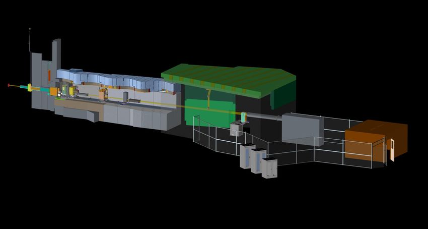
VENUS layout and unique capabilities
 Cave 25 m
 shielding Detectors
 Beam path

 Front-end optics
 buried in shielding

 Beam stop

 Control Hutch

 Bragg edge imaging:
 20 x 20 cm2, spatial resolution ~ 100 µm,
 time resolution is 5 µs.
 Resonance imaging:
 4 x 4 cm2, spatial resolution ~ 150 µm, time Radiological
 resolution is 150 ns. Sample area Materials Area
 (RMA)

10
Preparing for an imaging experiment

 • Predict overall transmission in your sample (iNEUIT)
 • Contact instrument team to optimize your experimental
 measurements (detector, SNR, sample environment, etc.)
 • Contact computational instrument scientist to discuss data
 processing and analysis requirements (Python Jupyter
 notebooks)

11
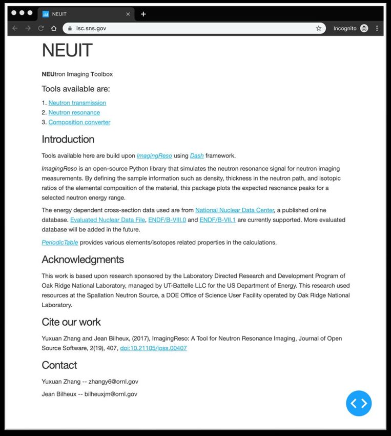
Experiment planning tools: NEUIT (NEUtron Imaging Toolbox)
 • Tools available:
 1) Neutron transmission
 Compute white-beam transmission
 2) Neutron Resonance
 Simulate energy-dependent signal
 3) Composition convertor
 Perform wt. % at. % conversion

 • Nuclear database supported
 – ENDF/B-VIII.0 (BNL)
 – ENDF/B-VII.1 (BNL)

 • Elemental/isotopic info
 – PeriodicTable 1.5.0 (NIST)
12
NEUtron Imaging Toolbox (NEUIT, https://neuit.sns.gov/ )
 For white-beam imaging at CG-1D

 (static)

 (demo)
13
NEUtron Imaging Toolbox (NEUIT, https://neuit.sns.gov/ )
 For resonance imaging

 (demo)
14 (static)
Jupyter Notebooks Demonstration

 • Samples: Ni and Cu powders in Al cans measured at SNS BL-03
 SNAP
 • Goals:
 – Load and normalized data in iBeatles software
 – Plot and Identify Bragg edges
 – Fit Bragg edges
 – Calculate d-spacing

15
How to get to analysis server and start iBeatles

 • On a web browser, type “analysis.sns.gov”
 • Enter username and password
 • On analysis server, open a terminal window
 • Type: /SNS/users/j35/bin/start/iBeatles

16
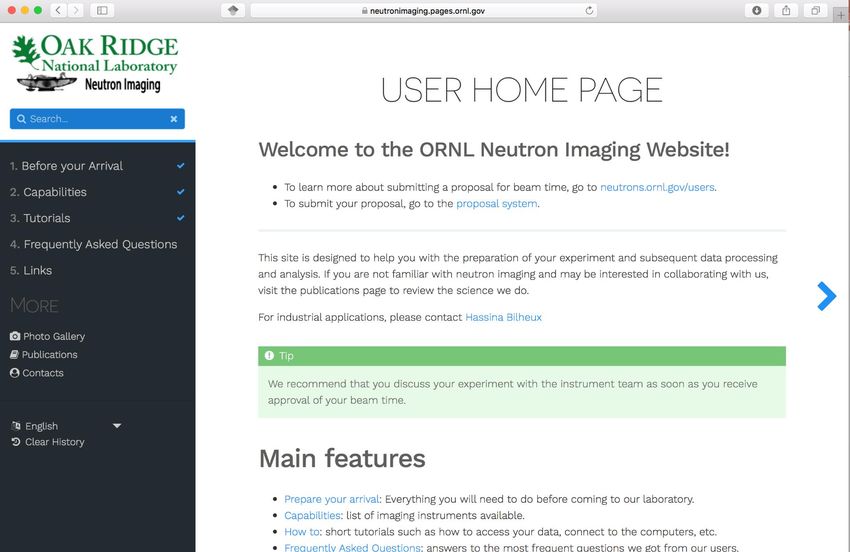
We have a user home page with instructions and tutorials

17
Step-by-step tutorials
 with animated
 demonstrations

 Something you want to
 see on our user
 website? Contact Jean
 Bilheux
 bilheuxjm@ornl.gov

 https://neutronimaging.pages.ornl.gov/
18
This week’s imaging experiment: time-of-flight neutron
 grating interferometry
 • International collaboration between:
 – Markus Strobl and Matteo Busi, Paul Scherrer Institute, Switzerland
 – Simon Sebold, TUM-FRM-II, Germany
 – ORNL neutron imaging team

 • We are measuring the small angle scatter the sample produces when
 interacting with neutrons:
 – This is called the dark field imaging technique
 – We are using a symmetric grating system (i.e., equidistance between the 3
 gratings) because it can accept a broad band of neutrons will keeping good
 visibility

19
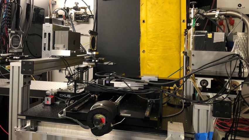
This week’s imaging experiment: time-of-flight neutron
 grating interferometry
 G0 G1 G2
 (25 m period) (12.5 m period) (25 m period)

 NEUTRONS

 Sample
 position

20
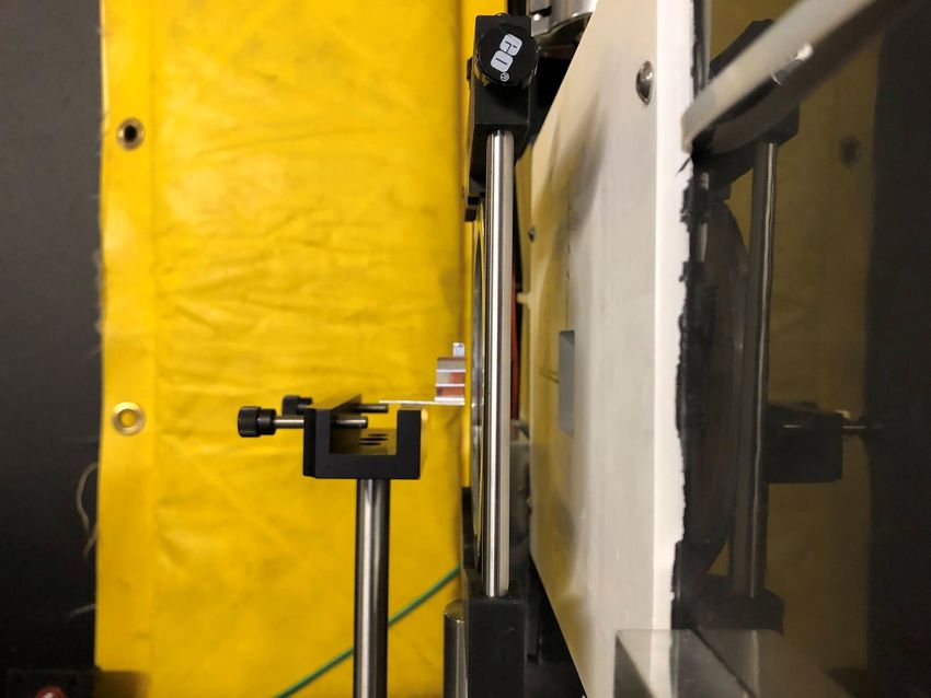
G2
 (25 m period)

 Detector
 Samples
 NEUTRONS

 2 cm

21
Modulation pattern on
 every detector pixel
 obtained by stepping G1
 perpendicular to beam

 = Ls /p
 V = (Imax - Imin)/(Imax + Imin)
 Grünzweig, C., Quantification of the neutron dark-field imaging signal in grating interferometry. Physical Review B - Condensed Matter and
 Materials Physics, 88(12), 1–6. https://doi.org/10.1103/PhysRevB.88.125104
 Kim, Y.; Valsecchi, J.; Oh, O.; Kim, J.; Lee, S.W.; Boue, F.; Lutton, E.; Busi, M.; Garvey, C.; Strobl, M. Quantitative Neutron Dark-Field Imaging
 of Milk: A Feasibility Study. Appl. Sci. 2022, 12, 833. https:// doi.org/10.3390/app12020833
22
Example of DFI Data Analysis

 Visibility is related to real-space correlation

 For dilute solution of spherical particles
 Volume Scattering length
 Radius
 Cross section fraction density contrast

 Correlation length

 Strobl, M. (2015) ‘General solution for quantitative dark-field contrast imaging with
 grating interferometers’, Scientific Reports, 4(1), p. 7243. Available at:
 https://doi.org/10.1038/srep07243.

 Strobl, M. et al. (2016) ‘Wavelength-dispersive dark-field contrast: micrometre structure
 resolution in neutron imaging with gratings’, Journal of Applied Crystallography, 49(2),
23 pp. 569–573. Available at: https://doi.org/10.1107/S1600576716002922.
Artistic rendering of VENUS

 Cave

 Chopper shelf

 In the spirit of “One ORNL”, VENUS colors
 are “ORNL-green” and white.

24
CUPI2D’s Current Conceptual Design
 Optics
 @26.5m from Elevator No. 2
 Optics moderator
 @18.8m from
 moderator Elevator No. 1

 Pedestal supports
 Recessed additional flight tube
 rail system to get as close as
 Side Access possible to sample
 provided

25
26
You can also read