Protection of Power Transformers Against Geomagnetically Induced Currents
←
→
Page content transcription
If your browser does not render page correctly, please read the page content below
SERBIAN JOURNAL OF ELECTRICAL ENGINEERING
Vol. 8, No. 2, November 2011, 333-339
UDK: 621.314.22:621.316.97 DOI: 10.2298/SJEE1103333G
Protection of Power Transformers Against
Geomagnetically Induced Currents
Vladimir Gurevich1
Abstract: The article examines the problem of saturation and failure of power
transformers under geomagnetically induced currents and currents of the E3
component of high-altitude nuclear explosions. It also describes a special
protective relay reacting on DC component in the transformer neutral current.
Keywords: Solar storm, Magnetosphere, Geomagnetic induced current, Iono-
sphere, Transformer saturation, Relay protection.
1 Introduction
Geomagnetic induced currents are the ground currents generated by the
geomagnetic disturbances in the Earth's magnetosphere. These currents are also
induced in long buried metal objects, such as pipelines, railroad rails or cables.
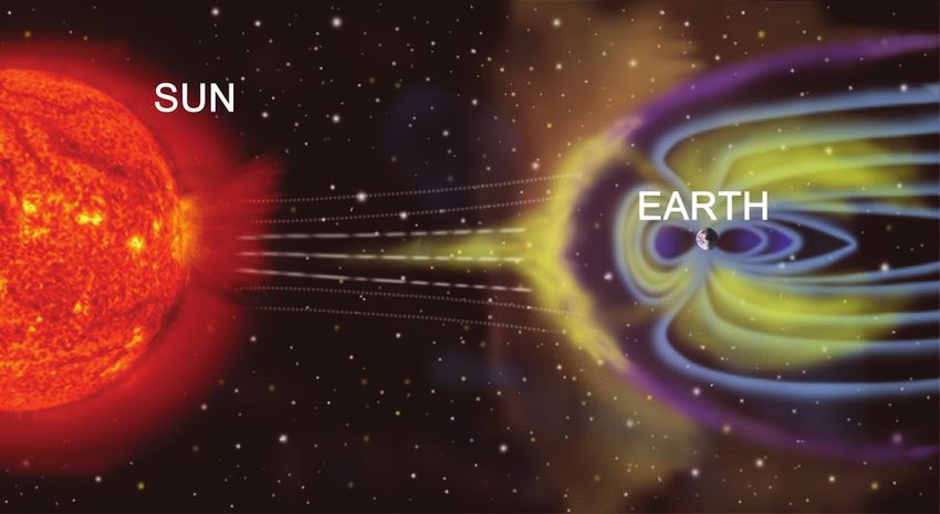
Severe disturbances in the magnetosphere of the Earth arise during solar storms
and the resultant emission of huge amount of ionized plasma (the so-called
“solar wind”) striking the Earth, see Fig. 1.
Fig. 1 – The distortion of the Earth's magnetic field under the solar plasma ejection.
1
Central Electric Laboratory, Israel Electric Corp., POB 10, Haifa 31000, Israel
E-mail: vladimir.gurevich@gmx.net
333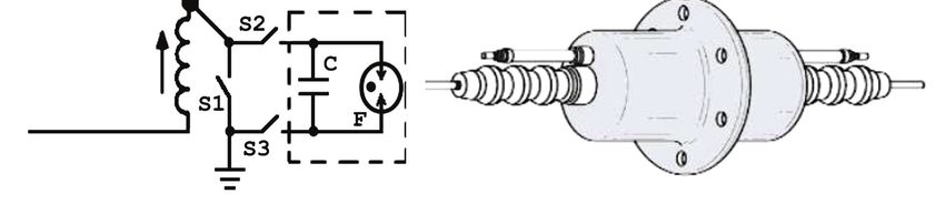
V. Gurevich

     The magnetic field of Earth and its rotation around its axis generate
continuous electric currents in the Earth's ionosphere surrounding the planet a
few hundreds kilometers above the Earth's surface.
     The currents are maintained by the persistent generation of a large number
of charged particles – ions, and free electrons radiating from the molecules of
atmospheric gases broken down by solar radiation. These electrical currents
have a significant influence on the Earth's magnetic field generation.
     During the solar storms, extremely powerful streams of protons and
electrons from the solar plasma sharply increase the electrical currents flowing
in the ionosphere. Aside from the rapid changes in Earth's magnetic field, such
abrupt current changes generate geomagnetically induced currents and induce
high currents in long power transmission lines. These induced currents are
looped through the grounded neutrals of power transformers, see Fig. 2.
     Since such currents are of a very low frequency, their flow through the
windings of power transformers saturates the magnetic cores of transformers
and leads to the sharp decrease in transformers impedance. As is known, the
constant component of the power transformer current also appears at the power
transformer switching-on, so the protective relays of power transformers are
usually offset from the current constant component and do not react to it.

                 Fig. 2 – Diagram of currents in electric mains and
                  ground induced by ionosphere electric currents.

     In addition, a constant current (or a current of a very low frequency) is
practically non-transmissible through the current transformers. Thus, the
traditional protective relay will not respond to the induced currents saturating

                                       334
Protection of Power Transformers against Geomagnetically Induced Currents
the transformer and the transformer will just burn out. In the past there have
been many cases of power transformers burnt out under the geomagnetic
currents induced during solar storms. For example, in 1989 a moderate solar
storm made the ultrahigh voltage power transformers inoperative and benighted
the Canadian province of Quebec for 9 hours. The same storm disabled an
ultrahigh voltage power transformer at the Salem nuclear power plant in New
Jersey, USA. On April 29, 1994, shortly after the beginning of the impact of the
solar wind, the strong geomagnetic storm completely deactivated the ultrahigh
voltage power transformer at the Yankee nuclear power plant in Maine. On
March 24, 1940, a major geomagnetic storm temporarily disrupted the electric
power supply in some regions of states of New England, New York,
Pennsylvania, Minnesota, Quebec and Ontario, and incapacitated 80% of all
telephone lines in Minneapolis, Minnesota [1].
The scientists of NASA expect unusually strong solar storms in 2012 (or in
2013 according to some forecasts). According to these forecasts [1] strong
magnetic storms causing failures of the power systems all over the world are
expected in coming years. Such failures could last from several hours to several
months (due to a lack of backup power transformers in many power systems). It
can result in major collapse for the humanity since we are too dependent on
modern technologies and too vulnerable to disasters of this kind.
The E3 component of high-altitude nuclear explosion [2, 3] has a similar
physical affect on power transformers and is considered by the militaries of
many countries as the so-called "non-lethal weapon" aimed at destroying the
infrastructure rather than killing people which makes it particularly attractive.
2 Power Transformer Protection
The power transformers differ from the electronic devices, also exposed to
damage under such impacts, in their impossibility of quick change in case of
failure [4, 5, 6]. In the context of the foregoing, it becomes clear that it is
important to protect power transformers against damage under geomagnetically
induced currents of low frequency.
One of the solutions proposed by Western scientists is to include a current
limiting capacitance (i.e., powerful capacitor) in the transformer’s neutral.
Elements of this type transmit alternating current of the mains’ frequency
(generated by asymmetry of the phase current) under normal operation but
block the flow of the low-frequency geomagnetically induced currents. Some
Western sources even give the cost of such current limiting elements (it is about
40,000 USD) and comment that presently the Congress is considering the
question of investing 150 million USD in the installation of such elements on
the most important power transformers. The major problem of this solution is
335V. Gurevich
the generation of the extremely high voltages on such elements under short-
circuits in the mains (we are speaking of power transformers of 110 kV and
higher).
Fig. 3 – Protection of the power transformer against the low-frequency
induced currents based on the power elements included in the neutral,
proposed by Western specialists [7].
3 High Power Protective Installation
To solve the problem the [7] proposes using special super high-power cold
cathode electron tubes, short-circuiting the capacitor under voltage buildup and
allowing the short-circuit currents of dozens of kA, see Fig. 3.
The installation of a powerful capacitor with super high power electron
tube (type 4275 Bi-Tron™, 30 kV, up to 75 kA) also requires using additional
switching devices S1, S2, S3, needed to connect the unit to or disconnect it from
the neutral of the power transformer. Generally, it appears to be a quite massive
and very expensive device which will unlikely be widely used due to its high
cost.
4 Special Protective Relay
We, on the other hand, propose another type of the protection of high-
power transformers against the low-frequency geomagnetically induced currents
using a special relay containing no microelectronic components and based on
discrete high-voltage elements [8] resistant to electromagnetic interferences and
surge overvoltage, see Fig. 4.
336Protection of Power Transformers against Geomagnetically Induced Currents
a) b) c)
Fig. 4 – Relay protecting the power transformer against the low-frequency
geomagnetically induced currents in the neutral circuit.
Fig. 4a shows the operational principle of the relay sensitive to the DC
component in the power transformer neutral and insensitive to the widely
varying AC component.
The relay consists of a reed switch, RS, with a coil placed on the cable
(bus) that connects the transformer neutral to the grounding point perpendicular
to the axis of the cable, and a conventional toroidal current transformer, CT,
installed on the same cable.
If there is no DC current in the neutral the magnetic field of the cable (bus)
acting directly on the reed switch, this is fully compensated by the magnetic
field of the coil put on the reed switch and powered by the current transformer.
AC current changes in the neutral lead proportionally to the changes in both
magnetic fields acting on the reed switch, and to their compensation. Under
high DC currents in the neutral (over 10–20A), the balance of the magnetic
fields acting on the reed switch is offset: the magnetic field of the cable (bus)
still acts while the compensating magnetic field of the coil energized by the
337V. Gurevich
current transformer is disabled as the DC component of the current is not
transformed by the current transformer. This leads to reed switch activation.
The real relay circuit includes an additional output amplifier installed on VS
thyristor, varistor RU and the R1C1 all protecting the thyristor from
interferences and voltage surges, see Fig. 4b. The relay is equipped with a
continuous electrostatic shield and a ferromagnetic shield with the only window
on the cable side next to the reed switch and is connected to the circuit of the
CB switch trip coil through a special twisted-pair control cable with the
combined multi-layer shielding grounded at both ends [4, 5, 6] and resistant to the
electromagnetic pulses [2, 3]. The relay can be constructed on miniature high-
voltage vacuum reed switches, for example, of type KSK-1A85 (manufactured
by Meder Electronics), with the electric strength of insulation between the
contacts of 4000V and the bulb having a diameter of 2.75 mm and length of 21
mm. This reed switch is capable of switching loads up to 100W (the maximum
switching voltage is 1000V, the maximum switching current is 1A) with the
response time of 1 ms and a maximum sensitivity of 20A. Additional
ferromagnetic elements (magnetic field concentrators) located next to the reed
switch can be used to increase the sensitivity. To get a relay with lower
sensitivity and a higher pickup, the longitudinal axis of the reed switch should
form a non-perpendicular angle to the axis of the cable on which it is installed.
The thyristor should also be miniature and of high-voltage, e.g., of type
SKT50/18E (manufactured by Semicron), with a maximum voltage of 1800V
and maximum continuous current of 75A, and must withstand high rates of
voltage rise (1000V/µs) under a wide operating temperature range
(–40, +130ºC). The power circuit of the trip coil is equipped with storage
capacitor C3 enabling switch activation even under the loss of operating
voltage. The R2C2 in series is designed to further enhance the immunity of the
device. Capacitor C2 provides a certain delay of the thyristor switch-on,
preventing it from unlocking under the powerful impulse noise.
Application of the discrete high-voltage components instead of
conventional microelectronics in the relay ensures its high reliability under
powerful electromagnetic interferences and surge voltages specific to solar
storms and electromagnetic pulses.
The purpose of this article was to identify the problem and present a simple
solution. For this end we have described a relay design to demonstrate its
general concept only. It is obvious that the described device can be
supplemented by signal relay (blinker) registering the response, time delay
device, reed switch sensitivity control unit, reinforced insulation [9], etc. We
believe that the proposed solution is more than adequate and far cheaper to
implement that other proposed solutions.
338Protection of Power Transformers against Geomagnetically Induced Currents
5 References
[1] A.A. Buralkov, V.V. Kibardin: About Effects of Solar Storms on Reliability of Energy
Systems, Scientific and Technical Congress “Worldwide Power Industry”, Krasnoyarsk,
Russia, June 2010, pp. 32 – 33. (in Russian)
[2] V.I. Gurevich: Stability of Microprocessor Relay Protection and Automation Systems
against Intentional Destructive Electromagnetic Impacts Part I, Components and
Technologies, No. 4, 2011, pp. 116 – 122. (in Russian)
[3] V.I. Gurevich: Stability of Microprocessor Relay Protection and Automation Systems
against Intentional Destructive Electromagnetic Impacts Part II, Components and
Technologies, No. 5, 2011, pp. 129 – 136. (in Russian)
[4] V.I. Gurevich: Problems of Electromagnetic Impacts on Digital Protective Relays,
Components and Technologies Part I, No. 2, 2010, pp. 80 – 84. (in Russian)
[5] V.I. Gurevich: Problems of Electromagnetic Impacts on Digital Protective Relays,
Components and Technologies Part II, No. 3, 2010, pp. 91 – 96. (in Russian)
[6] V.I. Gurevich: Problems of Electromagnetic Impacts on Digital Protective Relays,
Components and Technologies Part III, No. 4, 2010, pp. 91 – 96. (in Russian)
[7] J.G. Kappenman, S.R. Norr, G.A. Sweezy, D.L. Carlson, V.D. Albertson, J.E. Harder, B.L.
Damsky: GIC Mitigation: A Neutral Blocking/Bypass Device to Prevent the Flow of GIC in
Power Systems, IEEE Transaction on Power Delivery, Vol. 6, No. 3, July 1991, pp. 1271 – 1281.
[8] V.I. Gurevich: Electronic Devices on Discrete Components for Industrial and Power
Engineering, CRC Press, New York, USA, 2008.
[9] V.I. Gurevich: Protection Devices and Systems for High-voltage Applications, Marcel
Dekker, New York, USA, 2003.
339You can also read