POST ANCHOR INSTRUCTION MANUAL - SAFEWAZE
←
→
Page content transcription
If your browser does not render page correctly, please read the page content below
020-4029
                                           Post Anchor
                                        Instruction Manual

       WARNING
       This product is part of a personal fall arrest, work positioning, fall restraint, or rescue system. The manufacturer’s instructions must be
       provided to users of this equipment. The user must follow the manufacturer’s instructions for each component of the system. The user
       must read and understand these instructions before using this equipment. Manufacturer’s instructions must be followed for proper use
       and maintenance of this equipment. Alterations to this product, misuse of this product, or failure to follow instructions may result in
       serious injury or death.

       IMPORTANT
       Questions regarding the use, care, or suitability of this equipment for your application? Contact Safewaze.

       IMPORTANT
       Record initial usage of product on Page 2, and Page 10. Competent Person inspections are required to be documented in the Inspection
       Log Table on Page 10.

                                                                                                                                        Page 1
2068                                                   V1.0 2021 Copyright Safewaze
TABLE OF CONTENTS
1 INTRODUCTION..................................................................................... 3
2 DESCRIPTION........................................................................................ 3
3 APPLICABLE SAFETY STANDARDS..................................................... 3
4 WORKER CLASSIFICATIONS................................................................ 3
5 SPECIFIC ANCHOR APPLICATIONS..................................................... 4
6 CAPACITY............................................................................................... 4
7 STRUCTURE REQUIREMENTS............................................................. 4
8 LIMITATIONS........................................................................................... 5
9 COMPATIBILITY OF CONNECTORS..................................................... 6
10 MAKING CONNECTIONS....................................................................... 7
11 COMPONENTS AND SPECIFICATIONS................................................ 8
12 INSTALLATION AND USE......................................................................8-9
13 INSPECTION........................................................................................... 9
14 INSPECTION LOG................................................................................. 10
15 SAFETY INFORMATION......................................................................10-11
16 LABELING.............................................................................................. 11
User Information
Date of First Use:
Serial#:
Trainer:
User:
Do not throw away these instructions!
Read and understand these instructions before using equipment!
Page 2
V1.0 2021 Copyright Safewaze1 - Introduction
Thank you for purchasing the Safewaze 020-4029. This manual must be read and understood in its
entirety, and used as part of an employee training program as required by OSHA or any applicable
state agency.
This manual and any other instructional material must be available to the user of the equipment.
The user must understand how to safely and effectively use the 020-4029, and all fall protection
equipment used in conjuction with the 020-4029.
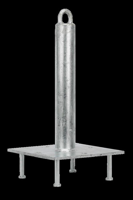
2 - Decscription
The 020-4029 Post Anchor is a single point anchor with a total height of 18”. The PFAS connection
point is a Welded Eye located at the top of the post. The 020-4029 is designed for embedment and
permanent use in a concrete application. The post comes equipped with 4 studs that extend
downward from the baseplate for installation into concrete during pour operations. The concrete must
be a minimum of 3,000 psi with a minimum thickness of 6”. Concrete must be allowed to properly
cure prior to use of the 020-4029. Use of the 020-4029 prior to curing of concrete can result in
serious injury or death.
3 - Applicable Safety Standards
When used according to instructions, this product meets or exceeds all applicable OSHA 1926
Subpart M, OSHA 1910, ANSI Z359.1-2007, and ANSI A10.32-2012 standards for fall protection.
Applicable standards and regulations depend on the type of work being done, and also might include
state-specific regulations. Refer to local, state, and federal (OSHA) requirements for additional
information concerning the governing of occupational safety regarding Personal Fall Arrest Systems
(PFAS).
4 - Worker Classifications
Understand the definitions of those who work in proximity of or may be
exposed to fall hazards.
Qualified Person: A person with an accredidated degree or certification, and with extensive
experience or sufficient professional standing, who is considered proficient in planning and reviewing
the conformity of fall protection and rescue systems.
Competent Person: A highly trained and experienced person who is assigned by the employer to
be responsible for all elements of a fall safety program, including, but not limited to, its regulation,
management, and application. A person who is proficient in identifying existing and predictable
hazards, and who has the authority to stop work in order to eliminate hazards.
Authorized Person: A person who is assigned by their employer to work around or be subject to
potential or existing fall hazards.
It is the responsibility of a Qualified or Competent Person to supervise the job site and
ensure safety regulations are complied with.
Page 3
V1.0 2021 Copyright Safewaze5 - Specific Anchor Applications
Personal Fall Arrest: The 020-4029 is designed as an anchor point to support
a maximum of 1 Personal Fall Arrest System (PFAS) when utilized for fall
protection applications. The structure to which the anchor is attached must
withstand loads applied in the directions permitted by the system of at least
5,000 lbs. Maximum allowable free fall is 6’.
Restraint: The 020-4029 is authorized for use in Restraint applications. The
structure to which the anchor is attached must withstand loads applied in the
directions permitted by the system of at least 1,000 lbs NO free fall is
permitted. Restraint systems may only be used on surfaces with slopes
up to 4 / 12 (vertical / horizontal). For Restraint applications, the allowable
attachment points to harness are Dorsal D-ring, Chest D-ring, Side D-rings,
and Shoulder D-rings.
Work Positioning: The 020-4029 is authorized for use in Work Positioning
applications. Work Positioning allows a worker to be supported during
suspension while freeing both hands to conduct work operations. The structure
to which the Anchor is attached must withstand loads applied in the directions
permitted by the system of at least 3,000 lbs. Maximum allowable free fall is 2’.
For positioning applications, the allowable attachment points to harness are the
Side D-rings.
Rescue/Confined Space: The 020-4029 is authorized for use in
Rescue/Confined Space applications. Rescue systems are utilized to safely
recover a worker from a confined location or after exposure to a fall.
Composition of rescue systems can vary based upon the type of rescue
involved. The structure to which a Anchor is attached must withstand loads
applied in the directions permitted by the system of at least 3,000 lbs. NO free
fall is permitted. For rescue applications, the allowable attachment points to
harness are Dorsal D-ring, Chest D-ring and Shoulder D-rings.
All above referenced applications have a worker weight capacity range of
ANSI 130-310 lbs (including all clothing, tools, and equipment), OSHA 420 lbs.
6 - Capacity
The 020-4029 is ANSI compliant with a specified single user weight capacity of 310 lbs. (Including
Tools, Closthing etc.). This product is also OSHA compliant with a specified single user capacity of
420 lbs. (Including Tools, Clothing, etc.).
7 - Structure Requirements
The structure to which the 020-4029 is attached must be capable of withstanding a 90,000 in-lbs
(10,169 N m) moment, and a 5,000 lbf (2,268 kg) vertical load. Installation of the 020-4029 must
comply with local regulation standards, and be approved by a Qualified Person before use.
Page 4
V1.0 2021 Copyright SafewazeUse care when selecting the anchorage installation location. Structural strength, obstructions in the
users fall path, and swing fall hazards must all be considered prior to installation. A Qualified Person
can determine if a structure is capable of withstanding the applied Maximum Arrest Force (MAF) of
the Personal Fall Arrest System (PFAS) with a Safety Factor of at least two.
8 - Limitations
Fall Clearance: There must be sufficient clearance below the anchorage connector to arrest a fall
before the user strikes the ground or an obstruction. When calculating fall clearance, account for a
MINIMUM 2’ safety factor, deceleration distance, user height, length of lanyard/SRL, and all other
applicable factors. (See Figure 1)
FIGURE 1
For all applications: worker weight capacity range
(including all clothing, tools, and equipment) is
ANSI 130-310 lbs., OSHA 420 lbs.
Fall Clearance Diagram
***Diagram shown is an example
fall clearance calculation ONLY.
Lanyard Length
(6’ - Minus Height of Post)
(4.5’ Total)
Original Lanyard Working
Length prior to a fall event with
energy absorber deployment
Leading Edge
Leading Edge
Deceleration/Elongation
Required distance (5’ Total)
distance
from
Anchorage Harness Stretch
(17.5’ Total) (1’ Total)
Height of harness dorsal
D-ring from worker’s feet
(5’ Total)
Safety factor
(2’ Total)
Page 5
V1.0 2021 Copyright SafewazeSwing Falls: Prior to installation or use, make considerations for eliminating or minimizing all swing
fall hazards. Swing falls occur when the anchor is not directly above the location where a fall occurs.
Always work as close to in line with the anchor point as possible. Swing falls significantly increase
the likelihood of serious injury or death in the even of a fall. (See Figure 2)
FIGURE 2
A
FALL-ARREST
LL
FA
NG
S WI
9 - Compatibility Of Connectors
Connectors are compatible with connecting elements when they have been designed to work
together in such a way that their sizes and shapes do not cause their gate mechanisms to
inadvertently open regardless of how they become oriented. Connectors (hooks, carabiners, and
D-rings) must be capable of supporting at least 5,000 lbs. (22.2 kN). Connectors must be compatible
with the anchorage or other system components (see Figure 4). Do not use equipment that is not
compatible. Non- compatible connectors may unintentionally disengage (see Figure 3). Connectors
must be compatible in size, shape, and strength. Self-locking snap hooks and carabiners are
required by ANSI Z359 and OSHA guidelines. Contact Safewaze if you have any questions about
compatibility.
NOTE: SOME SPECIALTY CONNECTORS HAVE ADDITIONAL REQUIREMENTS.
CONTACT Safewaze WITH QUESTIONS.
FIGURE 3 - UNINTENTIONAL DISENGAGEMENT
1-
Non-compliant part 4 - and parts disengage.
3 - gate opens
2 - gate presses
against
non-complaint
part
Using a connector that is undersized or irregular in shape (1) to connect a snap hook or carabiner
could allow the connector to force open the gate of the snap hook or carabiner. When force is applied,
the gate of the hook or carabiner presses against the non-compliant part (2) and forces open the gate
(3). This allows the snap hook or carabiner to disengage (4) from the connection point.
Page 6
V1.0 2021 Copyright Safewaze10 - Making Connections
Snap hooks and carabiners used with this equipment must be double locking and/or twist lock.
Ensure all connections are compatible in size, shape and strength. Do not use equipment that is not
compatible. Ensure all connectors are fully closed and locked.
Safewaze connectors (snap hooks and carabiners) are designed to be used only as specified in each
product’s user’s instructions. See figure 4 for examples of inappropriate connections. Do not connect
snap hooks and carabiners:
• To a D-ring to which another connector is attached.
• In a manner that would result in a load on the gate (with the exception of tie back hooks).
• NOTE: Large snap hooks must not be connected to objects which will result in a load on the
gate if the hook twists or rotates, unless the snap hook complies with ANSI Z359.1-2007 or ANSI
Z359.12 and is equipped with a 3,600 lb (16 kN) gate. Check the marking on your snap hook to
verify its compatibility.
NOTE: Large throat snap hooks must not be connected to standard size D-rings or similar
objects which will result in a load on the gate if the hook or D-ring twists or rotates, unless
the snap hook complies with ANSI Z359.1-2007 or ANSI Z359.12 and is equipped with a
3,600 lb (16 kN) gate. Check the marking on your snap hook to verify that it is appropriate
for your application.
• In a false engagement, where features that protrude from the snap hook or carabiner catch on the
anchor, and without visual confirmation seems to be fully engaged to the anchor point.
• To each other.
• By wrapping the web lifeline around an anchor and securing to lifeline except as allowed for Tie
Back models.
• To any object which is shaped or sized in a way that the snap hook or carabiner will not close and
lock, or that roll-out could occur.
• In a manner that does not allow the connector to align properly while under load.
FIGURE 4 - INAPPROPRIATE CONNECTIONS
Page 7
V1.0 2021 Copyright Safewaze11 - Components and Specifications
FIGURE 5 - COMPONENTS AND SPECIFICATIONS
5,000 lb Ultimate
Load in All
Directions
Connection Point
High Strength
Steel Base Plate
Galvanized Steel
Post
5/8” Steel Rods
12 - Installation and Use
For installation of the 020-4029, the concrete must be a minimum thickness of 6 inches. The
concrete must also be reinforced and a minimum of 3,000 psi.
To install, select the desired placement location prior to concrete pour. Ensure that anchor 5/8”
threaded rods are completely embedded in the concrete, and the baseplate is sitting level on the
surface. Verify that the rods do not protrude beyond the bottom of the concrete pour. In an instance
where the studs protrude beyond the bottom of the pour, the 020-4029 must not be used and
removed.
Do not use the 020-4029 until the concrete is allowed to cure. Failure to allow the concrete to
properly cure could result in serious injury or death.
Edge setback in the desired installation location of the substrate should be designed and approved by
a Qualified Person or Professional Engineer.
Page 8
V1.0 2021 Copyright SafewazeFIGURE 6 - INSTALLATION EXAMPLE
6 in Minimum
Thickness
Minimum
3,000 psi
13 - Inspection
User must inspect the 020-4029 prior to each use for damage or deficiencies, including, but not
limited to, cracking, rust, corrosion, deformation, alteration, sharp edges, damage due to excessive
heat, and missing or illegible labels.
Ensure that work area for intended installation of the 020-4029 is free from damage or conditions that
would make the area unsuitable for installation. The user must ensure that the structure to which the
020-4029 is intended to be fastened to will support the application specific loads covered in this
manual.
A Competent Person other than the user must inspect the 020-4029 at least annually. These
Competent Person inspections must be recorded in the Inspection Log included in this manual
and in the Inspection Table included on the product label.
While conducting inspections, the Competent Person must consider all applications and hazards that
the equipment may have been subjected to while in use.
Page 9
V1.0 2021 Copyright Safewaze14 - Inspection Log
Date of First Use:_______________
Product lifetime is indefinite as long as it passes pre-use and Competent Person inspections. User
must inspect prior to each use. Competent Person other than the user must complete formal
inspection at least annually. Competent person to inspect and initial table below:
JAN FEB MAR APR MAY JUN JUL AUG SEP OCT NOV DEC
If equipment fails inspection
IMMEDIATELY REMOVE FROM SERVICE
15 - Safety Information
Failure to understand and comply with safety regulations may result in serious injury or
death. Regulations included herein are not all-inclusive, are for reference only, and are
not intended to replace a Competent Person’s judgement or knowledge of federal or state
WARNING standards.
Do not alter equipment. Do not misuse equipment.
Workplace conditions, including, but not limited to, flame, corrosive chemicals, electrical shock, sharp
objects, machinery, abrasive substances, weather conditions, and uneven surfaces, must be
assessed by a Competent Person before fall protection equipment is selected.
The inspection of the workplace must anticipate where workers will be performing their duties, the
routes they will take to reach their work, and the potential and existing fall hazards they may be
exposed to. Fall protection equipment must be chosen by a Competent Person. Selections must
account for all potential hazardous workplace conditions. All fall protection equipment should be
purchased in new and unused condition.
Fall protection systems must be selected and installed under the supervision of a Competent Person,
and used in a compliant manner. Fall protection systems must be designed in a manner compliant
with all federal, state, and safety regulations. Forces applied to anchors must be calculated by a
Competent Person.
Page 10
V1.0 2021 Copyright SafewazeUnless explicitly stated otherwise, the maximum allowable free fall distance for lanyards must not
exceed 6’. Class A SRLs must arrest falls within 24”; Class B SRLs must arrest falls within 54”.
Harnesses and connectors selected must be compliant with manufacturer’s instructions, and must be
of compatible size and configuration. Snap hooks, carabiners, and other connectors must be
selected and applied in a compatible fashion. All risk of disengagement must be eliminated. All snap
hooks and carabiners must be self-locking and self-closing, and must never be connected to each
other.
A pre-planned rescue procedure is required in the event a fall occurs. The rescue plan must be
project-specific. The rescue plan must allow for employees to rescue themselves, or provide an
alternative means for their prompt rescue. Store rescue equipment in an easily accessible and clearly
marked area.
Training of Authorized Persons to correctly erect, inspect, disassemble, maintain, store, and use
equipment must be provided by a Competent Person. Training must include the ability to recognize
fall hazards, minimize the likelihood of fall hazards, and the correct use of personal fall arrest
systems.
NEVER use fall protection equipment of any kind to hang, lift, support, or hoist tools or equipment,
unless explicitly certified for such use.
Equipment subjected to forces of fall arrest must immediately be removed from use.
Age, fitness, and health conditions can seriously affect the worker should a fall occur. Consult a
doctor if there is any reason to doubt a user’s ability to withstand and safely absorb fall arrest forces
or perform set-up of equipment. Pregnant women and minors must not use this equipment.
Physical harm may still occur even if fall safety equipment functions correctly. Sustained post-fall
suspension may result in serious injury or death. Use trauma relief straps to reduce the effects of
suspension trauma.
16 - Labeling
020-4029
225 Wilshire Ave SW, Concord, NC 28025
18” POST ANCHOR for CONCRETE
USA MFG. DATE
(800) 230-0319 | www.safewaze.com XX/XX
MATERIALS: Galvanized steel
WEIGHT CAPACITY RANGE: 130-310 lbs, or up to 420 lbs if used with equipment explicity certified for such use.
Maximum 1 connection per anchor.
Only make compatible connections.
Refer to instructions for proper installation and connection methods.
All PFAS equipment must be selected and deemed compatible with with this anchor by a Competent Person.
Avoid contact with hazards, including (but not limited to) heat, chemicals, electricity, and sharp or abrasive edges and surfaces.
Product lifetime is indefinite, so long as the equipment passes pre-use and Competent Person inspections.
INSPECTION
This unit must be inspected prior to each use.
J F M A M J J A S O N D
A Competent Person must complete a formal inspection of this unit every 6 mos.
If equipment fails inspection, IMMEDIATELY REMOVE THE UNIT FROM SERVICE.
Do not remove label.
Must follow all manufacturer’s instructions included with the equipment at the time of shipment.
020044 Meets: OSHA 1910 & OSHA 1926 Subpart M; ANZI Z359.1 & ANSI A10.32
Page 11
V1.0 2021 Copyright SafewazeSafewaze
225 Wilshire Ave SW
Concord, NC 28025
PHONE: 1-800-230-0319
FAX: 1-704-262-9051
EMAIL: info@safewaze.com
Web: safewaze.com
Page 12
V1.0 2021 Copyright SafewazeYou can also read