Pre-Launch Testing of the Lunar Flashlight (LF) CubeSat GNC System
←
→
Page content transcription
If your browser does not render page correctly, please read the page content below
Sternberg, D. C. et al. (2021): JoSS, Vol. 10, No. 1, pp. 959–981
                                   (Peer-reviewed article available at www.jossonline.com)

www.adeepakpublishing.com                                                                            www. JoSSonline.com

  Pre-Launch Testing of the Lunar Flashlight
         (LF) CubeSat GNC System
          David C. Sternberg, Peter C. Lai, Aadil Rizvi, Kevin F. Ortega,
               Kevin D. Lo, Philippe C. Adell, and John D. Baker
                                                    Jet Propulsion Laboratory
                                                 California Institute of Technology
                                                        Pasadena, CA, US

Abstract

    Lunar Flashlight (LF) is a 6U, 14 kg spacecraft that will measure potential surface water ice deposits in the
permanently shadowed region (PSR) of the moon. The mission described in this paper will use IR laser technology
to search for volatiles in preparation for future human lunar exploration. A CubeSat’s guidance, navigation and
control (GNC) system is crucial for the spacecraft to successfully reach the moon, enter a lunar orbit, and acquire
scientific data. The Jet Propulsion Laboratory (JPL) has adopted a commercial-off-the-shelf (COTS) integrated
GNC spacecraft system after experience from over twenty CubeSat missions. When hardware is delivered to JPL
by the vendor, thorough validation testing is performed to guarantee fundamental functionality before the hard-
ware is integrated into the spacecraft. Moreover, while the validation processes for the first few CubeSats relying
on similar COTS-integrated GNC systems at JPL were very fluid, LF represents the first attempt JPL has made
to apply large-mission, rigorous testing processes to a CubeSat, with the intent of standardizing the testing process
for a rapidly growing number of CubeSats at JPL. This paper presents the rigorous testing concept applied to the
GNC system, the various tests that have been performed and standardized, and the data acquired during the testing
campaign to ensure that the LF GNC system will function as part of the integrated spacecraft once launched. The
ground command and interface system is also summarized, and a path forward towards hardware integration at
the spacecraft level is described.

   Introduction                                                     involving SmallSats: 1) networks of fractionated pay-
                                                                    loads or constellations; 2) complements to larger mis-
    Small satellites (SmallSats) have been launched in              sions with their own dedicated objectives (e.g. im-
higher numbers following advancements of miniatur-                  pactors, penetrators and flybys); and 3) missions con-
ized electronics, instruments, and commercial-off-the-              sisting of individual SmallSats. In addition to perform-
shelf (COTS) components (Sweeting, 2018). There                     ing these types of missions, SmallSats can strengthen
has been growth of three main mission architectures                 the partnerships between universities, technology pio-
                                                                    neers, and crowd-sourced initiatives.

Corresponding Author: David C. Sternberg– david.c.sternberg@jpl.nasa.gov
Publication History: Submitted – 09/23/19; Revision Accepted – 01/11/20; Published – 02/26/21

Copyright © A. Deepak Publishing. All rights reserved.                                             JoSS, Vol. 10, No. 1, p. 959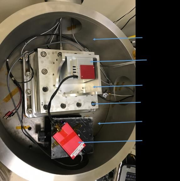
Sternberg, D. C. et al.

     Most small spacecraft flown thus far have operated      Moon, including three gravity-assist lunar flybys. Af-
in Low Earth Orbit (LEO), largely because deep space         ter six months, LF is inserted into a lunar near-rectilin-
operation is more costly than LEO missions due to a          ear halo orbit (NRHO), achieving a perilune distance
demand for more sophisticated and often more auton-          of approximately 15 km above the lunar south pole. At
omous designs that can accommodate limited telecom-          perilune, four near-infrared lasers will be pointed to-
munication opportunities. The Jet Propulsion Labora-         ward the permanently shadowed craters for water ice
tory (JPL) has been at the forefront of developing deep      detection (Imken, 2016). Overall, the spacecraft is re-
space SmallSats with four deep space missions follow-        quired to point within one degree of a commanded at-
ing NASA’s CubeSat Launch Initiative (NASA Cu-               titude, and perform momentum management thruster
beSat Launch Initiative, 2016). These JPL small satel-       firings on an as-needed basis throughout the mission.
lites have been called CubeSats, a name given because        The Science Phase of the mission is two months long
of the fundamental spacecraft layout consisting of an        (right side, Figure 1). In this figure, yellow indicates
arrangement of 10×10×10 cm3 units. A major chal-             the desired elliptical trajectory, while green overlay in-
lenge to deep space exploration is that the space envi-      dicates periods of communications with the Deep
ronment is different for each mission, requiring testing     Space Network (DSN), red overlay indicates periods
campaigns that consist of both standard and mission-         for thruster-based orbit maintenance, dark grey indi-
specific tests. The process governing the test cam-          cates eclipse periods, and light grey indicates the pri-
paigns described in this paper applies to future JPL         mary science pass sector. The detailed scientific mis-
CubeSats, regardless of operational environment. The         sion, payload design, and flight avionics for LF have
testing is a key factor in determining the net mission       been discussed in Cohen (2015) and Imken (2016 and
cost, since the number and depth of these tests add          2017).
both time and monetary costs to flight projects. Vali-            One of the most critical systems of the LF mission
dation and verification tests are critical, since once       is the GNC system. Its main functions are to transport
launched, there are limited opportunities for in-flight      the spacecraft from Earth to the Moon, and once in lu-
adjustments, and even small anomalies may lead to            nar orbit, to point the payload instrument toward the
mission failure. Rigorous testing requires extensive         center of the Moon (nadir-pointing) for scientific
planning and costs, which can place a significant bur-       measurements. The Lunar Flashlight GNC architec-
den on small CubeSat budgets.                                ture was developed following the approach of the In-
     The JPL Lunar Flashlight (LF) CubeSat is a 6U,          terplanetary Nano-Spacecraft Pathfinder In Relevant
14 kg spacecraft planned to be launched as a secondary       Environment (INSPIRE) mission (NASA Jet Propul-
payload among twelve other CubeSats on the Space             sion Laboratory INSPIRE, 2018) and Mars Cube One
Launch System’s (SLS) Exploration Mission-1 (EM-             (MarCO) (NASA Jet Propulsion Laboratory MarCO,
1) flight and will map the lunar south pole for volatiles,   2018; Klesh, 2018) using a COTS integrated GNC sys-
i.e., surface water ice (Cohen, 2015). Recent robotic        tem, XACT by Blue Canyon Technology. A new reac-
mission data (LRO Diviner, LOLA, LAMP, Mini RF,              tion wheel assembly (RWA) was developed with 50
and LCROSS) strongly suggest the presence of ice de-         mNms momentum capacity by Blue Canyon Technol-
posits in permanently shadowed craters of the moon.          ogies (BCT) to meet the LF requirement of post-sepa-
Therefore, the goal of LF is to find potential water ice     ration detumbling at up to 10 deg/s after deployment
hidden in these permanently shadowed regions (PSR).          from the launch vehicle (Blue Canyon Technologies
This mission also demonstrates several technological         Attitude Control Systems, 2018). This new reaction
firsts, including being the first planetary CubeSat mis-     wheel was incorporated into the BCT XACT inte-
sion to use green propulsion and the first CubeSat mis-      grated attitude control system to create the XACT-50
sion to use lasers to search for water ice (NASA Jet         unit.
Propulsion Laboratory Lunar Flashlight, 2018; Imken,
2016). After deployment from the launch vehicle, LF
will follow a 190-day low-energy orbit transfer to the

Copyright © A. Deepak Publishing. All rights reserved.                                       JoSS, Vol. 10, No. 1, p. 960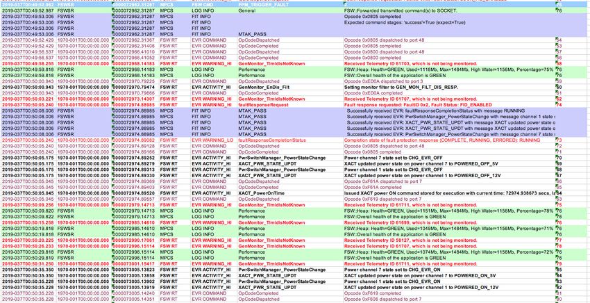
Pre-Launch Testing of the Lunar Flashlight (LF) CubeSat GNC System

                 Figure 1. Lunar Flashlight mission overview.

    LF was the first CubeSat at JPL to undergo a large-               handling (C&DH) systems. The XACT-50 FM later
spacecraft-style formal testing process, which de-                    repeated a similar validation process.
manded the creation of test plans, procedures, and reg-                    In this paper, a follow-on to Lai (2018 and 2020),
ularly held test data reviews. Due to cost and time con-              the following topics are presented: a summary of the
straints, prior JPL CubeSats underwent GNC verifica-                  GNC design, the hardware qualification tests, func-
tion and validation processes that were more scaled                   tional performance assessment tests, reaction wheel
down from those for larger missions, as described in                  jitter characterization testing (Shields, 2017), mission
Pong (2019). The GNC system in particular for LF un-                  scenario tests, ATB validation, and lessons learned.
derwent a comprehensive set of functional and perfor-                 Each of these topics is addressed in detail in the fol-
mance tests on both engineering and flight units prior                lowing sections, with particular attention given to the
to integration with the rest of the spacecraft. This test-            testing process and results of the flight unit testing.
ing effort involved the XACT-50 engineering design                    Additionally, the current paper provides a brief intro-
unit (EDU) and flight model (FM) conducted at JPL’s                   duction to the interface between the XACT-50 and the
Small Satellite Dynamics Testbed (SSDT) facility                      spacecraft C&DH system and the ground commanding
(Sternberg, 2018), as well as in an Avionics Test Bed                 system. The paper will focus primarily on the XACT-
(ATB). The EDU went through hardware and software                     50 unit rather than the interfaces with the other subsys-
validation tests such as phasing testing on the reaction              tems, because it serves as the core of the GNC system,
wheel assembly (RWA), inertial measurement unit                       responsible for controlling both its own actuators and
(IMU), stellar reference unit (SRU), and coarse sun                   sensors, as well as commanding the propulsion sys-
sensors (CSS), RWA jitter testing, and nadir-point-                   tem.
ing/sun-pointing tests at SSDT. Afterwards, the EDU
was delivered to the ATB to verify the communication
between GNC, propulsion, and command and data

Copyright © A. Deepak Publishing. All rights reserved.                                                 JoSS, Vol. 10, No. 1, p. 961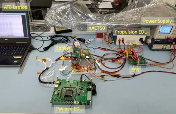
Sternberg, D. C. et al.

    LF Guidance, Navigation, and Control System              in SFM, performing sun search autonomously until the
                                                             spacecraft reaches the sun-pointing attitude that points
    The LF GNC system is summarized in this section.         the spacecraft +Z axis toward the Sun for maximum
For details, readers are referred to Lai (2018 and           power available from the solar arrays. In this mode,
2020). The LF spacecraft layout is shown in Figure 2.        the CSS and IMU are used to establish spacecraft atti-
The XACT-50 unit is the core of LF GNC system. It            tude, while the RWAs orient the spacecraft to point to-
consists of an SRU, IMU, and three RWAs, along with          wards the Sun. A 0.2 deg/sec rotisserie spin is com-
the GNC flight software (FSW) within one box                 manded along the sun vector to increase spacecraft sta-
(shown in Figure 3). Unlike ASTERIA or MarCO                 bility, improve thermal balancing, and help balance
(Sternberg, 2019), LF has four BCT-designed CSS to           momentum build-up.
provide close to 4π steradian coverage: one sensor is             While in SFM, the spacecraft can be commanded
mounted to the body +/-Y and +/-Z axes. These CSS            to enter FPM for cruise and scientific activities. In this
are mounted separately, but connect electronically to        mode, the SRU and IMU determine spacecraft attitude
the XACT-50.                                                 with measured data processed by a Kalman filter.
                                                             Upon entering this mode, GNC FSW autonomously
                                                             performs a lost-in-space star identification algorithm
                                                             within a few seconds. Once the correct attitude is de-
                                                             termined, the FSW then changes to the tracking mode.
                                                             When the SRU’s field of view (FOV) is obstructed or
                                                             intruded by a bright object, the IMU is used to propa-
                                                             gate attitude until the SRU can regain attitude
                                                             knowledge. In nominal operation, the RWAs are also
                                                             used for attitude control in FPM.
                                                                  The LF spacecraft does not have direct command
                                                             or telemetry lines to its propulsion system, though it
                                                             provides 5 V and 12 V power directly to the propulsion
                                                             system. All the propulsion system commands and te-
Figure 2. Final spacecraft layout and coordination system.   lemetry go through the XACT-50 unit. Therefore, it is
                                                             critical to verify the proper interface connectivity be-
                                                             tween the spacecraft computer, the XACT-50, and the
                                                             propulsion unit early in the spacecraft development
                                                             stage. To verify this interface, an EDU was used for
                                                             testing at BCT during the XACT-50 development and
                                                             delivered to JPL for use in the ATB. This ATB testing
                                                             is described in a later section of this paper. There was
                                                             no flight-like testing of the propulsion system once it
                                                             was integrated with the rest of the spacecraft. Instead,
                                                             a set of simulations was performed to assess the per-
                                                             formance of the propulsion system.
                                                                  The CAD model of the propulsion system is shown
                                                             in Figure 4, including four thrusters and a propellant
Figure 3. XACT-50 integrated GNC system.
                                                             tank. The four thrusters are canted at 12° for three-di-
    The LF GNC FSW has two control modes, Safe               mensional control, and are used for dumping accumu-
Mode (SFM), pointing the solar panels to the Sun; and        lated RWA momentum and performing ΔV maneu-
Fine-Pointing Mode (FPM), which points the space-            vers. Each thruster is capable of operating in continu-
craft in a commanded attitude. The system powers on          ous burn and pulsed modes.

Copyright © A. Deepak Publishing. All rights reserved.                                       JoSS, Vol. 10, No. 1, p. 962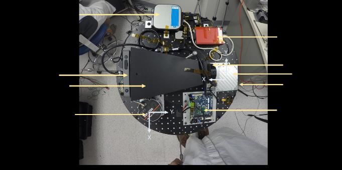
Pre-Launch Testing of the Lunar Flashlight (LF) CubeSat GNC System

                                                                          assurance that both units would function as expected,
                                                                          with the specific tests on each unit tailored to the hard-
                                                                          ware contained within each XACT-50 unit. Phasing
                                                                          tests provide assurance that the hardware and software
                                                                          both are able to operate and are able to match the con-
                                                                          ventions for coordinate frames defined by the LF pro-
                                                                          ject. Software mode tests were included to build upon
                                                                          the phasing tests, as these closed-loop tests assess the
                                                                          functionality of the controllers themselves. Lastly, the
                                                                          jitter and imbalance testing was performed to assess
Figure 4. Bottom view of spacecraft showing propulsion module and
                                                                          the one of the dominant noise sources that will exist
sun sensor.                                                               onboard the spacecraft. Unlike larger missions, the LF
                                                                          testing was able to be performed with the entire atti-
                                                                          tude control system mounted to an environmental sim-
    GNC Hardware Validation Test at Small Satel-                          ulator in a dynamically relevant physical environment,
    lite Dynamics Testbed                                                 entirely separate from the rest of the spacecraft. Addi-
                                                                          tionally, because the XACT-50 is a complete vendor-
3.1. Creating a Test Sequence for the LF GNC                              supplied unit, all attitude determination and control
     System                                                               software had already been loaded onto the hardware
                                                                          and tested by the vendor. Consequently, the testing
    LF GNC testing used many of the testing philoso-                      performed at JPL was of a system that had already un-
phies used by larger spacecraft that are described in                     dergone basic testing by the vendor.
Pong (2019). Unlike on the MarCO and ASTERIA                                   The EDU XACT-50 and FM XACT-50 units have
missions, for example, the LF GNC testing process                         different GNC hardware components. While they have
was designed to include dynamic tests instead of just                     the same internal software structure, the FSW deliv-
static tests. Lessons learned from both large and small                   ered with the EDU XACT-50 was not the final soft-
missions were applied in the development of the LF                        ware version, which had not yet been completed.
GNC testing process.                                                      While the FM XACT-50 is a complete unit with all of
    When the XACT-50 was delivered to JPL, it was                         the flight sensors and actuators, including four CSS for
necessary to test the unit before ATB integration. This                   mounting to the exterior of the spacecraft (each CSS
testing ensured that it met the functional requirements                   consists of four diodes each), the EDU XACT-50 does
for its successful operation within the spacecraft and                    not have the SRU and has only one CSS. The software
that its key functions were exercised in a relevant en-                   difference between the two units is centered on a set
vironment. Three sets of tests were performed on the                      of physical property information that is stored in
EDU and FM XACT-50 units as listed in Table 1, to                         memory tables within the XACT-50 units; because
provide an assessment of the functionality of each ma-                    these tests are not performance tests, this software dif-
jor element of the XACT-50. The three sets of tests,                      ference does not play a role in assessing the function-
grouped by the color-coding, were scoped to provide                       ality of the hardware and two main software modes.
                                                                               The green-highlighted tests in Table 1 were per-
 Table 1. XACT-50 Hardware Test Matrix
                                                                          formed together as the first set to assess the EDU’s
                                                                          functionality through: a RWA phasing test (determin-
                                                                          ing that commands to the reaction wheels yield the ex-
                                                                          pected rotation directions), an IMU phasing test (de-
                                                                          termining that the estimated rotations are in the ex-
                                                                          pected directions and at the commanded rates), and a
                                                                          CSS phasing test (to ensure the diode counts from a

Copyright © A. Deepak Publishing. All rights reserved.                                                     JoSS, Vol. 10, No. 1, p. 963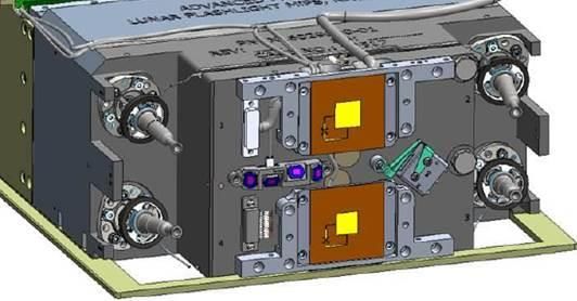
Sternberg, D. C. et al.

sun simulator match expectations). Additionally, this       was a test procedure document. Developed after exten-
set included a fine-pointing operation test (to ensure      sive table-top planning and a test plan review with a
that the XACT-50 can attempt to maintain a specific         particular focus on ensuring a complete functional as-
spacecraft attitude), and a sun-pointing operation test     sessment of each hardware element and software
(to ensure that the XACT-50 can attempt to find and         mode, a test procedure was prepared to span a set of
point spacecraft to the sun simulator).                     related tests (such as all EDU tests being aggregated
    The same set of tests was then performed on the         into one test procedure, since they were all performed
FM XACT-50 (the yellow-highlighted set in Table 1),         serially and in one testing phase). While other JPL Cu-
though a test of the SRU phasing (to determine if the       beSat projects had test procedure documents as well,
SRU could identify the rate and direction of star field     the LF procedures were the most thoroughly vetted to
motions) was added to test this sensor. Importantly,        date. Dedicated, independent reviews were performed
that the FPM performance will be different between          by project and line management as well as project
the EDU and FM sets of testing campaigns: the lack of       quality assurance prior to a formal procedure review.
SRU in the EDU limits the fine-pointing test because        A final test readiness review was also performed prior
without the external reference sensor, it cannot com-       to each test. No such process existed at JPL for sub-
pensate for gyroscopic drift.                               system testing on CubeSat missions prior to LF.
    Lastly, a RWA jitter test was performed on the               For LF, the result of the preliminary work for each
EDU only to characterize this newly developed 50            test procedure was a document that contained all of the
mNm RWA (brown test in Table 1). It therefore pro-          information necessary for an engineer not on the pro-
vided a first order assessment of the jitter that will be   ject to understand the scope and technical justification
seen on flight, since the FM and EDU XACT-50 units          for each test, as well as to be able to complete each
are not structurally identical. Unlike many larger mis-     step in the procedure without any additional training.
sions, a detailed jitter model is typically not available   To reach this level of procedural detail, the test proce-
for CubeSats with limited budget for use in determin-       dures include: detailed photos and drawings of the
ing a quantifiable effect on the science return from the    hardware in the to-be-tested configuration with in-
spacecraft’s instrumentation.                               structions on how to assemble that configuration; sets
    The aforementioned set of tests is described in the     of test objectives with pass/fail criteria in relation to
rest of this section. Section 3.2 describes the common      project requirements and telemetry to be analyzed;
set of documentation that accompanies each test as          handling and storage requirements; necessary training
part of the overall rigorous testing scheme used by the     for all operators; step-by-step procedures for running
LF project, while Section 3.3 describes the testing ven-    each test; and a set of unplanned test termination and
ues used for each of the tests. Section 3.4 describes       troubleshooting steps for the operator to use in the
why the LF FM XACT-50 requires different test con-          event that a test needs to be aborted. All of this infor-
figurations than the EDU. Section 3.5 provides more         mation provides the test conductor sufficient back-
details about the tests conducted on the EDU, while         ground and operational guidance to perform each test
Section 3.6 provides the details for the EDU jitter tests   safely while ensuring that the test data products are ac-
and Section 3.7 provides data from the FM tests.            quired as expected.
                                                                 After each set of tests were completed, two key
3.2. Documentation and Reviews for Each Test                documents were created. The first was a review
                                                            presentation describing the analyzed test results and
    The LF GNC system testing process was the first         any anomalies that were encountered during the test-
effort at JPL to apply a large-scale spacecraft GNC ap-     ing. This test result review served as the main venue
proach to how the test planning, documentation, and         for presenting the results of each test and evaluating
reviews were conducted for the development of a Cu-         the success of the testing, the current state of the pro-
beSat project’s GNC system. One of the most critical        ject, and any issues that arose with the test equipment.
documents that was developed for each type of test          All issues were also reported, as is standard for all JPL

Copyright © A. Deepak Publishing. All rights reserved.                                     JoSS, Vol. 10, No. 1, p. 964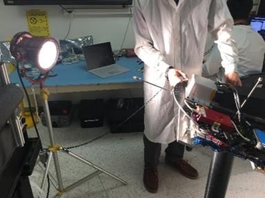
Pre-Launch Testing of the Lunar Flashlight (LF) CubeSat GNC System

projects, in a dedicated problem reporting system tool             The SSDT testing of LF’s EDU and FM XACT-50
so that root causes can be tracked and all affiliated doc-     units was performed on the spherical air bearing to as-
uments surrounding the issue are saved for access by           sess the XACTs’ performance on all three rotational
any future user of the hardware or software in ques-           degrees of freedom. The SSDT’s spherical air bearing
tion. Further, a test report document was provided to          can accommodate a wide range of test payloads, and
both project and line management with a set of lessons         was configured to provide a neutrally stable platform
learned was prepared to capture operational consider-          capable of powering the XACT-50 unit under test,
ations for testing and integrating the unit under test and     send commands, log telemetry, and provide sensor in-
ground support equipment later in the project develop-         puts as necessary without any cables or tethers con-
ment cycle. The data from these tests was not used for         straining the motion of the hardware. Coarse and fine
performance validation, but the assurance that each el-        balance weights were used to achieve a minimal sepa-
ement functions as expected is invaluable throughout           ration between the center of mass and center of rota-
the subsequent requirement verification and validation         tion of the air bearing, since any offset leads to gravity-
process. The data and as-run procedures are saved in           induced disturbance torques that would not be present
the project’s data repository for access by anyone on          in the space environment.
the project, and like all JPL projects, any unexpected             Jitter testing was performed at night in a basement
results are saved in a dedicated JPL system for access         laboratory at JPL to minimize the impact from sources
by other projects that use similar hardware, software,         of disturbance vibration from the environment, such as
or processes. The project’s systems engineers are able         elevator or car motion. This testing was performed on
to complete concept of operations designs, mission             a large isolator upon which the XACT-50 EDU was
timeline analyses, and maneuver sequences, amongst             mounted. After sending a range of known RWA speed,
others, using the outputs from these tests as well.            commands, the resulting vibrations were then rec-
                                                               orded.
3.3. Testing Venues                                                Connected to the XACT-50 units for all ground
                                                               testing was a separate unit from BCT called the Real-
     All of the acceptance and functionality tests except      time Dynamics Processor (RDP). The RDP acts both
for the RWA jitter test were performed in the SSDT.            as an environmental simulator that can inject simu-
The SSDT was founded at JPL in 2014 to reduce risks            lated sensor measurements based on a real-time simu-
associated with attitude control and to centralize the         lation of the spacecraft’s position and attitude over
testing infrastructure needs for small satellites. The fa-     time, while also capturing telemetry and allowing the
cility maintains the spacecraft hardware and testing           user to send commands to the unit. The RDP therefore
environments necessary to support dynamics testing             was instrumental in the testing process, since it al-
with a variety of SmallSat sensors, actuators, and soft-       lowed the sensors and actuators to respond as if they
ware. In particular, the SSDT has two separate air             were in the flight environment.
bearing environments: a spherical air bearing with
three rotational degrees of freedom (DOFs), and a pla-         3.4. Test Setup for Engineering Design Unit
nar air bearing with one rotational and two transla-                Testing
tional degrees of freedom (Sternberg, 2018). The pla-
nar air bearing can operate either on a 0.6 m × 0.6 m              This section describes the test setup used for the
granite table in the SSDT or the much larger (7.3 m x          LF EDU hardware in the SSDT, with the EDU testing
8.5 m) flat floor of JPL’s Formation Control Testbed           process providing an example of how the test setup
(FCT) (Scharf et al., Parts I and II, 2010). The facility      supported the overall LF testing campaign. The EDU
space in the SSDT allows other equipment to be in-             testing was designed for generating and proofing the
cluded as sensors and stimulators as well. The LF pro-         procedures required for testing the FM, and the overall
ject made use of a 1kW lamp as a sun simulator, for            set of EDU tests proceeded as planned, with test plan
example.

Copyright © A. Deepak Publishing. All rights reserved.                                          JoSS, Vol. 10, No. 1, p. 965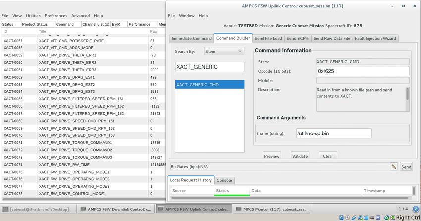
Sternberg, D. C. et al.

and procedure improvements folded into the FM test-              The star field is computed using the current orienta-
ing process. Importantly, no tests in this section di-          tion of the XACT-50 unit as determined by a separate
rectly verified the mission’s GNC requirements.                 ground truth gyroscope; the SFS computer determines
    The test configuration on the SSDT spherical air            the correct star field to be displayed for a given space-
bearing is shown in Figure 5, with the bulk of the setup        craft attitude. Filipe (2017) provides a much more in-
being reused for FM testing. The solar simulator shin-          depth assessment of the performance capabilities of
ing onto the air bearing is shown in Figure 6; at this          the SFS and how the system functions as ground test
distance, the CSS are able to identify the lamp as the          equipment; importantly, the high-definition screen is
dominant illumination source without risking thermal            able to produce brightness and centroid data graph-
damage from the 1 kW halogen lamp. Further, a Star              ically to a level of accuracy such that the XACT-50’s
Field Simulator (SFS) developed at the SSDT was in-             algorithms are the limiting factor in achieving fine-
corporated into the testing (Filipe, 2017). The SFS dis-        pointing. A baffle is used to prevent stray light from
plays an image of a star field on a small high-definition       entering the XACT-50’s optics, and a collimator lens
screen, with the image being sent via HDMI cable                is used to ensure that the incident light from the SRU
from a dedicated SFS computer.                                  behaves as if the XACT-50 were viewing far away
                                                                stars. This complete setup is shown in Figure 7. Alt-
                                                                hough the SFS was not used as part of the control loop
                                                                for EDU testing because of there not being a SRU in-
                                                                side the EDU XACT-50, the hardware was included in
                                                                the test configuration to maintain close mass property
                                                                commonality with the FM test configuration. Instead
                                                                of the SFS for the EDU tests, the RDP was used to
                                                                generate attitude knowledge for XACT-50 FSW dur-
                                                                ing the FPM test, since the RDP provided simulated
                                                                SRU data.

Figure 5. Top-down view of SSDT spherical air bearing system.

                                                                Figure 7. SSDT star field simulator, with screen, baffle, and collima-
                                                                tor lens as black structures to the right of the silver XACT-50 and red
Figure 6. SSDT solar simulator setup.                           RDP.

Copyright © A. Deepak Publishing. All rights reserved.                                                  JoSS, Vol. 10, No. 1, p. 966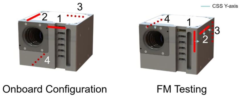
Pre-Launch Testing of the Lunar Flashlight (LF) CubeSat GNC System

    The overall electrical integration that was used for                   1760 gyroscope, Atlas single board computer, and the
the EDU and FM testing is shown in Figure 8, though                        SFS screen, hood, and lens assembly. A separate lap-
there are some differences between the connections, as                     top is used for designing the SFS initialization files;
described in Section 3.5. The XACT-50 unit, with its                       this laptop is not mounted to the spherical air bearing
connected CSS, interfaces with a single connection to                      for testing. All of the cabling was tightly secured to
another device. For this test configuration, the other                     prevent center-of-mass changes during dynamic mo-
device is the RDP, which receives power from the                           tions, which would create unwanted disturbance tor-
SSDT spherical air bearing’s power distribution unit                       ques on the system. At the start of the testing process,
(PDU), which itself draws from an on-board Li-Ion                          coarse balancing with large masses were attached to
battery pack. The EDU does not have connections for                        the spherical air bearing, and trim masses of washers
the second through the fourth CSS. Data from the RDP                       on threaded rods were used to fine balance the com-
is sent over an Ethernet connection to a Quantum Plus                      plete system before each test in the event that cables
computer, which serves as an on-board telemetry and                        shifted.
commanding computer. The Quantum Plus is a Win-
dows 10 computer that runs the data-logging software                       3.5. Unique Flight Model Test Configurations
and allows for commands to be sent to the XACT-50
from the SSDT’s ground station computer. The PDU                               The FM testing was designed to demonstrate the
on the spherical air bearing also powers the SFS sys-                      functionality of the hardware and software in the de-
tem, which relies on the spherical air bearing’s KVH                       livered flight hardware without making performance

          Figure 8. Electrical connection diagram in the JPL Small Satellite Dynamics Testbed.

Copyright © A. Deepak Publishing. All rights reserved.                                                     JoSS, Vol. 10, No. 1, p. 967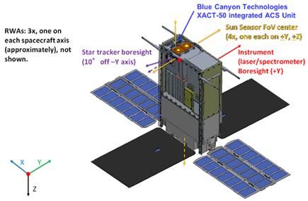
Sternberg, D. C. et al.

specification assessments, and was based on process                          3.6. Reaction Wheel Jitter Testing
and procedures developed in the EDU tests. This test-
ing differed from the EDU testing in that the SRU was                             The RW jitter testing was designed to characterize
used in concert with the SFS. Again, no tests directly                       this newly developed 50 mNm RWA following the
verified the GNC requirements of the LF mission,                             proven JPL in-house methodology (Shields, 2017) and
since the controllers were not modified to account for                       conduct performance assessments of the vibration cre-
the difference in mass properties of the spherical air                       ated by the spinning wheels (one wheel per axis) at the
bearing as compared to the LF spacecraft. Conse-                             integrated GNC system level. No tests directly verified
quently, the performance of the controllers will not                         the GNC requirements of the LF mission, though the
perform in the exact manner as if they were controlling                      results helped inform the method of operating the
the spacecraft.                                                              spacecraft. The testing was performed on the Kistler
    Figure 2 showed earlier in this text that the four                       table as shown in Figure 10, and it obtained the data to
CSS are placed on different faces of the spacecraft to                       create a model of the jitter induced by the RWAs spin-
provide wide coverage and minimize overlapping                               ning in the range of -6,000 rpm to +6,000 rpm. This
fields of view. The relative configuration between the                       process produced waterfall jitter plots for each axis’
XACT and the CSS is captured in software, but chal-                          force and moment jitter components. These models,
lenges the physical limitations of the ground testbed.                       however, are based on the EDU wheels within the
To accommodate the additional CSS in the test envi-                          EDU chassis. The EDU XACT-50 was used for this
ronment, the four total FM CSS were rotated 90 deg as                        jitter testing to reduce the number of wheel actuations
shown in Figure 9, such that no sensors were located                         on the flight units. This difference between the test ar-
on the bottom of the XACT-50 unit. This change ena-                          ticle and the flight unit prevents a direct use of the ac-
bled the CSS to be entirely above the top surface of the                     quired data for predicting flight performance, but it
spherical air bearing, thereby allowing the sun simula-                      provides a qualitative assessment of possible modes
tor lamp to shine directly onto each sensor. Changing                        and effects that may be seen in space.
the software representation in accordance with the
physical rotation required a change to the on-board ta-                      3.7. Test Results from FM Testing
ble within the XACT-50’s memory that was not per-                              This section includes example test results from the
manently stored (only stored in volatile memory), so                         FM set of tests. These results show the FM behavior
as to avoid permanently writing the testing configura-
tion to memory.

       Figure 9. Rotated sun sensor positions to enable FM ground testing.

Copyright © A. Deepak Publishing. All rights reserved.                                                       JoSS, Vol. 10, No. 1, p. 968
Pre-Launch Testing of the Lunar Flashlight (LF) CubeSat GNC System
Figure 11. CSS 4 diode count history during sun sensor phasing test.
after 60 seconds into the test being higher than the am-
bient light condition. The high count levels between
approximately 35 and 42 seconds occur because of the
CSS being pointed nearly directly to the sun simulator.
The peak diode count is roughly half of the value ex-
pected for 1AU distances, highlighting the need to ad-
Figure10. Top-down view of jitter testing setup. just the diode threshold during ground testing for what
is deemed a valid CSS measurement. This test there-
operating on the SSDT’s spherical air bearing with dif- fore shows the ability of the CSS to output counts at
ferent mass properties, without changes to the XACT- the expected levels for ambient room conditions and
50’s core control or estimation software, and therefore when exposed to a sun simulator lamp. Further, it jus-
are not directly representative of the expected flight tifies the need for strong light sources to be used in
performance. such tests, as even the lamp used here resulted in
counts half of what the CSS is capable of measuring.
3.7.1. CSS Phasing Test
3.7.2. SRU Phasing Test
Figure 11 shows the diode counts during a CSS
phasing test that focused on the fourth CSS, corre- Figure 12 shows the results of the SRU phasing
sponding to diode numbers 13 through 16, as indicated test when the spherical air bearing was not floating so
in the figure legend. Over the course of the test, the
spherical air bearing was rotated manually to orient the
fourth CSS to the sun simulator, which explains the
uneven nature of the response curves during the first
35 seconds. Additionally, the manual motion is evi-
dent in the variability of the CSS counts during the 35
sec to 42 sec period when the CSS was pointed toward
the sun simulator. The ambient light in the room re-
sults in a low level of counts (as shown between ap-
proximately 45 and 55 seconds), though the diodes
within the CSS unit are able to pick up some stray light
from the sun simulator lamp even when not angled di-
rectly toward the sun simulator. This effect is visible
by the count levels before 30 seconds into the test and Figure 12. SRU phasing attitude and rate history.
Copyright © A. Deepak Publishing. All rights reserved. JoSS, Vol. 10, No. 1, p. 969Sternberg, D. C. et al.
that it was fixed in place. The SFS was commanded to The test of the sun-pointing operation was per-
slew about all three axes in a one-at-a-time order: roll, formed by manually moving the spherical air bearing
pitch, and yaw. Consequently, only the simulated star to an off-sun simulator attitude and allowing the inter-
field was free to move. Each axis was commanded to nal XACT-50 algorithms to slew the spacecraft until
rotate first with an acceleration of 0.1 deg/s2 until the sun simulator was found by one of the CSS. There-
reaching 1 deg/s, at which point the star field was held after, the XACT-50 pointed the spacecraft +X axis to
still with no rate. After ten seconds of this static con- the sun simulator despite disturbance torques, most
dition, the acceleration was reversed to arrive at the notably the gravity torque, because of a nonzero offset
same angle as the initial condition. As a result, the of the center of mass to the center of rotation. Figure
rates all return to static after each axis’ test, while the 13 shows the manual motion at the start of the test, as
attitude angle returns to the initial value prior to the well as the result of the XACT-50 slewing to maintain
commanded star field slewing. The SRU attitude angle the desired pointing vector with the red curve (y-axis)
top graph shows the five degree change in attitude that pointed to the sun, with the x and z axes pointed or-
was attained, while the lower rate estimate from the thogonally to the sunline. The circles on the right
SRU shows the triangular slew periods, where the graph edge show the desired locations for each curve,
ramp rate is determined by the commanded star field with each circle’s color matching that of the corre-
rate of change. Throughout the duration of this test, the sponding data curve. Because the inertia properties
star tracker was able to track the star field for nearly saved within the XACT-50 are different from those of
the full duration. A small drop near the 110 sec mark the spherical air bearing, the system exhibits a control
shows a short period where the star tracker was unable behavior with oscillations that are larger than expected
to determine its orientation, resulting in no angle being once in flight. The comparatively large gravity dis-
reported. Such a short drop, likely a random glitch or turbance torques combined with the difference in iner-
stray light effect in the measurement, is not significant, tial properties lead to the residual error shown in the
and such a drop once in flight will not affect the space- plot at the end of the test. Despite these oscillations
craft’s ability to perform its mission. Additionally, the and the gravity disturbance torque, the XACT-50 was
test reveals information about the noise that can be ex- able to identify the sun, slew to the correct attitude,
pected in the tracker’s attitude estimate, since the third and generally maintain pointing for over 100 seconds.
axis exhibits increased noise compared to the other Therefore, the phasing of the sensors was demon-
two. This test therefore demonstrates that the SRU was strated in concert, while demonstrating a basic func-
able to identify correctly the axes and direction of tionality of the sun-pointing operation.
travel, completing the objective for the phasing test.
The SRU coordinate frame is as expected by the FSW
and telemetry system, so it may be used in further,
more complex tests.
3.7.3. Safe Mode Test
The sun-pointing operation does not use the SRU
attitude estimates in determining the location of the
sun, though the SRU remains powered on. The CSS
provide measures of incident sunlight as a number of
counts per diode, and the IMU rate is used to track the
spacecraft attitude. Therefore, a phasing test of the
sun-pointing operation tests the ability for the CSS and
the IMU to command the three reaction wheels to find
and track the sun. Figure 13. Sun-pointing operation, sun vector in body frame.
Copyright © A. Deepak Publishing. All rights reserved. JoSS, Vol. 10, No. 1, p. 970Pre-Launch Testing of the Lunar Flashlight (LF) CubeSat GNC System
3.7.4. Fine-Pointing Mode Test
Figures 14 and 15 show data from a fine-pointing
operation test. In this test, the SRU was tested with the
SFS providing closed-loop star fields based on the ro-
tation of the spherical air bearing. The goal of the fine-
pointing test was to determine the qualitative ability of
the XACT-50 to maintain its attitude despite external
disturbances, such as the gravity-based torque. The
XACT-50 SRU initializes to the unit quaternion [0 0 0
1], with scalar last; if the SRU estimate of the attitude
remains at this value, then the SRU does not have a
valid estimate of the spacecraft attitude.
Figure 14 shows two circled regions showing rep-
resentative regions where the SRU was able to track
the star field from the SFS (indicated by the quaternion
elements each becoming approximately 0.5), and Figure 14. Fine-pointing operation tracker attitude quaternion (scalar
last).
where the SRU was not able to lock onto the star field
(where the SRU estimate is the initialization quater-
nion). The air bearing was free to rotate throughout
this test, with the reaction wheels controlling the plat-
form motion based on what the gyroscopes and SRU
measured. This figure shows that the SRU was able to
maintain lock for approximately 50% of the test, likely
owing to a combination of factors including spherical
air bearing oscillations and unintended motions or not
fully collimated light entering the SRU optics stem-
ming from SFS positioning errors. Subsequent testing
of the SRU in the same test conditions as what was
performed for MarCO’s pre-delivery checkout in a
static configuration with a programmed star field his-
tory resulted in similar performance to MarCO, with
almost no loss of lock. Because of this result, the LF Figure 15. Fine-pointing operation test reaction wheel speed and body
quaternion (inertial frame).
project did not work to extract the star fields from the
loss of lock windows and test for lock when the plat-
form was static. Because no other XACT unit has ex- and gyroscope. This set of RWA speeds shows that the
hibited this kind of tracking lock behavior (because second wheel speed increased significantly more than
this test was not performed on any other XACT unit the other wheel speeds, owing to the offset center of
for any other mission), the project deemed the test in- mass of the spherical air bearing being aligned mostly
formative for operations considerations, and the pro- with that axis. Despite this torque, the achieved qua-
ject is tracking the star tracker performance as an ac- ternion is nearly unchanged, demonstrating that the
ceptable project risk. RWAs were able to compensate for the torque by in-
Figure 15 shows the RWA speeds and the corre- creasing their stored momentum. The smooth quater-
sponding quaternion history, with ‘Q Body wrt ECI’ nion history also demonstrates that the SRU moving in
being the attitude estimate telemetry output by the and out of lock does not significantly affect the ability
XACT-50 using measurements from the star tracker of the XACT-50 to estimate its attitude; over these
Copyright © A. Deepak Publishing. All rights reserved. JoSS, Vol. 10, No. 1, p. 971Sternberg, D. C. et al.
shorter periods, the onboard IMU is sufficient for of operation for the wheel, while the amplitude shows
providing rotational rate estimates. The small reaction the force that is created from the spinning wheel. To
wheel disturbances around the 250 sec and 300 sec acquire the jitter data, wheels were spun over the full
points are likely caused by the attitude estimate being range of speeds from -6,000 to 6,000 rpm in steps of
improved from a SRU measurement update or from 200 rpm, with a hold of 60 sec at each speed. There is
the controller compensating for the larger platform in- a steady increase in the primary vibration mode
ertia. Similarly, the roll off in wheel speed at the end through 100 Hz peaking at approximately 0.5N at 100
of the test is likely due to a test engineer holding the Hz, as this frequency corresponds to the 6,000 rpm
spherical air bearing to stop the test shortly before the maximum speed of the reaction wheels. There are
telemetry finished logging. larger amplitude peaks throughout the frequency
range, however, which correspond to additional jitter
3.7.5. Reaction Wheel Jitter Test modes and harmonics approximately every 10 Hz.
These peaks are likely due to structural modes result-
The RWAs induce vibrations to the XACT-50 and ing from the mounting of the reaction wheel within the
spacecraft during their operation owing to imperfec- XACT-50 EDU chassis. This test, therefore, shows
tions in the mass distributions of the wheels and in the that the EDU exhibited a higher noise level in the
wheel mountings. These vibrations are a source of jit- 3,000-4,000 rpm range, with static and dynamic im-
ter within the spacecraft, and if incorrectly modelled, balances consistent with other, similar units that were
they can have significant deleterious impacts on space- tested previously for separate projects.
craft science outputs. Figure 16 shows an example of Testing the wheel vibration only on the EDU unit
the force amplitude spectrum data collected from the provides an overall assessment of the XACT-50 reac-
jitter testing in the X-axis. This spectrum shows the tion wheel characteristics without risking the potential
frequency range corresponding to the primary modes of incurring damage or wear to the FM wheels.
Figure 16. X-axis force amplitude spectrum during jitter testing.
Copyright © A. Deepak Publishing. All rights reserved. JoSS, Vol. 10, No. 1, p. 972Pre-Launch Testing of the Lunar Flashlight (LF) CubeSat GNC System
Though the FM wheels have better balance, the vibra- and unit idiosyncrasies encountered during the testing
tion characteristics are not expected to be significantly have been incorporated into future actionable steps for
different, since the wheel assemblies and most of the the project, including the beginning of a set of opera-
XACT-50 chassis is shared, though the missing com- tional rules once LF launches.
ponents in the EDU XACT-50 contribute to differing
overall structural properties. It is for this reason that GNC Integration with Avionics Testbed
the data obtained from the EDU testing cannot be di-
rectly applied to the FM wheels, though the data is use- 4.1. Hardware and Electrical Connections in ATB
ful in conducting overall systems engineering analyses
of the spacecraft. The waterfall plot data can be im- The ATB provides a ground testing platform for
ported into a simulation of the attitude control system software development, integration, and functional test-
for improved in-flight performance modelling. ing of the hardware and software elements, and as-
sessing the communication between each spacecraft
3.8. XACT-50 EDU and FM Testing Summary functional element. These benefits are possible be-
cause the ATB allows engineers to make flight-like
The testing of both the EDU and FM XACT-50 connections, as well as diagnostic connections. The
units provided several benefits to the LF mission cen- current LF ATB is set up to develop, test, and validate
tered on the desire to validate the functionality of the FSW that is planned to be used to operate the whole
GNC system’s hardware and software. The series of spacecraft via the C&DH (Sphinx) sub-system (Im-
initial EDU tests allowed the LF team to confirm the ken, 2017). It is also used to demonstrate the function-
basic operation of the provided XACT-50 software ality of each system when connected in a flight-like
and the coordinate frames that are used by the rest of manner to the Sphinx. Furthermore, it is critical for
the C&DH system. Furthermore, it validated the func- early detection of potential issues during integration of
tionality of the EDU so that it would be able to provide GNC and Propulsion systems from different vendors.
attitude determination and control functionality as part Importantly, the ATB is able to serve as the first step
of the ATB. Consequently, the EDU tests formed a toward full FM integration into the spacecraft, as many
baseline for the subsequent FM tests. of the connections made to the EDU in the ATB have
The FM tests ran with nearly identical test proce- corollaries when integrating the FM XACT-50 with
dures, and they were similarly able to demonstrate the the rest of LF’s flight hardware.
functionality of all sensors and actuators, as well as the The XACT-50 EDU was integrated with the rest
software on-board. The FM tests, being the only such of LF avionics and other system hardware including
tests on the unit prior to flight, allowed the LF team to the propulsion engineering unit in a flat-sat configura-
have a demonstrated set of capabilities on the ground tion to create the ATB as shown in Figure 17. The cur-
prior to full integration and in a relevant dynamics en- rent ATB has the following items connected with each
vironment. Ongoing EDU tests as part of the ATB take other: the Sphinx EDU, the Electrical Power System
the risks of software development for the C&DH sys- (EPS) EDU, the XACT-50 EDU, propulsion engineer-
tem away from the FM, while the jitter tests on the ing unit, and payload EDU.
EDU provide valuable disturbance data without sub- The XACT-50 EDU connected to the LF C&DH
jecting the FM to long duration dwells at high RWA system with a cable is nearly identical to the one that
speeds. The set of tests conducted on both the EDU will be used in flight, i.e., using a 31-pin nano-D con-
and FM using the SSDT facilities therefore span the nector that contains low voltage data signal lines
range of primary software modes and involved all sen- (LVDS) that are initially configured by pseudo-ran-
sors and actuators while following a more formal, in- dom binary sequences (PRBS). Additionally, the pro-
cremental testing process than prior JPL CubeSats and pulsion system EDU was connected both to the power
serve as standard process for future CubeSats at JPL. supply and to the XACT-50 EDU in a manner similar
Although out of the scope for this paper, anomalies to flight: the primary interface connector of the
Copyright © A. Deepak Publishing. All rights reserved. JoSS, Vol. 10, No. 1, p. 973Sternberg, D. C. et al.
wheel momentum dumping) or from C&DH com-
mands (such as a ground-based command for a trajec-
tory change maneuver). Commands to the propulsion
unit are routed through the XACT-50, and all teleme-
try from the propulsion unit is also routed through the
XACT-50 unit; this configuration allows the thrusters
to be controlled at a high level with some functions
handled entirely automatically by the XACT-50.
4.2. Ground Data System setup in ATB
The ground data system, namely Advanced Multi-
mission Operations System (AMMOS) Mission data
Figure 17. XACT-50 and propulsion EDUs integrated with ATB.
Processing and Control System (AMPCS) version 7.5,
XACT-50 breaks out to connect both to the propulsion is used in the ATB to provide data interface with the
and C&DH subsystems. The communication between Sphinx platform running FSW. AMPCS allows the op-
the XACT-50 and propulsion system units was tested erator to send commands and uplink files to FSW us-
to confirm their ability to send and receive data as part ing the uplink control window as displayed in Figure
of the ATB testing. Data flow from C&DH to the pro- 18. AMPCS has been used extensively for large mis-
pulsion unit goes through the XACT-50 data interface, sions at JPL, and has been successfully implemented
which acts as a pass-through for commands and telem- for the MarCO CubeSat mission.
etry to and from the propulsion unit.
The LVDS interface allows the C&DH system to
command the XACT-50 through a standard set of in-
terfaces that are identified in the interface control doc-
ument (ICD) provided by BCT. A sub-set of telemetry
map and commands contained within the XACT-50
ICD were used to define the spacecraft commands and
telemetry to interface with the XACT-50 unit. Also,
additional functionality was added to send any set-to-
generic data bytes to the XACT-50 unit and read the
entire telemetry map into a file on-board. Functional
testing was performed in the ATB to verify command-
ing and telemetry interface with the XACT-50 unit.
Once connected, the completed ATB setup enables
testers to develop the FSW used for commanding the
XACT-50 and processing its telemetry.
The first XACT-50 commands executed upon in-
tegration were to change the wheel operating mode to
IDLE. This process therefore confirmed that the te-
lemetry from the XACT-50 was able to be passed and Figure 18. AMPCS command builder tab in uplink control win-
interpreted by the C&DH system, as well as confirm- dow.
ing that the commands to the XACT-50 were being The command can be selected from the list dis-
generated, sent, and accepted appropriately. Com- played under Command Builder tab and sent to the
mands for firing the thrusters originate either from Sphinx platform over a RS-232 GSE port connection
within the XACT-50 (such as autonomous reaction between the ATB laptop and Sphinx by clicking the
Copyright © A. Deepak Publishing. All rights reserved. JoSS, Vol. 10, No. 1, p. 974Pre-Launch Testing of the Lunar Flashlight (LF) CubeSat GNC System
“Send” button in uplink control GUI. A file can be sent Functional and Integrated Testing in ATB
to the Sphinx platform by browsing by the input file
on the ATB laptop and setting target file location as Thorough functional and integrated testing was
“/util/” under Send File Load tab and click- performed in the ATB with XACT-50 unit using py-
ing the “Send” button in uplink control GUI, as dis- thon-based test scripts that interface with the AMPCS
played in Figure 19. command line interface to verify the data interface
with XACT-50. The python test scripts send com-
mands to the C&DH system over a UART serial con-
nection, and receive telemetry from the spacecraft
over the same connection. The test scripts verify ex-
pected telemetry items in response to sending certain
commands and initiating events on-board the space-
craft. After a command is sent from the test script,
command completion is verified upon receiving the
OpCodeCompletion event in telemetry, indicating a
successful completion status for the specific command
ID. The test script queries the ground data system’s
database for the OpCodeCompletion event with the
specific command ID, for which successful comple-
tion is expected with a maximum timeout value of 30
seconds from when the command was sent for execu-
tion from the test script. Once the OpCodeCompletion
event is verified by the test script, the command exe-
cution is marked as successful. Also, the XACT-50
unit outputs a command accept count as part of its te-
Figure 19. AMPCS send file load tab in uplink control window.
lemetry table, which is incremented by 1 for each suc-
cessful command execution on the XACT-50. The
Telemetry values are read from XACT-50 at 1Hz command accept count value output from XACT-50
by FSW and packetized into channels which are down- telemetry is telemetered to the ground in a FSW telem-
linked once every 10 seconds. They are displayed in etry channel (XACT-0275). Upon receiving an Op-
AMPCS’s Monitor window under the Channel List CodeCompletion event, the test script queries the
tab. ground data system’s database for the current com-
On-board events output by FSW are received in mand accept count value and verifies it has incre-
AMPCS as event verification records (EVRs) and dis- mented by 1. This process is illustrated in the test
played in the EVR tab of monitor window, shown in script’s log file in Figure 21 for verifying successful
Figure 20. Color coding is used to assist test operators completion of XACT_NO_OP command:
in interpreting the EVRs. A complete list of XACT-50 LF FSW commands
Using the AMPCS GUI installed on ATB laptop, verified for successful completion is given in Table 2.
an operator can send commands to XACT-50 unit and Functional integrated testing of XACT-50 using Flight
verify successful execution of the command by in- Software is performed by executing all applicable
specting EVRs received in the EVR tab of monitor XACT commands in Flight Software implemented as
window indicating command completion success and ground commands, and verifying successful comple-
verifying expected telemetry value updates displayed tion of the commands along with increment of the
in the channel list tab. This technique is used to per- XACT command accept count in telemetry. The
form functional and integrated testing of XACT-50 XACT commands are completed successfully in
unit in the ATB, as described in detail in section 6.2.
Copyright © A. Deepak Publishing. All rights reserved. JoSS, Vol. 10, No. 1, p. 975Sternberg, D. C. et al.
Figure 20. AMPCS EVR tab in monitor window.
Figure 21. XACT-50 test script log.
Flight Software upon successful transmission of com- 5.4. XACT-50 Off-Nominal Testing
mand data bytes from the C&DH UART port con-
nected to the XACT-50 hardware. Limited off-nominal testing is also performed with
the XACT-50 unit by triggering fault responses using
5.3. XACT-50 Generic Commanding test commands to verify proper sequence of events.
For example, if the XACT-50 unit indicates ATTI-
The generic commanding capability was tested by TUDE_VALID as 0 for 3,750 consecutive seconds (te-
sending a file containing data bytes comprising of a lemetry queried at 1Hz), then the fault response is to
valid XACT-50 command, such as no-op. Once the power cycle the XACT-50 unit up to three times. This
file is received on-board the C&DH system, it is for- fault response is verified using a test script that sends
warded into the XACT-50 unit using the XACT_GE- a test command to trigger the attitude invalid fault and
NERIC_CMD command as illustrated in Figure 22. verifies appropriate telemetry events that indicate the
After executing the command, telemetry is read from XACT-50 was power cycled up to three times. An ex-
XACT-50 unit and inspected to verify proper com- cerpt of this behavior indicating test command used to
mand counter increments indicating successful execu- trigger the fault manually and response to power cycle
tion of the command. XACT-50 is shown in Figure 23. While the specific
choice of log data is Lunar Flashlight project-specific,
Copyright © A. Deepak Publishing. All rights reserved. JoSS, Vol. 10, No. 1, p. 976You can also read