Dell EMC SC Series: Best Practices with VMware vSphere - Abstract
←
→
Page content transcription
If your browser does not render page correctly, please read the page content below
Best Practices

Dell EMC SC Series: Best Practices with
VMware vSphere
                  Abstract
                  This document provides best practices for integrating VMware® vSphere® 5.x–
                  7.x hosts with Dell EMC™ SC Series storage.

                  December 2020

2060-M-BP-V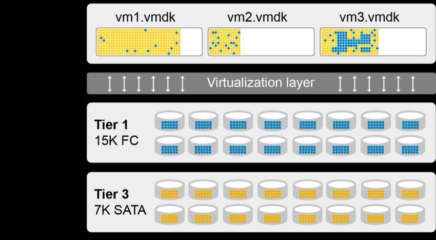
Revisions

Revisions
    Date                   Description
    July 2016              Initial release: Combined vSphere 5.x and 6.x best practice documents, added SCOS 7.1 updates
    September 2016         Minor revisions and corrections
    October 2016           Changed Disk.AutoremoveOnPDL to reflect current VMware guidance
    January 2017           Updated for vSphere 6.5 changes; added appendix D summarizing all host settings

    February 2017          Updated Linux guest disk timeout recommendations in section 4.7.2
    April 2017             Updated iSCSI login timeout recommendation
    July 2017              Updated SAS driver info in 4.2.3, Added auto UNMAP requirements in 16.3.5
    April 2018             Updated to provide vSphere 6.7 guidance
    October 2018           Minor revisions and corrections
    December 2018          Added SAS front-end lsi_msgpt3 module parameter recommendation in 4.2.3
    March 2019             Modified SATP claim rules in section 6.9.1 and appendix D
    July 2019              Minor revisions and corrections (VMFS3.EnableBlockDelete=1)
    September 2019         Claim rule syntax corrections
    April 2020             vSphere 7.0 additions
    December 2020          Minor clarifications

Acknowledgments
                 Author: Darin Schmitz

The information in this publication is provided “as is.” Dell Inc. makes no representations or warranties of any kind with respect to the information in this
publication, and specifically disclaims implied warranties of merchantability or fitness for a particular purpose.

Use, copying, and distribution of any software described in this publication requires an applicable software license.

Copyright © 2016–2020 Dell Inc. or its subsidiaries. All Rights Reserved. Dell Technologies, Dell, EMC, Dell EMC and other trademarks are trademarks
of Dell Inc. or its subsidiaries. Other trademarks may be trademarks of their respective owners. [11/24/2020] [Best Practices] [2060-M-BP-V]

2          Dell EMC SC Series: Best Practices with VMware vSphere | 2060-M-BP-V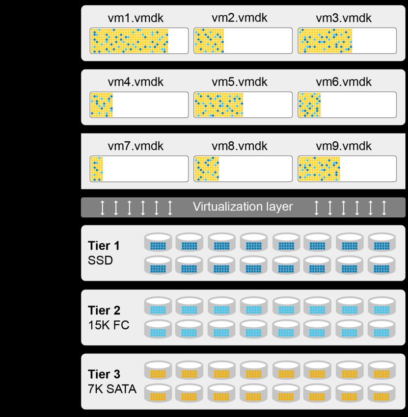
Table of contents

Table of contents
    Revisions.............................................................................................................................................................................2
    Acknowledgments ...............................................................................................................................................................2
    Table of contents ................................................................................................................................................................3
    1     Introduction ...................................................................................................................................................................6
          1.1      Audience .............................................................................................................................................................6
          1.2      Prerequisites .......................................................................................................................................................6
    2     Fibre Channel switch zoning ........................................................................................................................................7
          2.1      Single initiator multiple target zoning ..................................................................................................................7
          2.2      WWN zoning .......................................................................................................................................................7
          2.3      Port zoning..........................................................................................................................................................7
          2.4      Virtual ports.........................................................................................................................................................8
    3     Host initiator settings ....................................................................................................................................................9
    4     Modifying queue depth and timeouts .........................................................................................................................10
          4.1      Host bus adapter queue depth .........................................................................................................................10
          4.2      Storage driver queue depth and timeouts ........................................................................................................10
          4.3      Adjusting settings for permanent device loss conditions ..................................................................................13
          4.4      Modifying the VMFS queue depth for virtual machines (DSNRO) ...................................................................13
          4.5      Adaptive queue depth .......................................................................................................................................16
          4.6      Modifying the guest operating system queue depth .........................................................................................16
          4.7      Setting operating system disk timeouts ............................................................................................................17
    5     Guest virtual SCSI adapter selection .........................................................................................................................19
          5.1      BusLogic Parallel ..............................................................................................................................................19
          5.2      LSI Logic Parallel ..............................................................................................................................................19
          5.3      LSI Logic SAS...................................................................................................................................................19
          5.4      VMware Paravirtual ..........................................................................................................................................19
    6     Mapping volumes to an ESXi server ..........................................................................................................................20
          6.1      Basic volume mapping concepts ......................................................................................................................20
          6.2      Basic SC Series volume mappings ..................................................................................................................20
          6.3      Multipathed volume concepts ...........................................................................................................................21
          6.4      Multipathed SC Series volumes .......................................................................................................................22
          6.5      Configuring the VMware iSCSI software initiator for a single path ...................................................................24
          6.6      Configuring the VMware iSCSI software initiator for multipathing ....................................................................25
          6.7      iSCSI port multi-VLAN configuration recommendations...................................................................................27
          6.8      Configuring the FCoE software initiator for multipathing ..................................................................................28

3            Dell EMC SC Series: Best Practices with VMware vSphere | 2060-M-BP-V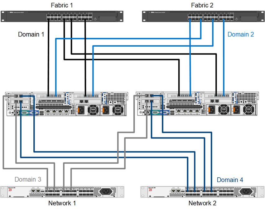
Table of contents

         6.9      VMware multipathing policies ...........................................................................................................................28
         6.10 Multipathing using a fixed path selection policy ...............................................................................................32
         6.11 Multipathing using a round robin path selection policy .....................................................................................33
         6.12 Asymmetric logical unit access (ALUA) for front-end SAS ...............................................................................33
         6.13 Unmapping volumes from an ESXi host ...........................................................................................................34
         6.14 Mapping volumes from multiple arrays .............................................................................................................35
         6.15 Multipathing resources .....................................................................................................................................35
    7    Boot from SAN............................................................................................................................................................36
         7.1      Configuring boot from SAN...............................................................................................................................36
    8    Volume creation and sizing ........................................................................................................................................38
         8.1      Volume sizing and the 64 TB limit ....................................................................................................................38
         8.2      Virtual machines per datastore .........................................................................................................................38
         8.3      VMFS partition alignment .................................................................................................................................39
         8.4      VMFS file systems and block sizes ..................................................................................................................41
    9    Volume mapping layout ..............................................................................................................................................42
         9.1      Multiple virtual machines per volume ...............................................................................................................42
         9.2      One virtual machine per volume .......................................................................................................................45
    10 Raw device mapping (RDM) ......................................................................................................................................46
    11 Data Progression and storage profile selection .........................................................................................................47
         11.1 On-Demand Data Progression .........................................................................................................................48
         11.2 Data reduction (compression and deduplication) .............................................................................................49
    12 Thin provisioning and virtual disks .............................................................................................................................51
         12.1 Virtual disk formats ...........................................................................................................................................51
         12.2 Thin provisioning relationship ...........................................................................................................................52
         12.3 SC Series thin write functionality ......................................................................................................................52
         12.4 SC Series thin provisioning or VMware thin provisioning .................................................................................52
         12.5 Windows free space recovery ..........................................................................................................................52
         12.6 Affinity Manager 2.0 ..........................................................................................................................................53
    13 Extending VMware volumes .......................................................................................................................................54
         13.1 Increasing the size of VMFS datastores ...........................................................................................................54
         13.2 Increasing the size of a virtual machine disk (VMDK) file ................................................................................55
         13.3 Increasing the size of a raw device mapping (RDM) ........................................................................................55
    14 Snapshots (replays) and virtual machine backups.....................................................................................................56
         14.1 Backing up virtual machines .............................................................................................................................56
         14.2 Recovering virtual machine data from a snapshot ...........................................................................................57
    15 Replication and remote recovery................................................................................................................................60

4           Dell EMC SC Series: Best Practices with VMware vSphere | 2060-M-BP-V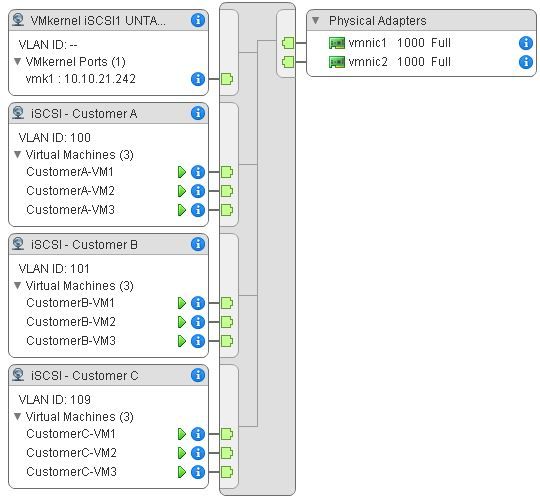
Table of contents

         15.1 Synchronous replication ...................................................................................................................................60
         15.2 Asynchronous replication .................................................................................................................................60
         15.3 Replication considerations with standard replications ......................................................................................61
         15.4 Replication considerations with Live Volumes .................................................................................................61
         15.5 Replication tips and tricks .................................................................................................................................62
         15.6 Virtual machine recovery at a DR site ..............................................................................................................63
    16 VMware storage features ...........................................................................................................................................64
         16.1 Storage I/O Controls (SIOC).............................................................................................................................64
         16.2 Storage distributed resource scheduler (SDRS) ..............................................................................................66
         16.3 vStorage APIs for array integration (VAAI) .......................................................................................................67
         16.4 vStorage APIs for Storage Awareness (VASA) ................................................................................................69
         16.5 Virtual Volumes (vVols) ....................................................................................................................................70
    A    Determining the appropriate queue depth for an ESXi host ......................................................................................71
         A.1      Fibre Channel ...................................................................................................................................................71
         A.2      iSCSI .................................................................................................................................................................72
         A.3      Using esxtop to monitor queue depth ...............................................................................................................72
    B    Deploying vSphere client plug-ins ..............................................................................................................................74
         B.1      Dell Storage vSphere Web Client plug-in .........................................................................................................74
    C    Configuring Dell Storage Manager VMware integrations ...........................................................................................75
    D    Host and cluster settings ............................................................................................................................................76
         D.1      Recommended settings ....................................................................................................................................76
         D.2      Optional settings ...............................................................................................................................................77
    E    Additional resources ...................................................................................................................................................78
         E.1      Technical support and resources .....................................................................................................................78
         E.2      VMware support................................................................................................................................................78

5           Dell EMC SC Series: Best Practices with VMware vSphere | 2060-M-BP-V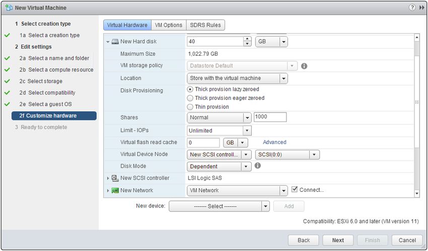
Introduction

1              Introduction
               This document provides configuration examples, tips, recommended settings, and other storage guidelines for
               integrating VMware® vSphere® hosts with the Dell EMC™ SC Series storage. It also answers many frequently
               asked questions about how VMware interacts with SC Series features like Dynamic Capacity (thin
               provisioning), Data Progression (automated tiering), and Remote Instant Replay (replication).

1.1            Audience
               This technical document is intended for storage and server administrators, and other information technology
               professionals interested in learning more about how VMware vSphere integrates with SC Series storage.

1.2            Prerequisites
               Understanding the material in this document requires formal training or advanced working knowledge of the
               following:

                   •   Installation and configuration of VMware vSphere 5.x/6.x/7.x
                   •   Configuration and operation of the SC Series
                   •   Operation of Dell EMC Storage Manager (DSM)/Enterprise Manager (EM) software
                   •   Using operating systems such as Microsoft® Windows® or Linux®

               For important information about configuring VMware ESXi® hosts to use the SAN, refer to the appropriate
               vSphere Storage Guide: VMware vSphere Documentation.

               Note: This document provides general recommendations that may not be applicable to all configurations or
               needs.

6       Dell EMC SC Series: Best Practices with VMware vSphere | 2060-M-BP-V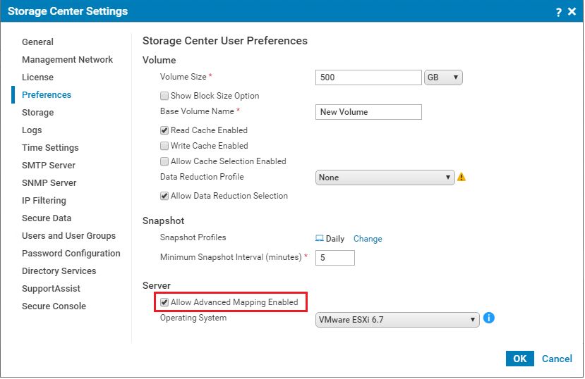
Fibre Channel switch zoning

2          Fibre Channel switch zoning
           Zoning Fibre Channel switches for an ESXi host is like zoning any other server connected to the SC Series
           array. The fundamental points are explained in this section.

2.1        Single initiator multiple target zoning
           Each Fibre Channel zone created should have a single initiator (HBA port) and multiple targets (SC Series
           front-end ports). Each HBA port requires its own Fibre Channel zone that contains itself and the SC Series
           front-end ports. Independent zones should be created for each HBA installed in the host.

2.2        WWN zoning
           When zoning by WWN, the zone only needs to contain the host HBA port and the SC Series front-end ports.
           In legacy port mode, it is not necessary to include the SC Series front-end reserve ports because they are not
           used for volume mappings. In virtual port mode, the HBA port should be zoned with the virtual port WWNs.
           For example, if the host has two HBAs connected to two disjointed fabrics, the Fibre Channel zones would
           look like the configuration shown in Table 1.

                       Example of zoning by WWN
            Name                         WWN                     Description
            ESX1-HBA1                    2100001B32017114        ESX1 HBA port 1
                                         5000D31000036001        Controller1 front-end primary plugged into fabric 1
            (zone created in fabric 1)   5000D31000036009        Controller2 front-end primary plugged into fabric 1
            ESX1-HBA2                    210000E08B930AA6        ESX1 HBA port 2
                                         5000D31000036002        Controller1 front-end primary plugged into fabric 2
                                         5000D3100003600A        Controller2 front-end primary plugged into fabric 2
            (zone created in fabric 2)

2.3        Port zoning
           Caution: Due to the supportability of port zoning, WWN zoning is preferred over port zoning.

           Port zoning is creating zones by including the physical ports instead of the WWN. Although this method has
           security advantages, it creates supportability challenges in the environment.

7      Dell EMC SC Series: Best Practices with VMware vSphere | 2060-M-BP-V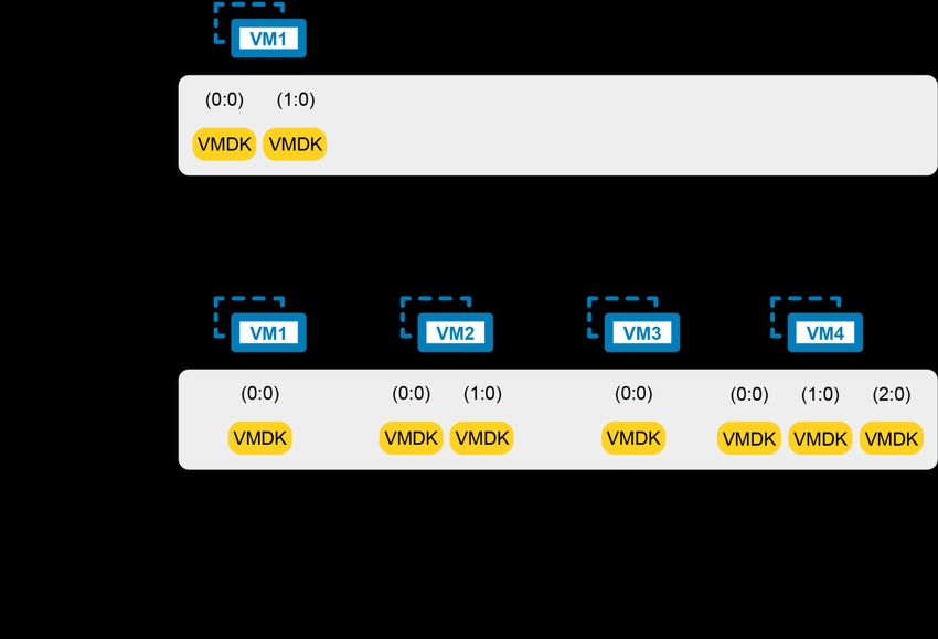
Fibre Channel switch zoning

2.4        Virtual ports
           If the SC Series array is configured to use virtual port mode, include all the front-end virtual ports within each
           fault domain in the zone with each ESXi initiator. See Figure 1.

                       Virtual port domains, Fibre Channel (FC) and iSCSI

8      Dell EMC SC Series: Best Practices with VMware vSphere | 2060-M-BP-V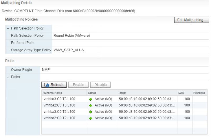
Host initiator settings

3            Host initiator settings
             Ensure the initiator settings are configured in the ESXi host according to Appendix A: Required Adapter and
             Server OS Settings in the latest Dell Storage Compatibility Matrix.

             The current recommended settings are:

                 •    QLogic® Fibre Channel card BIOS settings:

                      -   Set connection options to 1 for point to point only
                      -   Set login retry count to 60 attempts
                      -   Set port down retry to 60 attempts
                      -   Set link down timeout to 30 seconds
                      -   Set the Execution Throttle to 255 (if available). The ESXi VMkernel driver module and DSNRO
                          control the queue depth. According to the QLogic support article, HBA Execution Throttle And
                          Queue Depth In A VMware Environment, the Execution Throttle variable is not used by the
                          QLogic driver.

                 •    Emulex Fibre Channel card BIOS settings:

                      -   Set the Node Time Out field, lpfc_devloss_tmo (formerly nodev_tmo) to 60 seconds
                      -   Set topology to 2 for Auto Topology (point to point first)
                      -   Set queue depth to 255. A queue depth of 255 allows the ESXi VMkernel driver module and
                          DSNRO to more conveniently control the queue depth.

                 •    QLogic iSCSI HBAs: The ARP redirect must be enabled for controller failover to work properly with
                      iSCSI HBAs that support full hardware offload. Here is an example script for enabling ARP redirect:

                      esxcli iscsi physicalnetworkportal param set --option ArpRedirect –v=1 -A
                      vmhba4

             Note: This command will not work with dependent hardware iSCSI adapters. This command replaces the
             former esxcfg-hwiscsi command found in VMware KB Article 1010309. See the vSphere 5 Documentation
             Center article, Reference to Replacements for Service Console Commands, for an explanation of the new
             syntax.

                 •    iSCSI initiator settings for delayed ACK: During periods of high network congestion in some
                      environments, iSCSI transfer latency may exceed acceptable levels. VMware recommends disabling
                      delayed ACK using the steps described in the article, ESX/ESXi hosts might experience read or write
                      performance issues with certain storage arrays, in the VMware Knowledge Base.
                 •    SAS HBA card BIOS settings: For Dell Storage SCv2000 Series arrays configured with SAS front-end
                      ports, factory default settings within the card BIOS are recommended for SAS ESXi host HBAs.

9       Dell EMC SC Series: Best Practices with VMware vSphere | 2060-M-BP-V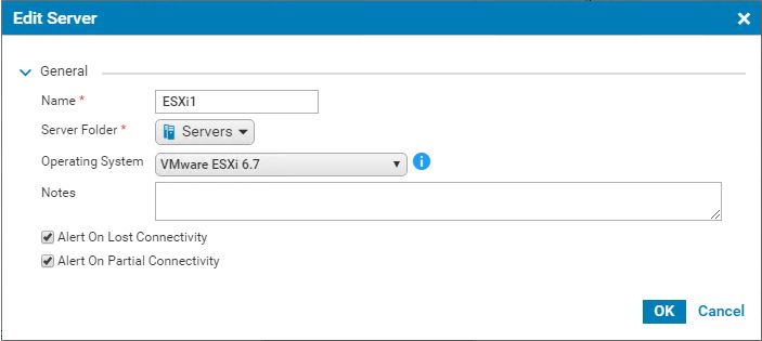
Modifying queue depth and timeouts

4          Modifying queue depth and timeouts
           Queue depth is defined as the number of disk transactions that can be in flight between an initiator and a
           target. The initiator is an ESXi host HBA port or iSCSI initiator, and the target is the SC Series front-end port.

           Since any given target can have multiple initiators sending it data, the initiator queue depth is used to throttle
           the number of transactions. Throttling transactions keeps the target from becoming flooded with I/O. When
           this flooding happens, the transactions start to pile up, causing higher latencies and degraded performance.
           While increasing the queue depth can sometimes increase performance, if it is set too high, there is an
           increased risk of overdriving the storage array.

           When data travels between the application and the storage array, there are several places where the queue
           depth can be set to throttle the number of concurrent disk transactions. The most common places where
           queue depth can be modified are listed in Table 2.

                        Areas for setting queue depth
            Area                                                  Setting
            The application itself                                Default=dependent on application
            The virtual SCSI card driver in the guest             Default=32
            The virtual machine file system (VMFS) layer          Default=32
            (DSNRO)
            The HBA VMkernel Module driver                        Default=64
            The HBA BIOS                                          Default=varies

           The remainder of this section explains how to set the queue depth in each layer.

           Caution: The appropriate queue depth for a host may vary due to several factors. As a best practice, only
           increase or decrease the queue depth if necessary. See appendix A for determining the proper queue depth.

4.1        Host bus adapter queue depth
           When configuring the host bus adapter, the Execution Throttle or queue depth should be set to 255 as to not
           gate the driver module queue depth. Depending on firmware version, the Execution Throttle variable in
           QLogic cards is unavailable because it has been deprecated in favor of the variable being set in the driver
           module. The queue depth variable within the VMkernel driver module loaded for each HBA in the system and
           DSNRO ultimately regulate the host queue depth.

4.2        Storage driver queue depth and timeouts
           The VMkernel driver module ultimately regulates the queue depth for the HBA if it needs to be changed. See
           appendix A for information about determining the appropriate queue depth.

           In addition to setting the queue depth in the driver module, the disk timeouts must also be set within the same
           command. These timeouts need to be set for the ESXi host to properly survive an SC Series controller
           failover. To configure these settings, refer to the section, Adjust Queue Depth for QLogic, Emulex, and
           Brocade HBAs, in the document, vSphere Troubleshooting in the VMware vSphere Documentation.

10     Dell EMC SC Series: Best Practices with VMware vSphere | 2060-M-BP-V
Modifying queue depth and timeouts
Caution: Before running the following commands, refer to the latest documentation from VMware for the
latest information.
4.2.1 Fibre Channel HBAs
For each of these adapters, the method to set the driver queue depth and timeouts uses the following general
steps:
1. Locate the appropriate driver name for the module that is loaded:
- For QLogic, enter:
esxcli system module list |grep ql
- For Emulex, enter:
esxcli system module list |grep lpfc
Depending on the HBA model, the output could be similar to the following:
- QLogic: qla2xxx or qlnativefc
- Emulex: lpfc820
Note: The following steps contain example module names. The actual module names should be acquired
when completing step 1.
2. Set the driver queue depth and timeouts using the esxcli command:
- For QLogic, enter:
esxcli system module parameters set -m qlnativefc -p "ql2xmaxqdepth=255
ql2xloginretrycount=60 qlport_down_retry=60"
- For Emulex, enter:
esxcli system module parameters set -m lpfc820 -p "lpfc_devloss_tmo=60
lpfc_lun_queue_depth=254"
Note: In certain multipathing configurations, the qlport_down_retry value may be set lower to decrease
failover times between paths if one of the paths fails.
3. Reboot the ESXi host for these changes to take effect.
4. To verify the settings, use the following command:
esxcli system module parameters list -m=module(i.e. -m=qla2xxx)
11 Dell EMC SC Series: Best Practices with VMware vSphere | 2060-M-BP-VModifying queue depth and timeouts
4.2.2 Software iSCSI initiator
Similarly, for the software iSCSI initiator, complete the following steps:
1. Set the queue depth to 255 (example shown):
esxcli system module parameters set -m iscsi_vmk -p iscsivmk_LunQDepth=255
2. If the login timeout is not already set to 5 seconds (the default), change it to 5 seconds (example
shown):
- Determine the iSCSI adapter name:
esxcli iscsi adapter list
- Set the login timeout parameter:
esxcli iscsi adapter param set –A=vmhba37 –k=LoginTimeout –v=5
Note: The recommended LoginTimeout value has recently changed from 60 back to the VMware default of 5.
If the ESXi host connects to both PS Series (60 recommended) and to SC Series (5 recommended), the
timeouts should be individually set at the discovery address level within the ESXi iSCSI initiator.
3. Reboot the ESXi host for the change to take effect.
4. To verify the settings, use the following commands:
esxcli system module parameters list -m iscsi_vmk
esxcli iscsi adapter param get –A=vmhba37
Note: In earlier versions of ESXi 5.x, the option to set the login timeout parameter is not available. To enable
the login timeout parameter, it may require applying the patch as described in VMware KB article 2007680.
4.2.3 SAS HBAs
For SC Series arrays that have SAS front-end ports, use the following recommendations.
For the mpt3sas, use all the default driver module settings.
For the lsi_msgpt3, change the following module parameter setting as recommended by the Dell KB article
Driver Compatibility with Front End SAS Connectivity.
esxcli system module parameters set -p issue_scsi_cmd_to_bringup_drive=0 -m
lsi_msgpt3
Caution: The driver module in use differs between ESXi versions. Review the Dell KB article Preparing
VMware ESXi Hosts to Attach to SCv20x0, SCv30x0, SC4020, SC5020 SAS Arrays for more information.
12 Dell EMC SC Series: Best Practices with VMware vSphere | 2060-M-BP-VModifying queue depth and timeouts
4.3 Adjusting settings for permanent device loss conditions
When using vSphere High Availability (HA), it is a best practice to modify the following host settings in dealing
with permanent device loss (PDL) conditions.
1. From within the host advanced system settings, apply the following modifications:
- VMkernel.Boot.terminateVMOnPDL = Yes/True (Default = No/False, Reboot required)
This setting automatically terminates a virtual machine that resides on a datastore in a PDL condition.
For example, if a storage administrator accidentally removes a path mapping to a single host causing
a PDL condition. This setting allows HA to terminate that virtual machine, and restart it on a different
host within the cluster.
- vSphere 5.5: Disk.AutoremoveOnPDL = 0 (Not the default advanced setting)
- vSphere 6.0+: Disk.AutoremoveOnPDL = 1 (default advanced setting)
This setting prevents a disk device entering a PDL state from being automatically removed from a
host, preventing an inadvertently removed device from being treated as a new device.
2. From within the HA cluster advanced options, add the following configuration parameter:
- das.maskCleanShutdownEnabled = True (Default setting = True)
This setting instructs the fault domain manager (FDM) to presume a virtual machine should be
restarted when its home datastore is not accessible.
For more information about these settings, refer to the following:
• vSphere Availability guide
• PDL Conditions and High Availability
• PDL AutoRemove feature in vSphere 5.5
4.4 Modifying the VMFS queue depth for virtual machines (DSNRO)
Disk scheduled number requests outstanding (DSNRO) is an advanced setting within each ESXi host that
controls the queue depth at the datastore level.
DSNRO is a value that can be increased or decreased depending on how many virtual machines are to be
placed on each datastore or based on the VM I/O requirements. This queue depth limit is only enforced when
more than one virtual machine per host is active on that datastore. For example, if the value is set to default,
the first virtual machine active on a datastore will have its queue depth limited only by the VMkernel driver
module. When a second, third, or fourth virtual machine is added to the datastore, during contention the limit
will be enforced to the maximum queue depth of 32 (or as modified).
Note: Previous to ESXi 5.5, DSNRO was a global setting named Disk.SchedNumReqOutstanding that
applied to all datastores. Modifying DSNRO for an individual datastore was not possible.
13 Dell EMC SC Series: Best Practices with VMware vSphere | 2060-M-BP-VModifying queue depth and timeouts
Example queue utilization with the DSNRO set to 32.
Note: The DSNRO limit does not apply to volumes mapped as raw device mappings (RDMs). Each RDM will
have its own queue.
The DSNRO setting can be modified on a per-datastore basis using the command line:
esxcli storage core device set -d -O
Note: This setting allows fine-tuning of DSNRO on a per-volume basis, however it must be set on each
datastore (and each host) if the queue depth is greater than 32.
To globally set the DSNRO, the easiest method is to use a scripting tool such as the VMware PowerCLI utility.
The following example script demonstrates setting the DSNRO to 64 globally across all datastores, on each
host. Remember that any volume added after this script is ran would need to be changed manually or by
rerunning the script.
14 Dell EMC SC Series: Best Practices with VMware vSphere | 2060-M-BP-VModifying queue depth and timeouts
Example PowerCLI Script (dsnro.ps1):
#Connect to vCenter. Change server, user, and password credentials below
Connect-VIServer -Server ‘vCenter_Server_IP_or_FQDN’ -User
‘administrator@vsphere.local’ -Password ‘thepassword’
#Change this variable to the desired dsnro (Default=32 Max=64)
$dsnro = 64
#Retrieve a list of ALL ESXi hosts from the vCenter server
$esxhosts = get-vmhost
#Cycle through each host retrieving all storage devices associated with that
host
foreach ($hostname in $esxhosts)
{
$esxcli = Get-EsxCli -VMHost $hostname
$devices = $esxcli.storage.core.device.list()
foreach ($device in $devices)
{
if ($device.Vendor -like "COMPELNT")
{
$esxcli.storage.core.device.set($false, $null, $device.Device, $null,
$null, $null, $null, $null, $null, $null, $null, $dsnro,$null,$null)
$esxcli.storage.core.device.list()
}
}
}
As a best practice for modifying any host settings, run tests to determine the impact of changing this variable
beforehand. Once successful tests have been completed, as a precautionary measure, it is recommended
only to run this script during a maintenance window. Since DSNRO helps to ensure fairness across the virtual
machines residing on a datastore, modifying this value could lead to individual virtual machines monopolizing
disk resources.
More information about the DSNRO can be found in the following documentation:
• “Change Maximum Outstanding Disk Requests in the vSphere Web Client” in the appropriate
vSphere Troubleshooting guide: VMware vSphere documentation
• Setting the Maximum Outstanding Disk Requests for virtual machines (1268) in the VMware
Knowledge Base
15 Dell EMC SC Series: Best Practices with VMware vSphere | 2060-M-BP-VModifying queue depth and timeouts
4.5 Adaptive queue depth
At times of high congestion, VMware has an adaptive queue depth algorithm that can be enabled with the
QFullSampleSize and QFullThreshold variables. These variables aid in relieving the congestion by
dynamically reducing and increasing the logical unit number (LUN) queue depth. Due to the architecture of
SC Series storage, enabling these settings is not recommended unless under the guidance of Dell Support.
For more information, see Controlling LUN queue depth throttling in VMware ESX/ESXi in the VMware
Knowledge Base.
4.6 Modifying the guest operating system queue depth
The queue depth can also be set within the guest operating system if needed. Windows operating systems
have a default queue depth of 32 set for each vSCSI controller, but can be increased up to 128 if necessary.
The method to adjust the queue depth varies between operating systems. Examples are shown in section
4.6.1. Extra vSCSI adapters can be added to a virtual machine to increase the total queue depth available to
the virtual machine.
4.6.1 Windows Server
To adjust the queue depth for the LSI® Logic drivers, add or modify the following registry keys:
1. Before beginning, back up the registry.
2. Use regedit to add the following keys:
a. For LSI Logic Parallel (LSI_SCSI):
Windows Registry Editor Version 5.00
[HKLM\SYSTEM\CurrentControlSet\Services\LSI_SCSI\Parameters\Device]
"DriverParameter"="MaximumTargetQueueDepth=128;"
; The semicolon is required at the end of the queue depth value
"MaximumTargetQueueDepth"=dword:00000080
; 80 hex is equal to 128 in decimal
Registry settings for the LSI Logic Parallel vSCSI adapter
16 Dell EMC SC Series: Best Practices with VMware vSphere | 2060-M-BP-VModifying queue depth and timeouts
b. For LSI Logic SAS (LSI_SAS):
Windows Registry Editor Version 5.00
[HKLM\SYSTEM\CurrentControlSet\Services\LSI_SAS\Parameters\Device]
"DriverParameter"="MaximumTargetQueueDepth=128;"
; The semicolon is required at the end of the queue depth value
"MaximumTargetQueueDepth"=dword:00000080
; 80 hex is equal to 128 in decimal
Registry setting for the LSI Logic SAS vSCSI Adapter
c. For VMware Paravirtual SCSI (PVSCSI), the Paravirtual adapter is different from the LSI vSCSI
adapters in that its queue depth can be adjusted higher: Up to 256 for devices and 1024 for the
adapter.
For more information, see the VMware KB article, Large-scale workloads with intensive I/O
patterns might require queue depths significantly greater than Paravirtual SCSI default values.
3. Reboot the virtual machine.
Note: See the VMware Knowledge Base for the most current information about setting the queue depth with
different vSCSI controllers or operating systems.
4.7 Setting operating system disk timeouts
For each operating system, if VMware tools are not installed, the disk timeouts must be set to 60 seconds for
the operating system to handle storage controller failovers properly.
Examples of setting the operating-system timeouts can be found in the section, “Set Timeout on Windows
Guest OS” in the vSphere Storage Guide at VMware vSphere documentation.
The general steps to set the disk timeout within Windows and Linux are listed in the following sections.
17 Dell EMC SC Series: Best Practices with VMware vSphere | 2060-M-BP-VModifying queue depth and timeouts
4.7.1 Windows
1. Back up the registry.
2. Using the Registry Editor, modify the following key.
Windows Registry Editor Version 5.00
[HKLM\SYSTEM\CurrentControlSet\Services\Disk]
"TimeOutValue"=dword:0000003c
; 3c in hex is equal to 60 seconds in decimal
Registry key to set the Windows disk timeout
3. Reboot the virtual machine.
Note: This registry value is automatically set when installing VMware Tools. For more information, see
Inconsistent Windows virtual machine performance when disks are located on SAN datastores in the VMware
Knowledge Base.
4.7.2 Linux
For more information about setting disk timeouts in Linux, refer to the VMware Knowledge Base article,
Increasing the disk timeout values for a Linux 2.6 virtual machine.
Caution: For Red Hat Enterprise Linux 7.x virtual machines, verify the disk timeouts are correctly set to 60
seconds. For more information, see the Red Hat knowledge base (login required), article 1578643: The udev
rules for SCSI timeout are missing in open-vm-tools package in Red Hat Enterprise Linux 7.
18 Dell EMC SC Series: Best Practices with VMware vSphere | 2060-M-BP-VGuest virtual SCSI adapter selection
5 Guest virtual SCSI adapter selection
When creating a new virtual machine, there are four types of virtual SCSI (vSCSI) controllers to choose from.
Based on the operating system selected, vSphere will automatically recommend and select a SCSI controller
that is best suited for that particular operating system. The best practice is to follow the client
recommendation. The nuances of each adapter are described in the following subsections.
vSCSI adapter selection
5.1 BusLogic Parallel
This vSCSI controller is used for older operating systems. Due to the queue depth limitations of this controller,
it is not recommended unless it is the only option available for that particular operating system. Certain
versions of Windows issue only enough I/O to fill a queue depth of one.
5.2 LSI Logic Parallel
Because many operating systems support this vSCSI adapter, it is recommended for virtual machines that do
not support the LSI Logic SAS adapter.
5.3 LSI Logic SAS
This vSCSI controller is available for virtual machines with hardware versions 7 and later. It also has similar
performance characteristics of the LSI Logic Parallel. This adapter adds support for SCSI-3 reservations,
which are required for Microsoft Cluster Services (MSCS). Some operating system vendors are gradually
withdrawing support for SCSI in favor of SAS, making the LSI Logic SAS controller a good choice for future
compatibility.
5.4 VMware Paravirtual
This vSCSI controller is a high-performance adapter that can result in greater throughput and lower CPU
utilization. More information about the usage and limitations of this adapter can be found in the section, About
VMware Paravirtual SCSI Controllers, in the vSphere Virtual Machine Administration Guide in the VMware
vSphere documentation.
19 Dell EMC SC Series: Best Practices with VMware vSphere | 2060-M-BP-VMapping volumes to an ESXi server
6 Mapping volumes to an ESXi server
Within the SC Series, mapping is the process of presenting a volume to a host. The following subsections
describe basic concepts on how vSphere treats different scenarios.
6.1 Basic volume mapping concepts
When sharing volumes between ESXi hosts for vMotion, HA, and DRS, for consistency it is recommended
that each volume is mapped to clustered ESXi hosts using the same LUN.
For example:
• There are three ESXi hosts named ESXi1, ESXi2, and ESXi3
• A new volume is created named "LUN10-vm-storage"
• This volume must be mapped to each of the ESXi hosts as the same LUN:
Volume: "LUN10-vm-storage" → Mapped to ESXi1 -as- LUN 10
Volume: "LUN10-vm-storage" → Mapped to ESXi2 -as- LUN 10
Volume: "LUN10-vm-storage" → Mapped to ESXi3 -as- LUN 10
6.2 Basic SC Series volume mappings
In SCOS versions 5.x and later, the mapping process is automated by creating a server cluster object. This
feature allows the volume to be mapped to multiple ESXi hosts simultaneously, automatically keeping the
LUN numbering consistent for all the paths.
Example of a server cluster object
As an added benefit, when a new ESXi host is placed into the server cluster, all the existing volume mappings
assigned to the cluster object are applied. Meaning that if the cluster has 100 volumes mapped to it,
presenting them to a new ESXi host is as simple as adding it to the cluster object.
Similarly, if the host is removed from the server cluster, the cluster mappings are removed. All I/O must be
stopped from the host before volumes are removed. Only volumes that are mapped to an individual host,
such as the boot volume, will remain once a host is removed from the server cluster.
20 Dell EMC SC Series: Best Practices with VMware vSphere | 2060-M-BP-VMapping volumes to an ESXi server
In the mapping wizard, the system can auto select the LUN number, or a preferred LUN number can be
manually specified from the advanced settings screen shown in Figure 8.
Manually specifying a LUN in the advanced settings screen
This advanced option allows administrators who already have a LUN numbering scheme to continue using it.
However, if a LUN is not manually specified, the system automatically selects a LUN for each volume
incrementally starting at LUN 1.
Timesaver: When naming volumes from within the SC Series user interface, it may be helpful to specify the
LUN number as part of the volume name. This naming helps to quickly identify which volumes are mapped
using each LUN.
6.3 Multipathed volume concepts
If there are ESXi hosts that have multiple initiator ports, ESXi has integrated functionality to provide native
multipathing of volumes over multiple supported protocols.
Building on the previous example, here is an example of multipathing mappings:
Volume: "LUN10-vm-storage" → Mapped to ESXi1/HBA1 -as- LUN 10
Volume: "LUN10-vm-storage" → Mapped to ESXi1/HBA2 -as- LUN 10
Volume: "LUN10-vm-storage" → Mapped to ESXi2/HBA1 -as- LUN 10
Volume: "LUN10-vm-storage" → Mapped to ESXi2/HBA2 -as- LUN 10
Volume: "LUN10-vm-storage" → Mapped to ESXi3/HBA1 -as- LUN 10
Volume: "LUN10-vm-storage" → Mapped to ESXi3/HBA2 -as- LUN 10
Note: With older versions of ESXi, if the LUN number is not consistent between multiple hosts or multiple
HBAs, VMFS datastores may not be visible to all nodes.
21 Dell EMC SC Series: Best Practices with VMware vSphere | 2060-M-BP-VMapping volumes to an ESXi server
Keep in mind that when a volume uses multiple paths, both the ESXi initiators are mapped from the same
controller, through different front-end ports. For example:
"LUN10-vm-storage" → Controller1/Port1 → FC-Switch-1 → Mapped to ESXi1/HBA1 as LUN 10
"LUN10-vm-storage" → Controller1/Port2 → FC-Switch-2 → Mapped to ESXi1/HBA2 as LUN 10
If a different volume is active on the second controller, it may be mapped such as:
"LUN20-vm-storage" → Controller2/Port1 → FC-Switch-1 → Mapped to ESXi1/HBA1 as LUN 20
"LUN20-vm-storage" → Controller2/Port2 → FC-Switch-2 → Mapped to ESXi1/HBA2 as LUN 20
When configuring multipathing, remember that a volume cannot be mapped to both controllers
simultaneously, because a volume can only be active on one controller at a time.
6.4 Multipathed SC Series volumes
When multipathing SC Series volumes, the process is automated. Selecting the correct operating system in
the server properties screen can prevent many of the common mapping errors. Based on the operating
system selected, SC Series correctly maps volumes by applying a set of rules to the server that are unique to
each operating system.
Server operating system selection
22 Dell EMC SC Series: Best Practices with VMware vSphere | 2060-M-BP-VMapping volumes to an ESXi server
Multipathing to an ESXi host is automatic when the server object has more than one HBA or iSCSI initiator
ports assigned to it. In other words, the advanced options must be used if the server does not need a volume
multipathed.
Advanced server mapping options
Advanced mapping options for an ESXi host
Function Description
Select LUN Clear the Use next available LUN option to manually specify the LUN. If
this box is not checked, the system automatically assigns the next
available LUN.
Restrict Mapping Paths Use this option when a volume only needs to be mapped to a specific
HBA in the ESXi host.
Configure Multipathing This option designates how many of the SC Series front-end ports
allowed for the volume to be mapped through. For example, if each
controller has four front-end ports, selecting unlimited maps the volume
through all four. Selecting two only uses two of the four front-end ports.
The system automatically selects the two front-end ports with the fewest
mappings.
Configure Volume Use VMFS does not recognize read-only mappings, so this option should not
be used.
23 Dell EMC SC Series: Best Practices with VMware vSphere | 2060-M-BP-VMapping volumes to an ESXi server
6.5 Configuring the VMware iSCSI software initiator for a single path
Although it is not recommended, for instances where iSCSI multipathing cannot be configured, the steps
required for a single-path iSCSI configuration are as follows.
From within the VMware vSphere Client:
1. In the ESXi host Security Profile > ESXi firewall, enable the Software iSCSI Client.
2. Add a VMkernel port to a virtual switch assigned to the physical NIC for iSCSI (see Figure 11).
Configuring the VMkernel port
3. From the Storage Adapters configuration screen, click the plus sign to add an adapter, select
Software iSCSI Adapter, and click OK.
4. Within the Storage Adapters area, highlight the iSCSI software adapter (such as vmhba38).
5. To add the SC Series front-end ports, select Targets, then select the Dynamic Discovery tab. Click
Add and enter the iSCSI control port IP address, labeled as the well-known IP address for the fault
domain. If virtual ports are not enabled for iSCSI front-end ports, each of the iSCSI adapter IP
addresses for the system must be added manually.
6. Rescan the iSCSI initiator.
7. From DSM:
a. Create a server object for the ESXi host.
b. Map a volume to the ESXi host.
8. From within the VMware vSphere client, browse the Storage Adapters section and rescan the iSCSI
HBA for new volumes.
24 Dell EMC SC Series: Best Practices with VMware vSphere | 2060-M-BP-VMapping volumes to an ESXi server
6.6 Configuring the VMware iSCSI software initiator for multipathing
To configure the VMware iSCSI software initiator for multipathing, see sections “Configuring Software iSCSI
Adapter” and “Multiple Network Adapters in iSCSI Configuration” in the vSphere Storage Guide at VMware
vSphere documentation.
For users with previous experience configuring iSCSI for multipathing, here are a few key points for a
successful configuration:
• Verify that there is one VMkernel interface for each physical NIC to be used for storage traffic,
following the virtual switch port binding recommendations in section 6.6.1.
• Adjust the failover order on each VMkernel interface for a 1:1 VMkernel to physical NIC ratio.
• Add both VMkernel interfaces to the iSCSI software adapter network port binding (see Figure 12). If
the prerequisite failover orders have not been set, the vSphere client will not allow the operation.
• Rescan the iSCSI software adapter for new volumes.
• From within the Dell Storage Manager Client, create the server object for the host.
Binding multiple VMkernel ports to the software iSCSI initiator
6.6.1 VMkernel port binding considerations with software iSCSI
When using the software iSCSI initiator provided within an ESXi host, careful consideration needs to be given
to the appropriate virtual switch configurations adhering to VMware iSCSI port-binding requirements. The
number of fault domains, subnets, and IP configuration need to be carefully examined to avoid configuration
errors. If iSCSI front-end ports are configured in a single subnet and single fault domain, the vmnics must
reside within a single vSwitch to use VMkernel port binding.
Note: The most common environment in which a single fault domain is used for the iSCSI network is a
redundant configuration with a single VLAN.
25 Dell EMC SC Series: Best Practices with VMware vSphere | 2060-M-BP-VMapping volumes to an ESXi server
For example, with subnet 192.168.0.x and subnet mask 255.255.255.0, the vSwitch would look like Figure 13.
iSCSI ports and NICs on a single vSwitch/single subnet (VMkernel port binding allowed)
Note: Using port binding is not recommended when the VMkernel ports are on different networks as shown in
Figure 14, because it may cause long rescan times and other problems. See Considerations for using
software iSCSI port binding in ESX/ESXi in the VMware Knowledge Base.
In configurations using multiple fault domains, with the iSCSI front-end ports configured in a multiple subnet
and multiple fault domain configurations, ensure either:
• VMkernel ports and vmnics reside in separate vSwitches (see Figure 14)
OR
• Failover order ensures one VMkernel per physical NIC in a single vSwitch
Due to the network separation, VMkernel port binding must not be used.
iSCSI VMkernel ports and NICs on multiple vSwitches/multiple subnets (port binding must not
be used).
26 Dell EMC SC Series: Best Practices with VMware vSphere | 2060-M-BP-VMapping volumes to an ESXi server
6.7 iSCSI port multi-VLAN configuration recommendations
For SC Series systems with iSCSI capabilities, SCOS 6.5 and later has multiple-VLAN support for diverse
network configurations and multitenant environments. This multi-VLAN support allows iSCSI storage I/O to be
separated between vSwitches for customers using software iSCSI initiators within the guest. It also allows
admins to isolate specific ESXi host-cluster VMkernel ports to their own dedicated iSCSI storage VLAN.
VLANs assigned to vSwitches isolating in-guest iSCSI initiator traffic for customers
Since iSCSI traffic is not encrypted in its plain form, it is a best practice to isolate that traffic for security
purposes. A common misconception is that CHAP encrypts iSCSI traffic, but it only provides authentication for
the connection to prevent unauthorized access.
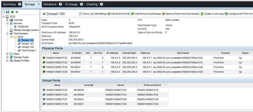
Note: In older versions of DSM, the configuration of iSCSI VLANs is functionality that can only be configured
through the traditional Dell Storage Manager Client.
27 Dell EMC SC Series: Best Practices with VMware vSphere | 2060-M-BP-VMapping volumes to an ESXi server
Configuration of VLANs within the Dell Storage Manager (Enterprise Manager) client
Note: For added flexibility, Jumbo frames can be enabled on a per-fault-domain basis.
6.8 Configuring the FCoE software initiator for multipathing
When using the ESXi software FCoE, volumes are assigned to the VMW_SATP_LOCAL by default. In some
instances, this default policy will cause paths to go unclaimed. To remedy this situation, it may be necessary
to adjust the claim rules on each ESXi host so that FCoE volumes are correctly assigned to the
VMW_SATP_ALUA.
esxcli storage nmp satp rule add -R fcoe -s VMW_SATP_ALUA
6.9 VMware multipathing policies
When configuring the path-selection policy of each datastore or volume, administrators have the choice of
round robin, fixed, or most recently used. The default path selection policy for the SC Series system depends
on the SCOS version and the associated SATP module detected. Round robin is highly recommended for
ease of management if there are no technical reasons against using it (such as with Microsoft failover
clusters).
28 Dell EMC SC Series: Best Practices with VMware vSphere | 2060-M-BP-VMapping volumes to an ESXi server
6.9.1 Round robin policy for standard volumes
The round robin path selection policy uses automatic path selection and load balancing to rotate I/O through
all paths. Round robin load balancing does not aggregate the storage link bandwidth. It merely distributes the
load for the datastore volume in bursts evenly and sequentially across paths in an alternating fashion.
Using round robin reduces the management headaches of manually balancing the storage load across all
storage paths as with a fixed policy. However, there are certain situations where using round robin does not
make sense. For instance, it is not considered a best practice to enable round robin between an iSCSI path
and Fibre Channel path. It is also not best practice to balance the load between an 8 Gb FC and a 16 Gb FC
path. With round robin, care must be taken to ensure all the paths included are identical in type, speed, and
have the same queue depth settings.
Here is an example of what happens during a path failure when using round robin:
1. Load is distributed evenly between HBA1 and HBA2
2. HBA1 loses connectivity; HBA2 will assume all I/O load
3. HBA1 resumes connectivity; load is distributed evenly again between both
Example of a datastore path selection policy set to round robin
29 Dell EMC SC Series: Best Practices with VMware vSphere | 2060-M-BP-VYou can also read