Agisoft Metashape User Manual - Standard Edition, Version 1.7
←
→
Page content transcription
If your browser does not render page correctly, please read the page content below
Agisoft Metashape User Manual
   Standard Edition, Version 1.7
Agisoft Metashape User Manual: Standard Edition, Version 1.7
Publication date 2021
Copyright © 2021 Agisoft LLC
Table of Contents
Overview .......................................................................................................................... v
How it works ............................................................................................................. v
About the manual ....................................................................................................... v
1. Installation and Activation ................................................................................................ 1
System requirements ................................................................................................... 1
GPU recommendations ................................................................................................ 1
Installation procedure .................................................................................................. 2
30-day trial and demo mode ......................................................................................... 3
Activation procedure ................................................................................................... 3
2. Capturing scenarios ......................................................................................................... 5
Equipment ................................................................................................................. 5
Camera settings .......................................................................................................... 5
Object/scene requirements ............................................................................................ 5
Image preprocessing ................................................................................................... 5
Capturing scenarios ..................................................................................................... 6
Restrictions ............................................................................................................... 7
Lens calibration .......................................................................................................... 7
Excessive image elimination ....................................................................................... 10
3. General workflow ......................................................................................................... 11
Preferences settings ................................................................................................... 11
Loading images ........................................................................................................ 12
Aligning photos ........................................................................................................ 14
Building dense point cloud ......................................................................................... 19
Building mesh .......................................................................................................... 21
Building model texture .............................................................................................. 24
Saving intermediate results ......................................................................................... 29
Exporting results ....................................................................................................... 30
Camera track creation and fly through video rendering .................................................... 37
4. Improving camera alignment results ................................................................................. 39
Camera calibration .................................................................................................... 39
Optimization ............................................................................................................ 41
5. Editing ........................................................................................................................ 43
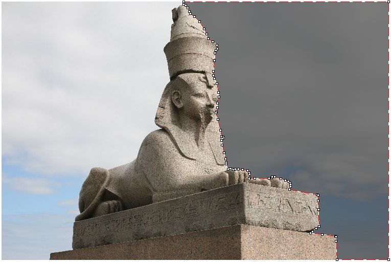
Using masks ............................................................................................................ 43
Editing point cloud ................................................................................................... 48
Editing model geometry ............................................................................................. 53
6. Automation .................................................................................................................. 59
Using chunks ........................................................................................................... 59
A. Graphical user interface ................................................................................................. 65
Application window .................................................................................................. 65
Menu commands ...................................................................................................... 69
Toolbar buttons ........................................................................................................ 75
Hot keys ................................................................................................................. 77
B. Supported formats ......................................................................................................... 79
Images .................................................................................................................... 79
Camera calibration .................................................................................................... 79
Interior and exterior camera orientation parameters ......................................................... 79
Tie points ................................................................................................................ 80
Sparse/dense point cloud ............................................................................................ 80
Mesh model ............................................................................................................. 81
Texture maps ........................................................................................................... 81
C. Camera models ............................................................................................................ 82
iiiAgisoft Metashape User Manual
Frame cameras ......................................................................................................... 83
Fisheye cameras ....................................................................................................... 83
ivOverview
Agisoft Metashape is a stand-alone software product that performs photogrammetric processing of digital
images (aerial and close-range photography) and generates 3D spatial data to be used in GIS applications,
cultural heritage documentation, and visual effects production as well as for indirect measurements of
objects of various scales.
The software allows to process images from RGB, thermal into the spatial information in the form of dense
point clouds, textured polygonal models. Wisely implemented digital photogrammetry technique enforced
with computer vision methods results in smart automated processing system that, on the one hand, can be
managed by a new-comer in the field of photogrammetry, yet, on the other hand, has a lot to offer to a
specialist who can benefit from advanced features like stereoscopic mode and have complete control over
the results accuracy, with detailed report being generated at the end of processing.
How it works
Typical tasks for a photogrammetry processing project in Metashape is to build a textured 3D model.
Imagery data processing procedure with Agisoft Metashape consists of two main steps.
1. The first step is called alignment. It includes aerial triangulation (AT) and bundle block adjustment
(BBA). At this stage Metashape searches for feature points on the images and matches them across
images into tie points. The program also finds the position of the camera for each image and
refines camera calibration parameters (estimates internal (IO) and external (EO) camera orientation
parameters).
The results of these procedures are visualized in the form of a sparse point cloud and a set of camera
positions. The sparse point cloud represents the results of image alignment and will not be directly used
in further processing (except for the sparse point cloud based surface reconstruction method, which
is suitable only for quick estimates, e.g., of completeness of a data set). But the sparse point cloud
is necessary for the determination of depth maps (based on the sparse cloud selected stereo pairs).
However it can be exported for further usage in external programs. For instance, a sparse point cloud
model can be used in a 3D editor as a reference. On the contrary, the set of camera positions is required
for further 3D surface reconstruction by Metashape.
2. The second step is generation of a surface in 3D (mesh) . Polygonal model (mesh) can be textured for
photorealistic digital representation of the object/scene and exported in numerous formats compatible
with post-processing software, both for CAD and 3D-modeling workflows.
Dense point cloud can be built by Metashape based on the estimated camera positions and images
themselves (dense stereo matching). Generated photogrammetric point cloud can be merged with
LIDAR data.
About the manual
Basically, the sequence of actions described above covers most of the data processing needs. All these
operations are carried out automatically according to the parameters set by user. Instructions on how to
get through these operations and descriptions of the parameters controlling each step are given in the
corresponding sections of the Chapter 3, General workflow chapter of the manual.
In some cases, however, additional actions may be required to get the desired results. Pictures taken using
uncommon lenses such as fisheye one may require preliminary calibration of optical system parameters
or usage of different calibration model specially implemented for ultra-wide angle lens. Metashape
vOverview
enables to reestimate extrinsic and intrinsic camera parameters, optimizing them for a tie point pool
preliminary filtered by user. Chapter 4, Improving camera alignment results covers that part of the
software functionality. In some capturing scenarios masking of certain regions of the photos may be
required to exclude them from the calculations. Application of masks in Metashape processing workflow
as well as editing options available are described in Chapter 5, Editing. Chapter 6, Automation describes
opportunities to save up on manual intervention to the processing workflow.
It can take up quite a long time to reconstruct a 3D model. Metashape allows to export obtained results
and save intermediate data in a form of project files at any stage of the process. If you are not familiar with
the concept of projects, its brief description is given at the end of the Chapter 3, General workflow.
In the manual you can also find instructions on the Metashape installation and activation procedures and
basic rules for taking "good" photographs, i.e. pictures that provide most necessary information for 3D
reconstruction. For the information refer to Chapter 1, Installation and Activation and Chapter 2, Capturing
scenarios.
viChapter 1. Installation and Activation
System requirements
Minimal configuration
• Windows 7 SP 1 or later (64 bit), Windows Server 2008 R2 or later (64 bit), macOS High Sierra or
later, Debian/Ubuntu with GLIBC 2.19+ (64 bit)
• Intel Core 2 Duo processor or equivalent
• 4 GB of RAM
Recommended configuration
• Windows 7 SP 1 or later (64 bit), Windows Server 2008 R2 or later (64 bit), macOS Mojave or later,
Debian/Ubuntu with GLIBC 2.19+ (64 bit)
• Intel Core i7 or AMD Ryzen 7 processor
• Discrete NVIDIA or AMD GPU (4+ GB VRAM)
• 32 GB of RAM
The number of photos that can be processed by Metashape depends on the available RAM and
reconstruction parameters used. Assuming that a single photo resolution is of the order of 10 MPix, 4 GB
RAM is sufficient to make a model based on 30 to 50 photos. 16 GB RAM will allow to process up to
300-400 photographs.
GPU recommendations
Metashape supports accelerated image matching; depth maps reconstruction; depth maps based mesh
model generation; texture blending; photoconsistent mesh refinement operation due to the graphics
hardware (GPU) exploiting.
NVIDIA
GeForce GTX 7xx series and later with CUDA support.
AMD
Radeon R9 series and later with OpenCL 1.2 support.
Metashape is likely to be able to utilize processing power of any CUDA enabled device with compute
capability 3.0 and higher or OpenCL 1.2 and higher enabled device with SPIR support for stages specified
above, provided that CUDA/OpenCL drivers for the device are properly installed. However, because of
the large number of various combinations of video chips, driver versions and operating systems, Agisoft
is unable to test and guarantee Metashape's compatibility with every device and on every platform.
The processing performance of the GPU device is mainly related to the number of CUDA cores for
NVIDIA video chips and the number of shader processor units for AMD and Intel video chips. Additionally
depth maps based mesh model reconstruction as well as photoconsistent mesh refinement operations and
texture blending would benefit from larger amount of VRAM available.
1Installation and Activation
The table below lists currently supported devices (on Windows platform only). Agisoft will pay particular
attention to possible problems with Metashape running on these devices.
Table 1.1. Supported Desktop GPUs on Windows platform
NVIDIA AMD
GeForce RTX 3080 Radeon RX 6800
GeForce RTX 2080 Ti Radeon VII
Tesla V100 Radeon RX 5700 XT
Tesla M60 Radeon RX Vega 64
Quadro P6000 Radeon RX Vega 56
Quadro M6000 Radeon Pro WX 7100
GeForce TITAN X Radeon RX 580
GeForce GTX 1080 Ti FirePro W9100
GeForce GTX TITAN X Radeon R9 390x
GeForce GTX 980 Ti Radeon R9 290x
GeForce GTX TITAN
GeForce GTX 780 Ti
Metashape supports texture blending on GPU using Vulkan technology on Linux and Windows OS. GPU
accelerated texture blending is currently supported for frame and fisheye type cameras on NVIDIA cards
since GeForce GTX 8XX / Quadro M4000 and driver versions from 435.xx and on AMD cards since
Radeon R9 29x series / FirePro W9100 and 17.1.x drivers. Some older GPUs and older driver versions
could also support texture blending using Vulkan, however, it is not guaranteed.
Although Metashape is supposed to be able to utilize other compatible GPU models and being run under
a different operating system, Agisoft does not guarantee that it will work correctly. However, all GPU-
based processing issues should be reported to Agisoft support team for more detailed investigation.
Note
• Use CPU enable flag to allow calculations both on CPU and GPU for GPU-supported tasks.
However if at least one powerful discrete GPU is used it is recommended to disable CPU flag
for stable and rapid processing.
• Using GPU acceleration with mobile or integrated graphics video chips is not recommended
because of the low performance of such GPUs.
• CUDA supported devices for some older macOS versions may require to install CUDA drivers
from official web-site first: http://www.nvidia.com/object/mac-driver-archive.html.
Due to lack of CUDA support on certain macOS versions Metashape will automatically switch
to OpenCL implementation for GPU-based processing on NVIDIA graphic devices.
Installation procedure
Installing Metashape on Microsoft Windows
To install Metashape on Microsoft Windows simply run the downloaded msi file and follow the
instructions.
2Installation and Activation
Installing Metashape on macOS
Open the downloaded dmg image and drag Metashape application bundle to the desired location on your
hard drive (for example, to Applications folder. Do not run Metashape directly from the dmg image to
avoid issues on license activation step.
Installing Metashape on Debian/Ubuntu
Unpack the downloaded archive with a program distribution kit to the desired location on your hard drive.
Also, install the package: sudo apt install libxcb-xinerama0. Start Metashape by running metashape.sh
script from the program folder.
30-day trial and demo mode
Once Metashape is downloaded and installed on your computer you can run it either in the Demo mode or
in the full function mode. On every start until a license key sequence is entered it will show on activation
dialog offering three options: (1) activate Metashape using a valid license code, (2) start a free 30-day
trial, (3) continue using Metashape in Demo mode. Starting a 30-day trial period allows to evaluate the
functionality of the program and explore the software in full-function mode, including save and export
features. Trial license is intended to be used for evaluation purposes only and any commercial use of a
trial license is prohibited.
If you are not ready yet to start the trial period, you can opt for the Demo mode. The employment of
Metashape in the Demo mode is not time limited. Several functions, however, are not available in the
Demo mode. These functions are the following:
• save the project;
• all export features, including exporting reconstruction results (you can only view a 3D model on the
screen);
To use Metashape in the full function mode for various projects you have to purchase a license. On
purchasing you will get a license code to be entered into the activation dialog of Metashape. Once the
license code is entered you will get full access to all functions of the program and the activation dialog
will no longer appear upon program start, unless the license is deactivated.
Activation procedure
Metashape license activation
Metashape software requires license key (a digital code) to be activated. First of all, make sure that you
have a valid license key or a trial code at hand.
To activate Metashape
1. Launch Metashape software, previously installed on your machine, and go to Help menu for Activate
product... command.
2. In Activation dialog insert license key according to the suggested 5 digit blocks structure. Please note
that license codes does never include zero digit - only letter "O".
3. If the license code has been input correctly, then the OK button will become active. Click on it to
complete the activation procedure. If the button is still grayed out, please make sure that the key you
3Installation and Activation
are using is meant for the product you are trying to activate: a license key for the Professional Edition,
for example, will not activate the Standard version of the software.
Note
• The node-locked license activation on Windows OS and macOS may require administrator
privileges. During the activation process additional confirmation dialog will appear to apply the
elevated privileges.
4Chapter 2. Capturing scenarios
Photographs suitable for 3D model reconstruction in Metashape can be taken by any digital camera (both
metric and non-metric), as long as you follow some specific capturing guidelines. This section explains
general principles of taking and selecting pictures that provide the most appropriate data for 3D model
generation.
IMPORTANT! Make sure you have studied the following rules and read the list of restrictions before you
get out for shooting photographs.
Equipment
• Use a digital camera with reasonably high resolution (5 MPix or more).
• Avoid ultra-wide angle and fisheye lenses. The best choice is 50 mm focal length (35 mm film
equivalent) lenses. It is recommended to use focal length from 20 to 80 mm interval in 35mm equivalent.
If a data set was captured with fisheye lens, appropriate camera sensor type should be selected in
Metashape Camera Calibration dialog prior to processing.
• Fixed lenses are preferred. If zoom lenses are used - focal length should be set either to maximal or to
minimal value during the entire shooting session for more stable results, for intermediate focal lengths
separate camera calibration groups should be used.
Camera settings
• Using RAW data losslessly converted to the TIFF files is preferred, since JPG compression may induce
unwanted noise to the images.
• Take images at maximal possible resolution.
• ISO should be set to the lowest value, otherwise high ISO values will induce additional noise to images.
• Aperture value should be high enough to result in sufficient focal depth: it is important to capture sharp,
not blurred photos.
• Shutter speed should not be too slow, otherwise blur can occur due to slight movements.
Object/scene requirements
• Avoid not textured, shiny, highly reflective or transparent objects.
• If still have to, shoot shiny objects under a cloudy sky.
• Avoid unwanted foregrounds.
• Avoid moving objects within the scene to be reconstructed.
• Avoid absolutely flat objects or scenes.
Image preprocessing
• Metashape operates with the original images. So do not crop or geometrically transform, i.e. resize or
rotate, the images.
5Capturing scenarios
Capturing scenarios
Generally, spending some time planning your shot session might be very useful.
• Number of photos: more than required is better than not enough.
• Number of "blind-zones" should be minimized since Metashape is able to reconstruct only geometry
visible from at least two cameras.
• Each photo should effectively use the frame size: object of interest should take up the maximum area.
In some cases portrait camera orientation should be used.
• Do not try to place full object in the image frame, if some parts are missing it is not a problem providing
that these parts appear on other images.
• Good lighting is required to achieve better quality of the results, yet blinks should be avoided. It is
recommended to remove sources of light from camera fields of view. Avoid using flash.
The following figures represent advice on appropriate capturing scenarios:
Facade (Incorrect) Facade (Correct)
Interior (Incorrect) Interior (Correct)
6Capturing scenarios
Isolated Object (Incorrect) Isolated Object (Correct)
Restrictions
In some cases it might be very difficult or even impossible to build a correct 3D model from a set of
pictures. A short list of typical reasons for photographs unsuitability is given below.
Modifications of photographs
Metashape can process only unmodified photos as they were taken by a digital photo camera. Processing
the photos which were manually cropped or geometrically warped is likely to fail or to produce highly
inaccurate results. Photometric modifications do not affect reconstruction results.
Lack of EXIF data
Metashape calculates initial values of sensor pixel size and focal length parameters based on the EXIF
data. The better initial approximation of the parameter values is, the more accurate autocalibration of the
camera can be performed. Therefore, reliable EXIF data is important for accurate reconstruction results.
However 3D scene can also be reconstructed in the absence of the EXIF data. In this case Metashape
assumes that focal length in 35 mm equivalent equals to 50 mm and tries to align the photos in accordance
with this assumption. If the correct focal length value differs significantly from 50 mm, the alignment can
give incorrect results or even fail. In such cases it is required to specify initial camera calibration manually.
The details of necessary EXIF tags and instructions for manual setting of the calibration parameters are
given in the Camera calibration section.
Lens distortion
The distortion of the lenses used to capture the photos should be well simulated with the camera model
used in the software. Generally, Brown's distortion model implemented in Metashape works well for frame
cameras. However, since fisheye/ultra-wide angle lenses are poorly simulated by the mentioned distortion
model, it is crucial to choose proper camera type in Camera Calibration dialog prior to processing of such
data - the software will switch to the appropriate distortion model.
Lens calibration
It is possible to use Metashape for automatic lens calibration. Metashape uses LCD screen as a calibration
target (optionally it is possible to use a printed chessboard pattern, providing that it is flat and all its cells are
7Capturing scenarios
squares). Lens calibration procedure supports estimation of the full camera calibration matrix, including
non-linear distortion coefficients. The details of camera models are given in the Appendix C, Camera
models section.
Note
• Lens calibration procedure can usually be skipped in common workflow, as Metashape calculates
the calibration parameters automatically during Align Photos process. However, if the alignment
results are unstable, for example, due to the lack of the tie points between the images, the lens
calibration may be useful.
The following camera calibration parameters can be estimated:
f
Focal length measured in pixels.
cx, cy
Principal point coordinates, i.e. coordinates of lens optical axis interception with sensor plane in pixels.
b1, b2
Affinity and Skew (non-orthogonality) transformation coefficients.
k1, k2, k3, k4
Radial distortion coefficients.
p1, p2
Tangential distortion coefficients.
Before using lens calibration tool a set of photos of calibration pattern should be loaded in Metashape.
To capture photos of the calibration pattern:
1. Select Show Chessboard... command from the Lens submenu in the Tools menu to display the
calibration pattern.
2. Use mouse scroll wheel to zoom in/out the calibration pattern. Scale the calibration pattern so that
the number of squares on each side of the screen would exceed 10.
3. Capture a series of photos of the displayed calibration pattern with your camera from slightly different
angles, according to the guidelines, outlined below. Minimum number of photos for a given focal
length is 3.
4. If you are calibrating zoom lens, change the focal length of your lens and repeat the previous step
for other focal length settings.
5. Click anywhere on the calibration pattern or press Escape button to return to the program.
6. Upload the captured photos to the computer.
When capturing photos of the calibration pattern, try to fulfill the following guidelines:
• Make sure that the focal length keeps constant throughout the session (in case of zoom lens).
• Avoid glare on the photos. Move the light sources away if required.
8Capturing scenarios
• Preferably, the whole area of the photos should be covered by calibration pattern. Move the camera
closer to the LCD screen if required.
To load photos of the calibration pattern:
1.
Create new chunk using Add Chunk toolbar button on the Workspace pane or selecting Add Chunk
command from the Workspace context menu (available by right-clicking on the root element on the
Workspace pane). See information on using chunks in Using chunks section.
2. Select Add Photos... command from the Workflow menu.
3. In the Open dialog box, browse to the folder, containing the photos, and select files to be processed.
Then click Open button.
4. Loaded photos will appear in the Photos pane.
Note
• You can open any photo by double clicking on its thumbnail in the Photos pane. To obtain good
calibration, the photos should be reasonably sharp, with crisp boundaries between cells.
• If you have loaded some unwanted photos, you can easily remove them at any time.
• Before calibrating fisheye lens you need to set the corresponding Camera Type in the Camera
Calibration... dialog available from the Tools menu. See information on other camera calibration
settings in Camera calibration section.
To calibrate camera lens
1. Select Calibrate Lens... command from the Lens submenu in the Tools menu.
2. In the Calibrate Lens dialog box, select the desired calibration parameters. Click OK button when
done.
3. The progress dialog box will appear displaying the current processing status. To cancel processing
click the Cancel button.
4. The calibration results will appear on the Adjusted tab of the Camera Calibration... dialog available
from the Tools menu. The adjusted values can be saved to file by using Save button on the Adjusted
tab. The saved lens calibration data can later be used in another chunk or project, providing that the
same camera and lens is used.
Note
• After you have saved the calibration parameters for the lens, you may proceed with the workflow
steps in a separate chunk for the actual image set captured by the same camera and lens. To
protect the calibration data from being refined during Align Photos process one should check Fix
calibration box on the Initial tab for the chunk with the data to be processed. In this case initial
calibration values will not be changed during Align Photos process.
After calibration is finished, you will be presented with the following information:
Detected chessboard corners are displayed on each photo (the photo can be opened by double clicking on
its name in the Photos pane). It is preferable when the majority of the corners were detected correctly. For
9Capturing scenarios
each detected corner the reprojection error between the detected corner position and estimated position
according to the calculated calibration is also displayed. The errors are scaled x20 times for display.
Excessive image elimination
Reduce overlap feature is made for analyzing excessive image sets to understand which images are useful
and which are redundant and may be disabled of removed.
1. Align photos using entire dataset and build rough mesh model from the sparse cloud.
2. Select Reduce Overlap dialog available from the Tools menu.
3. Choose parameters in Reduce Overlap dialog box.
4. Click OK button.
5. The progress dialog box will appear displaying the current processing status. To cancel processing
click the Cancel button.
6. After the operation is finished all the cameras which are not included into optimal subset will get
disabled.
Reduce overlap parameters
"Reduce overlap" dialog
Reduce overlap dialog parameters:
Focus on selection
To consider only selected triangles of the polygonal model as target for reconstruction. Cameras that
do not have any of the selected polygons in the field of view would be automatically disabled.
Surface coverage
Number of cameras observing each point from different angles.
10Chapter 3. General workflow
Processing of images with Metashape includes the following main steps:
• loading images into Metashape;
• inspecting loaded images, removing unnecessary images;
• aligning cameras;
• building dense point cloud;
• building mesh (3D polygonal model);
• generating texture;
• exporting results.
If you are using Metashape in the full function (not the Demo) mode, intermediate results of the image
processing can be saved at any stage in the form of project files and can be used later. The concept of
projects and project files is briefly explained in the Saving intermediate results section.
The list above represents all the necessary steps involved in the construction of a textured 3D model from
your photos. Some additional tools, which you may find to be useful, are described in the successive
chapters.
Preferences settings
Before starting a project with Metashape it is recommended to adjust the program settings for your needs.
In Preferences dialog (General tab) available through the Tools menu you can indicate the path to the
Metashape log file to be shared with the Agisoft support team in case you face any problem during the
processing. Here you can also change GUI language to the one that is most convenient for you. The options
are: English, Chinese, French, German, Italian, Japanese, Portuguese, Russian, Spanish.
Switch Theme in case you have preferences between Dark or Light program GUI or leave it as Classic
for the simplest view. Shortcuts for the menu commands can be adjusted for your convenience on the
General tab as well.
On the GPU tab you need to make sure that all discrete GPU devices detected by the program are checked.
Metashape exploits GPU processing power that speeds up the process significantly. However, Agisoft
does not recommend to use integrated graphic card adapters due to their possible unstable work under
heavy load. If you have decided to switch on GPUs to boost the data processing with Metashape, it is
recommended to uncheck Use CPU when performing GPU accelerated processing option, providing that
at least one discrete GPU is enabled for processing.
Advanced tab allows to switch on such advanced features like rich Python console, for example.
Furthermore, you can enable loading of extra camera data from XMP (camera calibration).
Keep depth maps option can be beneficial in terms of saving up the processing time, in case there might
be a need to rebuild dense point cloud, once generated, for a smaller part of the scene, or if both mesh and
dense cloud are based on the same quality depth maps.
Fine-level task subdivision option is useful in cases when large datasets are to be processed. Enabled option
provides internal splitting of some tasks to the sub-jobs, thus allowing to reduce the memory consumption
11General workflow
during the processing. The tasks that are supported for fine-level distribution are the following: Match
Photos, Align Cameras, Build Depth Maps, Build Dense Cloud.
Metashape allows for incremental image alignment, which may be useful in case of some data missing in
the initially aligned project. If this may be the case, you should switch on the Keep key points option on
the Advanced tab of the Preferences dialog before you start the processing of the data.
Loading images
Before starting any operation it is necessary to point out which images will be used as a source for
photogrammetric processing. In fact, images themselves are not loaded into Metashape until they are
needed. So, when Add photos command is used, only the links to the image files are added to the project
contents to indicate the images that will be used for further processing.
Metashape uses the full color range for image matching operation and is not downsampling the color
information to 8 bit. The point cloud points and texture would also have the original bit depth, providing
that they are exported in the formats that support non 8-bit colors.
To load a set of photos
1.
Select Add Photos... command from the Workflow menu or click Add Photos toolbar button on
the Workspace pane.
2. In the Add Photos dialog box browse to the folder containing the images and select files to be
processed. Then click Open button.
3. Selected images will appear on the Workspace pane.
Note
• Metashape accepts the following image formats: JPEG, JPEG 2000, TIFF, DNG, PNG,
OpenEXR, BMP, TARGA, PPM, PGM, SEQ, ARA (thermal images) and JPEG Multi-Picture
Format (MPO). Image files in any other format will not be displayed in the Add Photos dialog
box. To work with such images is it necessary to convert them to one of the supported formats.
If some unwanted images have been added to the project, they can be easily removed at any moment.
To remove unwanted images
1. On the Workspace pane select the cameras to be removed.
2. Right-click on the selected cameras and choose Remove Items command from the opened context
menu, or click Remove Items toolbar button on the Workspace pane. The related images will be
removed from the working set.
Camera groups
If all the photos or a subset of photos were captured from one camera position - camera station, for
Metashape to process them correctly it is obligatory to move those photos to a camera group and mark the
group as Camera Station. It is important that for all the photos in a Camera Station group distances between
camera centers were negligibly small compared to the camera-object minimal distance. Photogrammetric
12General workflow
processing will require at least two camera stations with overlapping photos to be present in a chunk.
However, it is possible to export panoramic picture for the data captured from only one camera station.
Refer to Exporting results section for guidance on panorama export.
Alternatively, camera group structure can be used to manipulate the image data in a chunk easily, e.g. to
apply disable/enable functions to all the cameras in a group at once.
To move photos to a camera group
1. On the Workspace pane (or Photos pane) select the photos to be moved.
2. Right-click on the selected photos and choose Move Cameras - New Camera Group command from
the opened context menu.
3. A new group will be added to the active chunk structure and selected photos will be moved to that
group.
4. Alternatively selected photos can be moved to a camera group created earlier using Move Cameras
- Camera Group - Group_name command from the context menu.
To mark group as camera station, right click on the camera group name and select Set Group Type
command from the context menu.
Inspecting loaded images
Loaded images are displayed on the Workspace pane along with flags reflecting their status.
The following flags can appear next to the camera label:
NC (Not calibrated)
Notifies that the EXIF data available is not sufficient to estimate the camera focal length. In this case
Metashape assumes that the corresponding photo was taken using 50mm lens (35mm film equivalent).
If the actual focal length differs significantly from this value, manual calibration may be required.
More details on manual camera calibration can be found in the Camera calibration section.
NA (Not aligned)
Notifies that external camera orientation parameters have not been estimated for the current image yet.
Images loaded to Metashape will not be aligned until you perform the next step - photos alignment.
Notifies that Camera Station type was assigned to the group.
Video Data
Metashape allows for video data processing as well, which can be beneficial for quick inspection scenarios,
for example. The video is to be divided into frames which will be further used as source images for 3D
reconstruction.
To import a video file
1. Select Import Video... command from the File menu.
13General workflow
2. In the Import Video dialog you can inspect the video and set the output folder for the frames.
3. Set the filename pattern for the frames and indicate the frame extraction rate.
4. You can import part of the video, specify the parameters: Start from and End at.
5. Click OK button for the frames to be automatically extracted and saved to the designated folder. The
images extracted from the video will be automatically added to the active chunk.
Note
• In Metashape you can choose the automatic frame step (Small, Medium, Large) which may be
helpful to skip similar sequential frames or set manually via Custom option. Once the parameter
value is set, the program calculates the shift for the images to be captured. For Small value, the
shift of about 3% of the image width will be taken into account. For Medium, it corresponds to
7% and for Large - 14% of the image width.
After the frames have been extracted you can follow standard processing workflow for the images.
Aligning photos
The camera position at the time of image capture is defined by the interior and exterior orientation
parameters.
Interior orientation parameters include camera focal length, coordinates of the image principal point and
lens distortion coefficients. Before starting processing in Metashape the following configuration steps
should be performed:
• Separate calibration groups should be created for each physical camera used in the project. It is also
recommended to create a separate calibration group for each flight or survey. For details see Camera
groups subsection of Loading images.
• For each calibration group initial approximation of interior orientation parameters should be specified.
In most cases this is done automatically based on EXIF meta data. When EXIF meta data is not available,
initial interior orientation parameters needs to be configured according to the camera certificate.
Exterior orientation parameters define the position and orientation of the camera. They are estimated during
image alignment and consist of 3 translation components and 3 Euler rotation angles.
Exterior and interior image orientation parameters are calculated using aerotriangulation with bundle block
adjustment based on collinearity equations.
The result of this processing step consists of estimated exterior (translation and rotation) and interior
camera orientation parameters together with a sparse point cloud containing triangulated positions of
matched image points.
To align a set of photos
1. Select Align Photos... command from the Workflow menu.
2. In the Align Photos dialog box select the desired alignment options. Click OK button when done.
3. The progress dialog box will appear displaying the current processing status. To cancel processing
click Cancel button.
14General workflow
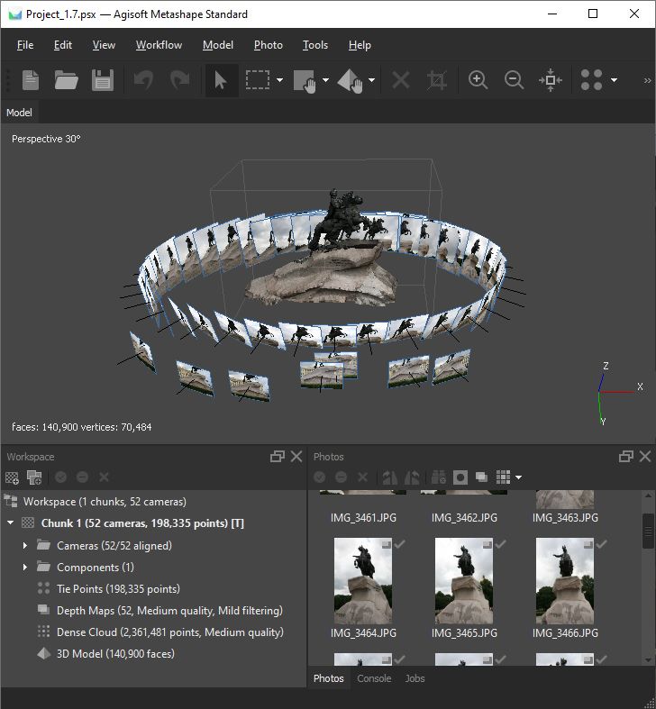
Alignment having been completed, computed camera positions and a sparse point cloud will be displayed.
You can inspect alignment results and remove incorrectly positioned photos, if any. To see the matches
between any two photos use View Matches... command from a photo context menu in the Photos pane.
Incorrectly positioned photos can be realigned.
To realign a subset of photos
1. Reset alignment for incorrectly positioned cameras using Reset Camera Alignment command from
the photo context menu.
2. Select photos to be realigned and use Align Selected Cameras command from the photo context menu.
3. The progress dialog box will appear displaying the current processing status. To cancel processing
click Cancel button.
When the alignment step is completed, the point cloud and estimated camera positions can be exported
for processing with another software if needed.
Image quality
Poor input, e. g. vague photos, can influence alignment results badly. To help you to exclude poorly
focused images from processing Metashape suggests automatic image quality estimation feature. Images
with quality value of less than 0.5 units are recommended to be disabled and thus excluded from
photogrammetric processing, providing that the rest of the photos cover the whole scene to be
reconstructed. To disable a photo use Disable button from the Photos pane toolbar.
Metashape estimates image quality for each input image. The value of the parameter is calculated based
on the sharpness level of the most focused part of the picture.
To estimate image quality
1.
Switch to the detailed view in the Photos pane using Details command from the Change menu
on the Photos pane toolbar.
2. Select all photos to be analyzed on the Photos pane.
3. Right button click on the selected photo(s) and choose Estimate Image Quality command from the
context menu.
4. Once the analysis procedure is over, a figure indicating estimated image quality value will be
displayed in the Quality column on the Photos pane.
Alignment parameters
15General workflow
"Align Photos" dialog
The following parameters control the photo alignment procedure and can be modified in the Align Photos
dialog box:
Accuracy
Higher accuracy settings help to obtain more accurate camera position estimates. Lower accuracy
settings can be used to get the rough camera positions in a shorter period of time.
While at High accuracy setting the software works with the photos of the original size, Medium setting
causes image downscaling by factor of 4 (2 times by each side), at Low accuracy source files are
downscaled by factor of 16, and Lowest value means further downscaling by 4 times more. Highest
accuracy setting upscales the image by factor of 4. Since tie point positions are estimated on the
basis of feature spots found on the source images, it may be meaningful to upscale a source photo
to accurately localize a tie point. However, Highest accuracy setting is recommended only for very
sharp image data and mostly for research purposes due to the corresponding processing being quite
time consuming.
Generic preselection
The alignment process of large photo sets can take a long time. A significant portion of this time
period is spent on matching of detected features across the photos. Image pair preselection option may
speed up this process due to selection of a subset of image pairs to be matched.
In the Generic preselection mode the overlapping pairs of photos are selected by matching photos
using lower accuracy setting first.
Reference preselection
The Estimated preselection mode takes into account the calculated exterior orientation parameters
for the aligned cameras. That is, if the alignment operation has been already completed for the project,
the estimated camera locations will be considered when the Align Photos procedure is run again with
the Estimated preselection selected.
16General workflow
When using Sequential preselection mode the correspondence between the images is determined
according to the sequence of photos (the sequence number of the image) it is worth noting that with
this adjustment, the first with the last images in the sequence will also be compared.
Reset current alignment
If this option is checked, all the tie, and key, and matching points will be discarded and the alignment
procedure will be started from the very beginning.
Additionally the following advanced parameters can be adjusted.
Key point limit
The number indicates upper limit of feature points on every image to be taken into account during
current processing stage. Using zero value allows Metashape to find as many key points as possible,
but it may result in a big number of less reliable points.
Tie point limit
The number indicates upper limit of matching points for every image. Using zero value doesn't apply
any tie point filtering.
Apply mask to
If apply mask to key points option is selected, areas previously masked on the photos are excluded
from feature detection procedure. Apply mask to tie points option means that certain tie points are
excluded from alignment procedure. Effectively this implies that if some area is masked at least on a
single photo, relevant key points on the rest of the photos picturing the same area will be also ignored
during alignment procedure (a tie point is a set of key points which have been matched as projections
of the same 3D point on different images). This can be useful to be able to suppress background in
turntable shooting scenario with only one mask. For additional information on the usage of masks
please refer to the Using masks section.
Exclude stationary tie points
Excludes tie points that remain stationary across multiple different images. This option enables
alignment without masks for datasets with a static background, e.g. in a case of a turntable with a
fixed camera scenario. Also enabling this option will help to eliminate false tie points related to the
camera sensor or lens artefacts.
Guided image matching
This option allows to effectively boost the number of keypoints per image as if the value of Key
point limit was straightforwardly increased, but without significant growth of processing time. Using
this parameter can improve results for images with vegetation (wooded terrain, grass, cornfields
and so on), spherical cameras and high resolution images (captured by professional grade cameras,
satellites or acquired by high-resolution scanning of the archival aerial images). To enable Guided
image matching, check corresponding option in Align Photos dialog and adjust Key point limit per
Mpx if needed. The number of detected points per image is calculated as (Keypoint limit per Mpx) *
(image size in Mpx). Small fraction will be extensively matched and used as guidance for matching
of remaining points.
Adaptive camera model fitting
This option enables automatic selection of camera parameters to be included into adjustment based on
their reliability estimates. For data sets with strong camera geometry, like images of a building taken
from all the sides around, including different levels, it helps to adjust more parameters during initial
camera alignment. For data sets with weak camera geometry , like a typical aerial data set, it helps
to prevent divergence of some parameters. For example, estimation of radial distortion parameters
for data sets with only small central parts covered by the object is very unreliable. When the option
is unchecked, Metashape will refine only the fixed set of parameters: focal length, principal point
position, three radial distortion coefficients (K1, K2, K3) and two tangential distortion coefficients
(P1, P2).
17General workflow
Note
• Tie point limit parameter allows to optimize performance for the task and does not generally
effect the quality of the further model. Recommended value is 4000. Too high or too low tie point
limit value may cause some parts of the dense point cloud model to be missed. The reason is that
Metashape generates depth maps only for pairs of photos for which number of matching points is
above certain limit. This limit equals to 100 matching points, unless moved up by the figure "10%
of the maximum number of matching points between the photo in question and other photos,
only matching points corresponding to the area within the bounding box being considered."
• The number of tie points can be reduced after the alignment process with Tie Points - Thin Point
Cloud command available from Tools menu. As a results sparse point cloud will be thinned, yet
the alignment will be kept unchanged.
Components
Some image subsets may be not aligned as the result of the Align Photos operation, if the sufficient amount
of tie points was not detected between such subsets. Such subsets which are not aligned with the main
subset will be grouped into individually aligned parts - Components.
The components into which the camera alignment have been split after the Align Photos operation will be
displayed in the chunk's contents of the Workspace pane inside the Components folder.
Incremental image alignment
In case some extra images should be subaligned to the set of already aligned images, you can benefit
from incremental image alignment option. To make it possible, two rules must be followed: 1) the scene
environment should not have changed significantly (lighting conditions, etc); 2) do not forget to switch on
Keep key points option in the Preferences dialog, Advanced tab BEFORE the whole processing is started.
To subalign some extra images added to the chunk with already aligned set of
images
1. Add extra photos to the active chunk using Add photos command from the Workflow menu.
2. Open Align photos dialog from the Workflow menu.
3. Set alignment parameters for the newly added photos. IMPORTANT! Uncheck Reset alignment
option.
4. Click OK. Metashape will consider existing key points and try to match them with key points detected
on the newly added images.
Point cloud generation based on imported camera data
Metashape supports import of external and internal camera orientation parameters. Thus, if precise camera
data is available for the project, it is possible to load them into Metashape along with the photos, to be
used as initial information for 3D reconstruction job.
To import external and internal camera parameters
1. Select Import Cameras command from the File menu.
2. Select the format of the file to be imported.
18General workflow
3. Browse to the file and click Open button.
4. The data will be loaded into the software. Camera calibration data can be inspected in the Camera
Calibration dialog, Adjusted tab, available from Tools menu.
Camera data can be loaded in one of the following formats: Agisoft (*.xml), BINGO (*.dat), Inpho Project
File (*.prj), Blocks Exchange (*.xml), Bundler (*.out), Autodesk FBX (*.fbx), VisionMap Detailed Report
(*.txt), Realviz RZML (*.rzml), Alembic (*.abc).
Once the data is loaded, Metashape will offer to build point cloud. This step involves feature points
detection and matching procedures. As a result, a sparse point cloud - 3D representation of the tie-points
data, will be generated. Build Point Cloud command is available from Tools - Tie Points menu. Parameters
controlling Build Point Cloud procedure are the same as the ones used at Align Photos step (see above).
Building dense point cloud
Metashape allows to create a dense point cloud based on the calculated exterior and interior image
orientation parameters.
Dense point cloud generation is based on depth maps calculated using dense stereo matching. Depth maps
are calculated for the overlapping image pairs considering their relative exterior and interior orientation
parameters estimated with bundle adjustment. Multiple pairwise depth maps generated for each camera
are merged together into combined depth map, using excessive information in the overlapping regions to
filter wrong depth measurements.
Combined depth maps generated for each camera are transformed into the partial dense point clouds,
which are then merged into a final dense point cloud with additional noise filtering step applied in the
overlapping regions. The normals in the partial dense point clouds are calculated using plane fitting to the
pixel neighborhood in the combined depth maps, and the colors are sampled from the images.
For every point in the final dense point cloud the number of contributing combined depth maps is recorded
and stored as a confidence value. This confidence value can be used later to perform additional filtering of
low confidence points using the Filter by Confidence... command from the Tools > Dense Cloud menu.
Metashape tends to produce extra dense point clouds, which are of almost the same density, if not denser,
as LIDAR point clouds. A dense point cloud can be edited within Metashape environment and used as
a basis for such processing stages as Build Mesh. Alternatively, the point cloud can be exported to an
external tool for further analysis.
To build a dense point cloud
1.
Check the reconstruction volume bounding box. To adjust the bounding box use the Resize
Region, Move Region and Rotate Region toolbar buttons. To resize the bounding box, drag
corners of the box to the desired positions; to move - hold the box with the left mouse button and
drag it to the new location.
2. Select the Build Dense Cloud... command from the Workflow menu.
3. In the Build Dense Cloud dialog box select the desired reconstruction parameters. Click OK button
when done.
4. The progress dialog box will appear displaying the current processing status. To cancel processing
click Cancel button.
19General workflow
Note
• More than one instance of Dense cloud can be stored in one chunk. In case you want to save
current Dense cloud instance and build new one in current chunk, right-click on Dense cloud and
uncheck Set as default option. In case you want to save current Dense cloud instance and edit its
copy, right-click on Dense cloud and choose Duplicate option.
Build Dense Cloud parameters
"Build Dense Cloud" dialog
Quality
Specifies the desired quality of the depth maps genration. Higher quality settings can be used to obtain
more detailed and accurate geometry, but they require longer time for processing. Interpretation of the
quality parameters here is similar to that of accuracy settings given in Photo Alignment section. The
only difference is that in this case Ultra High quality setting means processing of original photos, while
each following step implies preliminary image size downscaling by factor of 4 (2 times by each side).
Additionally the following advanced parameters can be adjusted.
Depth filtering modes
At the stage of dense point cloud generation reconstruction Metashape calculates depth maps for every
image. Due to some factors, like noisy or badly focused images, there can be some outliers among
the points. To sort out the outliers Metashape has several built-in filtering algorithms that answer the
challenges of different projects.
If there are important small details which are spatially distinguished in the scene to be
reconstructed, then it is recommended to set Mild depth filtering mode, for important features
not to be sorted out as outliers. This value of the parameter may also be useful for aerial projects
in case the area contains poorly textured roofs, for example. Mild depth filtering mode is also
required for the depth maps based mesh reconstruction.
If the area to be reconstructed does not contain meaningful small details, then it is reasonable
to choose Aggressive depth filtering mode to sort out most of the outliers. This value of the
parameter normally recommended for aerial data processing, however, mild filtering may be
useful in some projects as well (see poorly textured roofs comment in the mild parameter value
description above).
20You can also read