OWNERS MANUAL NORTH AMERICAN 60HZ - CANADIAN SPA COMPANY
←
→
Page content transcription
If your browser does not render page correctly, please read the page content below
Canadian Spa Company
             Owners Manual
          North American 60Hz

w w w. c a n a d i a n s p a c o m p a n y. c o m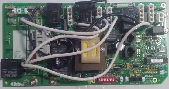
Owners Manual

                                 SAFETY INFORMATION - North America (60Hz)
IIMPORTANT SAFETY INSTRUCTIONS                                                                           9.    AUDIO/VIDEO EQUIPMENT WARNINGS (Optional equipment based on model)
When installing and using this electrical equipment be sure to follow these basic safety                       CAUTION: Risk of electrical shock. Do not leave compartment door open.
precautions:                                                                                             10.   CAUTION: Risk of electrical shock. Replace components only with identical
1. WARNING: To reduce the risk of injury, do not permit children to use this product                           components.
    unless they are closely supervised at all times.                                                     11.   WARNING: Prevent electrocution. Do not connect any auxiliary components (for
2. WARNING: A wire connector is provided on this unit to connect a minimum 8 AWG                               example cable, additional speakers, headphones, additional audio/video
    (8.4mm) solid copper conductor between this unit and any metal equipment,                                  components, etc.) to system.
    metal enclosure of electrical equipment, metal pipe, or conduit within 5 feet 		                     12.   The units with an AM / FM tuner are not installed with an outdoor antenna; if you
    (1.5m) of the unit.                                                                                        choose to install an outdoor antenna it should be installed in accordance with
3. DANGER: Risk of accidental drowning. Extreme caution must be exercised to                                   Article 810 of the National Electrical Code, ANSI/NFPA 70. The units contain an
    prevent unauthorized access by children. To avoid accidents, ensure that children                          internal antenna installed under the spa skirt.
    cannot use this spa unless they are supervised at all times.                                         13.   CAUTION: Risk of electrical shock. Do not service this product yourself as opening
4. DANGER: Risk of injury. The suction fittings in this spa are sized to match                                 or removing audio covers may expose you to dangerous voltage or other risk of
    specific water flow created by the pump. Should the need arise to replace 		                               injury. Refer all servicing to qualified service personnel.
    the suction fitting or the pump, be sure to that the flow rates are 			                              14.   CAUTION: Risk of electrical shock. When the power supply connections or power
    compatible. Never operate the spa if suction fittings are broken or missing.                               supply cord(s) are damaged; if water is entering the audio / video compartment
    Never replace a suction fitting with one rated less than the flow rate marked on 		                        or any electrical equipment compartment area; if the protective shields or barriers
    the original suction fitting.                                                                              are showing signs of deterioration; or if there are signs of other potential damage
5. DANGER: Risk of electrical shock. Install at least 5 feet (1.5m) from all metal 		                          to the unit, turn off the unit and refer the servicing to a qualified service personnel.
    surfaces. As an alternative, spa may be installed within 5 feet (1.5m) of 		                         15.   This unit should be subject to periodic routine maintenance (for example, once
    metal surfaces if each metal surface is permanently connected (bonded) by a 		                             every 3 months) to make sure that the unit is operating properly.
    minimum No. 8 AWG (8.4 mm) solid copper conductor attached to the wire 		                            16.   CAUTION: Do not operate audio video controls while inside the spa
    connector on the grounding lug, inside the equipment compartment on the 		                           17.   Installation of the spa for other than a residential dwelling will result in voiding
    equipment box.                                                                                             the manufacturer’s warranty.
6. DANGER: Risk of Electrical Shock. Do not permit any electrical appliance such 		                      18.   Do not bring any object into the spa that could damage the spa shell.
    as a light, telephone, radio, television, etc. within 5 feet (1.5m) of a spa unless 		               19.   Never insert any object into any opening.
    such appliances are installed and built-in by the manufacturer.                                      20.   WARNING: Do not sit on the spa cover or place objects on it.
7. ELECTRICAL SUPPLY: The electrical supply for this product must include a                              21.   Remove any water or debris that may collect on the spa cover.
    suitably rated switch or circuit breaker to open all ungrounded supply conductors                    22.   WARNING: Do not use the spa immediately after strenuous exercise.
    to comply with the national electrical standards. This disconnect must be readily                    23.   If you feel pain or dizziness at any time while using the spa, discontinue use and
    accessible and visible to the spa occupant but installed at least 5 feet 		                                contact a physician.
    (1.5m), from the spa water.                                                                          24.   WARNING: To reduce risk of injury it is especially important that persons with
8. WARNING: To reduce the risk of injury:                                                                      pre-existing health conditions or problems such as obesity, heart disease, high
a) The water in the spa should never exceed 40°C (104°F). Water temperature 		                                 or low blood pressure, circulatory problems, pregnancy or diabetes to consult
    between 38°C (100°F) and 40°C (104°) is considered safe for a healthy adult. 		                            their doctor before using the spa.
    Lower water temperatures are recommended for young children and when 		                              25.   WARNING: Observe reasonable time limits when using the spa. Long exposures
    the spa use exceeds 10 minutes.                                                                            at high temperatures can cause high body temperatures. Symptoms may include
b) Since excessive water temperatures have a high potential for causing fetal                                  dizziness, nausea, fainting, drowsiness, and reduced awareness. These effects
    damage during early months of pregnancy, pregnant women should limit spa 		                                could possibly result in drowning.
    water temperatures to 38°C (100°F)                                                                   26.   WARNING: The spa jets produce a stream of water with relatively high pressure.
c) Before entering a spa, the user should measure the water temperature with an 		                             Prolonged exposure of localized area of the body may cause bruises to the skin.
    accurate thermometer since the tolerance of water temperature regulating 		                          27.   IMPORTANT: The include warning sign must be posted where all users of the spa
    devices varies.                                                                                            can see and read it.
d) The use of alcohol, drugs, or medication before or during spa use may lead to 		                      28.   WARNING: To avoid risk of drowning. The spa cover should be in place and properly
    unconsciousness with the possibility of drowning.                                                          latched when spa is not in use.
e) Obese persons and persons with a history of heart disease, low or high blood 		                       29.   IMPORTANT: Read and understand the warnings on the spa cover.
    pressure, circulatory system problems, or diabetes should consult a physician 		                     30.   Proper water chemistry is necessary to maintain the water and prevent possible
    before using a spa.                                                                                        damage to spa components.
f) Persons using medication should consult a physician before using a spa since
    some medication may induce drowsiness while other medication may affect heart
    rate, blood pressure, and circulation.

                                                                                               WARNING
                                          REDUCE THE RISK OF ELECTROCUTION
                                          1. Never place an electric appliance within 5 feet (1.5m) of spa.

                                          REDUCE THE RISK OF CHILDREN DROWNING
                                          1. Supervise children at all times.
                                          2. Attach and lock down spa cover after each use.
                                          REDUCE THE RISK OF OVERHEATING
                                          1. Check with a doctor before use if pregnant, diabetic, in poor health, or under medical care.
                                          2. Exit immediately if uncomfortable, dizzy, or sleepy. Spa heat can cause hyperthermia and unconsciousness.
                                          3. Spa heat in conjunction with alcohol, drugs, or medication can cause unconsciousness.
                                          WHEN PREGNANT; soaking in hot water for long periods can harm your fetus. Measure water temperature before entering
                                          1. Do not enter spa if water is hotter than 100°F (38°C).
                                          2. Do not stay in spa for longer than 10 minutes.

                                                                                                    00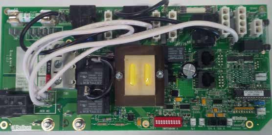
Owners Manual
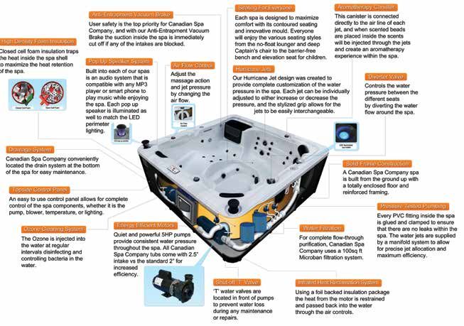
Introduction to your hot tub /spa
SPA SHELL: Surface of the spa that holds the water, constructed of JET: Device that ejects air and water, creating water movement in the
acrylic and fiberglass. spa.
SPA SKIRT: Surrounding material that conceals the underside of the AROMATHERAPY: A small canister that holds scented beads and
spa shell and equipment bay. Also referred to as the ‘spa cabinet’, works conjunction with the air control system to create an aromatic
‘cladding’ or ‘panels’. experience.
ACCESS PANELS: Removable sections of the spa skirt located on the DRAIN VALVE: Valve located on the outside of spa cabinet used to
operator side of the spa. The equipment bay, including pump(s) and drain water from the spa. A garden hose can be attached to the drain
spa controller are located behind the access panels. valve.
SPA CONTROLLER: Unit that controls spa operations, containing elec- EQUIPMENT BAY: Location under the spa shell covered by access
tronic programming boards, heater and all connections for Pump(s), panels that houses the spa controller and equipment.
Light(s), Ozone Generation Unit and Topside Console. Also referred to FILTER HOUSING: Assembly that holds the filter cartridge
as ‘Spa Pack’ or ‘Controller’. (Note: configurations may differ from model to model).
CIRCULATION PUMP: Small, energy efficient pump used for FLOATING WEIR: Telescoping device in the filter system that skims the
filtration and heating of the spa. water to collect floating particles.
MASSAGE PUMP: Electro-mechanical device to move water, FOOT WELL: Lowest portion of the spa where the suction fittings are
consisting of a wet end and a motor. located.
AIR BLOWER: Air pump used to add extra bubbles to the water stream. OVERLAY: Decal covering the Topside Console, showing button
The pump is connected electrically to the Spa Controller and is location for various spa operations.
controlled by the spa controller.
SUCTION FITTING: Located at the bottom of the spa, used to return
OZONE GENERATOR: Device that generates ozone to aid in water back into the filter and pump system.
maintaining water quality. Ozone helps eliminate organic material such
as body oils, dead skin cells and hair. AIR CONTROL: Device located on top side of spa used to turn on and
off air assist to the jets. One valve can operate up to 20 jets.
HEATER: Electrical resistance device located in the Spa Controller
containing the heating element and 2 temperature sensors. The flow WATER DIVERTER: Device located on top side of spa and used to
through heater heats the spa’s water as it flows across the heating change the direction of water flow within the space.
element. Heaters are available in several wattages. WATERFALL ON/OFF VALVE: Located on top rail of spa used to adjust
TOPSIDE CONSOLE: Button pad and temperature display panel the waterfall flow.
located on the top of the spa into which various commands, SLICE VALVE: Two-position (open or closed) sliding valve, used to cut
control sequences and options for operating the spa can be off water flow which allows for service to be preformed on the spa
input. User can set temperature, filtration cycle and heating mode equipment without the need to drain the spa. Slice valve operations:
through the console. Consoles have various shapes and button config- up for open, down (toward the valve body) for closed.
urations. Also referred to as the ‘Console’.
SPA COVER: Marine grade vinyl covering filled with rigid foam inserts
AIR INJECTOR: Small jet that pulls air from the Air Blower into spa jets. to cover the top of the spa. The spa cover is the most important item for
maintaining consistency of the spa water temperature and chemistry.
2
Owners Manual

                                                  How your spa functions
BASIC: Water is drawn through the drains in the foot well and the skim filter on the side of the spa it is then pumped through a filter, over the
heater, into the Ozone Reaction Chamber and returns to the jets. Finally the water entering the spa has now been filtered, heated and mixed
with air ready for use. Note: A sensor on the heater ensures water flow over the heater before allowing the heater to energize.

JETS: All regular jets can be flow adjusted by rotating the face of the jet. As the jet face is turned clockwise the water pressure will start to
decrease, and when turned counter-clockwise the water pressure will increase.

FILTER: A weir is located on the skimmer. It is used to skim oils and floating pieces of debris from the surface of the spa. (If applicable, the
weir should be facing in to the skimmer opening.)

AIR CONTROLS: Air Controls inject air into the jets via a venturi system. Rotating the left or right control from minimum to maximum activates
the air control.

NOTE: The system functions when your jets are at full power only.

                                           Spa operation - Filtration cycle

                                         Your spa exposed (Toronto model)*
               LED Pop-up speaker             Slice valves         LED Pop-up speaker                                              Shell insulation foam
                           1” Air pipe                                           5” Jet body                         2” Jet body
     Ozone

    Control
     pack

               Heater unions 2” water pipe                     2” Pump Pump             Water manifold 3” Jet body
                                                                union                                                                    Filtration housing
                                         2.5” Pump
                                           union
      Front access side of spa                                                                       Rear side of spa
                             * There may be slight differences/variations with each spa and that not every spa is exactly the same.

                                                                            3
Owners Manual

                                        Spa operation - Hot tub controls / Jets
                                                              Spa operation - Jets

HOW JETS WORK
Air is mixed with the water by using the air controls to create massage(s) of varying degrees. Water flow is adjusted by simply turning the
outer face of the full sized jets. Our hot tubs have a combination of pulsating, rotating, and directional adjustable jets.

              2” Directional jet                                   5” Massage jet                                    Large Diverter
              Adjustable and interchangeable jet features a        Adjustable and interchangeable jet features       Located on the topside of the spa, this valve
              directional nozzle. The jet can be removed by        an internal spinner to deliver a low pressure     physically diverts the flow of water from one
              turning it counter-clockwise. To replace the         soothing massage. The jet can be removed          jet zone of the spa to the other.
              jet push inward and clockwise until it clicks        by turning it counter-clockwise. To replace
              into place.                                          the jet push inward and clockwise until it
                                                                   clicks into place.

              2” Twin Roto jet                                     5” (Jumbo) Directional jet                        Air Controller
              Adjustable and interchangeable jet spins             Adjustable and interchangeable jet features       These are located around the top of your
              and pulsates. The jet can be removed by              a directional nozzle. The jet can be removed      spa. Increase or decrease the force of your
              turning it counter-clockwise. To replace the         by turning it counter-clockwise. To replace       jets by opening or closing the air control
              jet push inward and clockwise until it clicks        the jet push inward and clockwise until it        valves.
              into place.                                          clicks into place.

              2” Point jet                                         Circ Jet                                          Waterfall control
              Standard jet is permanently on and supplies          Supplies Ozone and heated water from the          Located on the topside of the spa, this valve
              heated water continually. The jet can be             circulation pump.                                 adjusts water flow to the waterfall.
              removed by turning it counter-clockwise. To
              replace the jet push inward and clockwise
              until it clicks into place.

              3” Directional jet                                   Air Jet (pepper pot)                              Aroma basket cap
              Adjustable and interchangeable jet features          Linked to the blower to inject air into the spa   Open cap to place aromatherapy beads.
              a directional nozzle. The jet can be removed         for an invigorating massage.                      Close after use.
              by turning it counter-clockwise. To replace
              the jet push inward and clockwise until it
              clicks into place.

              3” Massage jet
              Adjustable and interchangeable jet which
              spins to deliver a soothing massage. The jet
              can be removed by turning it counter-
              clockwise. To replace the jet push inward
              and clockwise until it clicks into place.

                                                                               4
Owners Manual

                                              Locating your hot tub/spa
                                                                               OUTDOOR LOCATION
                                                                               Considerations for selecting an outdoor spa location:
                                                                               • Proximity to the power source (long length of cable can be
                                                                                  expensive)
                                                                               • Local building and home owner association codes pertaining to
                                                                                  the installation of a portable spa
                                                                               • Do not place your spa within 10 ft (3m) of overhead power lines.
                                                                                  Make sure the spa is positioned so that access to the
                                                                                  equipment compartment and all side panels will not be blocked.
                                                                                  Be certain that your installation will meet all relevant local and
                                                                                  national safety codes and requirements.
                                                                               • How you intend to use your spa will help you determine where
                                                                                  you should position it. If your spa is mainly used for family
                                                                                  recreation be sure to leave plenty of room around it for activity.
                                                                                  If you will use it for relaxation and therapy, you’ll probably want to
CHOOSING A LOCATION                                                               create a specific mood around it.
This spa is designed for indoor or outdoor use. Factors to consider            • If you live in a region where it is cold or rains frequently, place the
when choosing a location for the spa include: weight of the spa,                  spa near a house entry point.
indoor/outdoor location and drainage. The following section provides           • In a cold-weather climate, bare trees will not provide much
guidelines that must be followed. It is the sole responsibility of the            privacy. Think of your spa’s surroundings during all seasons to
spa owner to ensure proper installation of the spa.                               determine your best privacy options. Consider the view of your
                                                                                  neighbours when you plan the location of your spa.
IMPORTANT: The base upon which the spa is placed must be                       • Prevent dirt and contaminants from being tracked into your spa
smooth, flat, level and capable of uniformly supporting the combined              by placing a foot mat at the spa’s entrance where the users
weight of the spa, water and users, without shifting or settling, for             can clean their feet before entering your spa. You may also
the entire time the spa is in place. If the spa is placed on a surface            consider keeping a small water-filled basin nearby for users to
which does not meet these requirements, damage to the spa skirt                   rinse their feet before enter your spa.
and/or Spa Shell may result. Damage caused by improper support is              • Adequate space for spa with accessibility for service (Clearance
not covered by the manufacturer’s warranty. It is the responsibility of           of 3 ft (1m) around the spa is recommended to permit servicing
the spa owner to ensure the integrity of the supporting structure at all          the unit)
times. SPA BASE: We recommend a poured, steel reinforced concrete              • Proper structural support is critical. Consult a licensed
slab with a minimum thickness of 4 inches (10cm). Wood decking is                 professional Structural Engineer to determine if the foundation
acceptable if it is constructed so that it meets the structural                   will adequately support the spa during the entire time it will be in
requirements outlined above.                                                      place, especially if the spa is to be placed on a deck, balcony, roof
                                                                                  or other platform not specifically tied into the main structural
The spa location must provide drainage away from the spa. Placing                 support.
the spa in a depression without provisions for proper drainage could           • Drainage: The area in which the spa is placed must have
allow rain water, snow melt, overflow and other casual water to flood             adequate drainage to handle the entire water content of the spa.
the equipment bay, creating a wet condition in which the spa could                In the event of spillage, areas around the spa may become wet;
be damaged. For spas recessed into a deck, installation must permit               therefore, all flooring, furniture, walls and adjacent structures
access to the spa access panels, either from above or below for                   should be able to withstand or resist water and moisture.
servicing. Ensure that there are no obstructions which would prevent           • Pathway to and from the spa (free of debris, dirt and leaves as
removal of all access panels and access to jet components,                        not to be tracked into the spa)
especially on the side of the access panels (typically under the               • Closeness to trees and shrubbery (leaves and birds create extra
Topside Console).                                                                 cleaning)
                                                                               • Sheltered environment (less wind and weather exposure results
WEIGHT CALCULATIONS: See spa specifications for exact weights.                    in lower operating and maintenance costs)
Typically the dry weight of a spa can range from 600-1000 lbs (US)             • Proximity to a changing area and shelter (especially in cold
(220-455 kg) dry. The volume of the spa can range from 300-400                    weather)
gallons US (1135-1515 litres).                                                 • Environmental factors such as rain, wind, snow and sunlight (run
                                                                                  off water, as from an unguttered roof overhang, shortens the
                                                                                  life expectancy of the spa cover)
                                                                               • Accessibility to children (you should be able to monitor the use
                                                                                  of the spa from the home to prevent unauthorized use by
                                                                                  children; you may want to enclose the spa with a fence or a self
                                                                                  latching gate to prevent unauthorized use)
                                                                               • Cover lift clearance (if you will be installing a cover lift as an
                                                                                  add on feature, allow 3ft (1m) on all sides of the spa)

                                                                           5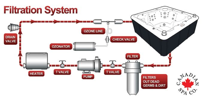
Owners Manual

                                                 Locating your hot tub/spa
INDOOR LOCATION                                                                   C) Location & Base:
Considerations for selecting an indoor spa location:                              A sheltered environment can result in lower operating and
• Local building codes for indoor installation of a portable spa                  maintenance costs. You must allow for 3 ft (1 m) of clearance for
• Adequate space for spa with accessibility for service (Clearance                access to the spa’s access panel for servicing.
   of 3 ft (1m) around the spa is recommended to permit servicing 		              • The site you select for your spa MUST be a flat, level continuous
   the unit)                                                                          surface that fully contacts the bottom of the spa.
• Proper structural support is critical. Consult a licensed 		                    • Your new spa weighs between 600-1000 lbs US (220-455 kg)
   professional Structural Engineer to determine if the foundation 		                 when dry, and when filled to capacity weighs 300-400
   will adequately support the spa during the entire time it will be in               gallons US (1135-1515 litres). Therefore a solid support is
   place, especially if the spa is to be placed on a second story or                  essential when the spa is mounted on a deck or ground level
   higher, balcony, roof or other platform not specifically tied into the             patio/floor. We recommend that you install your spa at ground
   main structural support.                                                           level. This allows for easy access to equipment.
• Proper ventilation: Consult an Engineer or authority who                        • A 4 inche (10cm) thick re-enforced concrete slab is ideal, but
   understands the necessary provisions to vent moist or heated air                   not essential. In most cases your spa can be placed on properly
   and air with chemical odours. When the spa is in use                               installed existing patios.
   considerable amounts of moisture escapes, potentially causing 		               • The base must be at least the size of the bottom of your spa (see
   mould and mildew which can damage certain surfaces and                             dealer for current sizes).
   surroundings.                                                                  • Water should always drain away from the spa. DO NOT locate
                                                                                      your spa in a low run-off area since melting snow or rain could
POSITIONING YOUR HOT TUB/SPA                                                          flood the area and cause pump and equipment damage.
                                                                                  • DO NOT situate the spa near or under overhead wires and keep
When selecting a site for your spa, take into account the following:
                                                                                      clear of all electrical appliances.
A) Local Codes:
There may be certain restrictions and/or requirements that are
particular to your locality. If in doubt, check with your local council.
B) Delivery Passageway:
The spa will arrive as a unit, and cannot be disassembled. Ideally
the spa will be placed on a dolly, either on its side or on its base. The
unit will then be rolled into place easily crossing grass, gravel, and
small terrain anomalies. For safe and non-intrusive installation, we
require an opening not less than the width of your spa (see dealer for
current sizes) plus at least 1 ft (30.5cm) in height for the dolly and a
minimum of 5 inches (12.7cm) clearance on each side for adequate
access. If your access does not meet these conditions, or in the case
of other obstacles (steps, fences, walls, steep hills, etc.) contact
Canadian Spa Company for advice and conditions.

                                                                              6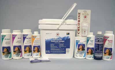
Owners Manual

                                                      Installation & Setup
PRE-DELIVERY SETUP
A standard Canadian Spa Company hot tub will be delivered to your curb, standing on its side and securely strapped to a pallet (the
swim spa models will arrive via flatbed truck). Ensure that you will have sufficient means to move your spa to your desired location
(dolly, forklift, crane etc). The spa cannot be disassembled and will require sufficient clearance to move it (refer to table below for spa
dimensions).
For Swim Spa owners: Your spa will arrive as a single unit on a flatbed truck and will require a crane or other mechanical method of unloading
to get the spa to your location. We recommend that you hire a professional lifting company to assess the situation and organise the move for
you. Canadian Spa Company will not take any responsibility for moving the spa because the spa warranty does not cover damage incurred
from unloading. We recommend a 6” (15cm) re-enforced concrete pad as a suitable base for your swim spa.
Failure to properly locate your spa may void your warranty, please contact your local Canadian Spa Company Dealer if you have any questions.

           Spa Model			Dimensions		Dry Weight		Filled Weight
           Yukon Plug & Play 79” x 40” x 30” 		                                   310lb			 1,310lb
           					200cm x 100cm x 74cm                                              140kg			595kg
           Quebec Plug & Play		 79” x 59” x 32”		                                 550lb			 1,970lb
           					200cm x 150cm x 80cm                                              250kg			890kg
           Winnipeg Plug & Play		 79” x 79” x 32”		                               690lb			 2,650lb
           					200cm x 200cm x 80cm                                              310kg			1,200kg
           Toronto				84” x 84” x 33”		840lb			3,000lb
           					213cm x 213cm x 82cm   380kg			1,360kg
           Thunder Bay			87” x 87” x 34”		880lb			3,475lb
           					220cm x 220cm x 85cm      400kg			1,575kg
           Niagara				90” x 90” x 39”		1,200lb			4,235lb
           					228cm x 228cm x 99cm   544kg			1,920kg
           Vancouver			90” x 90” x 35”		1,015lb			4,235lb
           					228cm x 228cm x 87cm    460kg			1,920kg
           Victoria				87” x 87” x 34”		880lb			3,595lb
           					220cm x 220cm x 85cm    400kg			1,630kg
           Alberta				83” x 83” x 34”		815lb			3,350lb
           					211cm x 211cm x 85cm   370kg			1,520kg
           Halifax				84” x 64” x 34”		660lb			2,490lb
           					213cm x 160cm x 85cm   300kg			1,130kg
           Montreal				84” x 64” x 34”		660lb			2,335lb
           					213cm x 160cm x 85cm    300kg			1,060kg
           St Lawrence 13’ Sport Pool		             154” x 90” x 54”		            2,200 lb			15,000
           					                                    390cm x 230cm x 140cm         998 kg			  6,804 kg
           St Lawrence 16’ Swim Spa		 197” x 90” x 54”		                          2,515lb			 16,975lb
           					500cm x 230cm x 140cm                                             1,140kg			7,700kg

                                                                          7
Owners Manual

                                       Installation: Electrical requirements
Electrical Installation NORTH AMERICA 60HZ
Spa Model			                       Voltage requirement                       Minimum GFCI Size             Minimum AWG
                                                                                                                              Refer to this table for the
Yukon Plug & Play			110V			N/A			N/A                                                                                          electrical requirements of your
Quebec Plug & Play		110V			N/A			N/A                                                                                          Canadian Spa hot tub.

Winnipeg Plug & Play		110V			N/A			N/A                                                                                        Do not use an electrical
                                                                                                                              extension cord to install any
Toronto				220V			50A			#6                                                                                                    Canadian Spa hot tub.
Thunder Bay			220V			50A			#6
                                                                                                                              The GFCI (ground fault circuit
Niagara				220V			50A			#6                                                                                                    interrupter) must be installed
                                                                                                                              according to the pictures below.
Victoria				220V			50A			#6
Alberta				220V			50A			#6
Halifax				220V			50A			#6
Montreal				220V			50A			#6
St Lawrence 13’ Sport Pool		220V			60A			#6
St Lawrence 16’ Swim Spa		220V			60A			#6

Canadian Spa Company requires that the electrical installation of your             IMPORTANT: The electrical wiring of this spa must meet the
hot tub is carried out by a professionally licensed electrician and that           requirements of any applicable local codes. The electrical circuit
all local electrical and building codes are adhered to.                            must be installed by a qualified electrician and approved by a local
                                                                                   building/electrical inspection authority.
Access to the electrical pack can be found by removing the panel
                                                                                   1. This spa must be permanently connected (hard wired) to the
directly below the topside control.
                                                                                      power supply. No plug-in connections or extension cords are to
                                                                                      be used in conjunction with the operation of the spa.
CONNECTING HOT TUB TO GFCI AND MAIN PANEL:
                                                                                      Supplying power to the spa which is not in accordance with
• All hot tubs must be wired with the appropriate sized wiring.                       these instructions will void both the independent testing agency
  Failure to do so will cause equipment damage and will not be                        listing and the manufacturer’s warranty.
  covered by your warranty
                                                                                   2. The power supplied to this spa must be a dedicated circuit with
• All hot tubs must be protected with a appropriately sized GFCI                      no other appliances or lights sharing the power provided by the
  in the consumer panel. Have your electrician verify using                           circuit.
  the diagram below                                                                3. To determine the proper wire size, see Electrical Requirements
                                                                                      section.
ITEMS NEEDED TO HELP COMPLETE ELECTRICAL CONNECTION:                                  a) Wire size must be appropriate as per local codes.
GFCI Breaker, electrical cable (check length and width for amperage                   b) All wiring must be copper to ensure proper connections. Do
and distance), cable gland, clips.                                                    not use aluminum wire. Using aluminum wire will void the
                                                                                      manufacturer’s warranty.
                                                                                   4. Although not required, a suitably rated isolator switch is
                                                                                      recommended for accessibility.
                                                                                   5. The electrical circuit supplied for the spa must include a suitable
                                                                                      Ground Fault (GFCI) having a rated residual operating
                                                                                      current not exceeding 30 mA.
    1. Consumer Panel       2. Outside isolation   3. Hot tub Control box
     (GFCI Protected)             switch                                           IMPORTANT: For supply connections, use conductors sized on the
                                                                                   basis of amperage but rated for 75°C (167°F).
ELECTRICAL WIRING PLAN (NORTH AMERICA)                                             6. An GFCI breaker must be used in order for the spa to function
                                                                                       properly.
                                                                                   7. To gain access to the spa’s power terminal block, remove the
                                                                                       screws to the access panel located under the Topside Console.
                                                                                       Remove the cover to the spa controller.
                                                                                   8. Feed the supply power cable through the side of the spa or from
                                                                                      underneath the unit. Use the appropriate cable gland to secure
                                                                                      the power supply.
                                                                                   9 Connect the wires, colour to colour on the terminal block.
                                                                                     TIGHTEN SECURELY (all wires must be connected securely or
                                                                                     damage could result).
                                                                                   10. After connecting your the electrical connection close the spa
                                                                                       control box cover and replace the spa access panels.
                                                                               8
Owners Manual

                                  Installation: Electrical requirements
VS501z Circuit Board (Toronto, Winnipeg, Halifax, Montreal, Yukon, Quebec)
                                                                             CIRCUIT BOARD CODES:
                                                                             E = 1 x Earth Screw
                                                                             S = 6 x Standard Screws
                                                                             H1 = Heater Connection ‘1’
                                                                             H2 = Heater Connection ‘2’
                                                                             SA = Sensor Port ‘A’
                                                                             SB = Sensor Port ‘B’
                                                                             J1A = Topside Port ‘1’ -RJ Type plug
                                                                             (phone connector)
                                                                             J2A = Topside Port ‘2’ -RJ Type plug
                                                                             (phone connector)

                                                                             JUMPER:
                                                                             J91 = Jumper on 1 pin enables Real
                                                                             Time Clock function (ML900), Jumper
                                                                             on 2 pin disables RTC function

VS515Z Circuit Board (Alberta, Niagara, Thunder Bay, Victoria, Vancouver)
                                                                             CIRCUIT BOARD CODES:
                                                                             E = 1 x Earth Screw
                                                                             S = 7 x Standard Screws
                                                                             H1 = Heater Connection ‘1’
                                                                             H2 = Heater Connection ‘2’
                                                                             SA = Sensor Port ‘A’
                                                                             SB = 2 x Sensor Port ‘B’
                                                                             T-Pad 1/2/3 = Topside Ports 1, 2 & 3
                                                                             (Molex Connector)

                                                                             JUMPER:
                                                                             J91 = Jumper on 1 pin enables Real
                                                                             Time Clock function (ML900), Jumper
                                                                             on 2 pin disables RTC function

                                                                 9
Owners Manual
Installation: Electrical requirements
ELECTRICAL REQUIREMENTS FOR SWIM SPA We recommend you book a contract lift where the lifting company
will assess the situation and method of the lift and carry insurance in
Your swim spa runs on 220V 60Hz. There are two configurations you case of accidental damage to the spa or the property. The spa
can run your swim spa on. warranty does not cover damage from installation. It is the
responsibility of the customer or his agents be it crane company or
The minimum supply current is 60 Amps, in this configuration the lift operator to assess the lift and control all aspects of moving the
heater will disengage if all 4 pumps are turned on. spa. Canadian Spa Company will not take responsibility for any part
of moving the spa, and cannot advise on the methods used to move
The second option is to have the heater on even when the spa is the spa.
running at full speed; in very cold climates this may be desirable
especially if using the spa outdoors in winter continually. In this Base
configuration a 60 Amp supply is required. The base for your swim spa must be a flat level surface that contacts
the entire base of the spa. We recommend 6 inches (15 cm) of
The size of the wire required will be determined by the distance to re-enforced concrete but any flat level base that is stable and will not
the supply and the shielding method; your electrician will be able to shift or settle will suffice. If sinking your spa into the ground you need
advise you of the required wiring for your specific situation. to provide adequate drainage for water so that the hole the spa sits in
cannot flood as this will damage the electronics and electrical
Access components. Also at least 3ft (1 metre) of access to the entire front of
The swim spa will arrive assembled as a single unit on a pallet. It the spa filters is required for component access. You are responsible
will weigh approximately 2000-2500lb (depending on the model) for providing adequate access in order to repair the spa in case of
and cannot be disassembled. For this reason you will need to have a fault.
crane or other mechanical method of unloading the spa and getting it
to your chosen site.
EL2000 Circuit Board (St Lawrence 13’ and 16’ Swim Spa)
CIRCUIT BOARD CODES:
E = 1 x Earth Screw
S = 7 x Standard Screws
H1 = Heater Connection ‘1’
H2 = Heater Connection ‘2’
SA = Sensor Port ‘A’
SB = Sensor Port ‘B’
T-Pad 1/2/3 = Topside Ports 1, 2 & 3
(Molex Connector)
JUMPER:
J8 = Jumper on 1 pin when using 2kW
or 1kW Heater. Jumper on 2 pin when
using 3kW Heater
J91 = Jumper on 1 pin enables Real
Time Clock function (ML900), Jumper
on 2 pin disables RTC function
Expander Board - 55026: for pump
3 & 4 (split plug)
10Owners Manual
Starting your hot tub/spa
Filling the spa through the filter housing preventsan air lock from
occurring in the spa pumps, which is an air pocket preventing the flow
of water through the pump. Permanent damage caused by running the
pump with an air lock (or without water) is not covered by the
manufacturer’s warranty.
10. Check for leaks! Although spas are fully checked at the factory,
shipping and delivery might cause a leak.
11. Before power is applied familiarise yourself with the spa
control operations.
12. Adding some Scale Control during the filling process reduces
limescale. Follow package instructions.
13. Turn water off and remove hose.
14. Reinstall filter cartridge, basket and filter lid.
15. Add start-up Chemicals after power is turned on. Refer to
Powering Up the Spa section.
FILLING UP YOUR HOT TUB/ SPA
IMPORTANT: Before filling the spa, it is important to read and
understand the water chemistry section of this manual. Do not
proceed until the water chemistry section is understood and the source
water is tested.
Verify that the spa is in the desired final location. Refer to the
‘Choosing a Location’ section - once filled, the spa cannot be moved
without draining.
Follow these filling instructions to avoid damage to the spa pumps:
1. Leave power to the spa off until spa is completely filled.
2. Never leave an unfilled spa exposed to direct sunlight without the
Spa Cover installed. Resulting damage such as bubbles and
wrinkles in the spa shell and fading of the jet faces is not DRAINING YOUR HOT TUB/ SPA USING THE DRAIN VALVE
covered by the manufacturer’s warranty.
1. Start by shutting off the electrical breaker connected to your spa
3. Never operate spa pumps without water because this could result
in permanent pump and/or heater damage which is not covered 2. Open the drain valve located at the side of the spa and let the
by the manufacturer’s warranty. water drain out. This valve has a straightforward locking
mechanism that stops the water from flowing out while you
4. Remove all warning labels from spa shell. attach a garden hose to the cap.
5. Apply Acrylic Surface Protection solution if desired to keep the
spa shell clean, especially around the water line. Follow package 3. With the valve extended, unscrew the cap from the middle of the
instructions. valve.
6. Remove the filter lid, basket and filter cartridge. 4. Screw in the male end of the garden hose to the valve and run
the hose to your drain location. When ready, push the valve back
7. Inspect all Jets (shipping may cause jets to become loose or in and twist it to empty the water from the spa.
detached). Check to see that the black Drain Valve (located to
the left or right of the front access panel) is closed and that all 5. Once the water has stopped flowing out of the drain valve, use
barrel unions are tight. The slice valves should be open. the wet/dry vacuum to suck out any remaining water from each
jet head (NOTE: If your spa is equipped with a blower, briefly turn
IMPORTANT: Follow the next steps closely to prevent damage to the power to the spa back on and run the blower for 10 seconds
the Spa Pumps. to remove excess water. Shut off the power when finished).
8. Insert garden hose or other clean water source directly into 6. Twist valve and pull out to CLOSE.
filter housing. Push hose pipe into filter housing until it stops.
Fill up to bottom of the LED lights. Secure hose placement and
turn on water.
11Owners Manual
Starting your hot tub/spa
POWERING UP YOUR SPA
Once the spa is properly wired and filled with water, the spa power can
be turned on and Start-up chemicals added.
1. Turn on GFCI breaker. If breaker trips immediately check
wire connections. Upon initial power up, 4 sets of numbers flash
on the LED display of the topside Console. The last number in the
sequence is the incoming power meter which can be used to verify
that the spa is wired correctly.
2. The spa begins an automatic priming routine which will last 5
minutes (“Pr” is on the LED display).
3. The priming routine will automatically run each spa pump to
prime. When the “Pr” is displayed, press any PUMP button
to prime that pump or wait for the priming routine to turn
on the Pump. IMPORTANT: To avoid pump damage, do not run
pumps for more than 1 minute without moving water. If no water
is moving, turn the power off and perform air lock procedure.
4. The Topside Console display flashes “100F” then“--F” for
approximately 2 minutes to determine water temperature as it
flows through the heater.
5. The default pre-set temperature is 100F The last measured
temperature is constantly displayed on the LCD readout. This
temperature will be current only when the pump has been
running for at least 2 minutes. Set the desired temperature
between 80-104°F (26- 40°C) by pressing the temp button(s).
If the water temperature is below the set temperature, the spa’s
heater and heat indicator light will turn on. All features of
the Topside Console will be available. The spa will heat
approximately 1° every 30 minutes per 1,000 litres.
6. Check for leaks! Although spas are fully checked at the factory,
shipping & delivery might cause a leak. Remember to pay
particular attention to barrel unions adjoining the heater.
Contact your Canadian Spa dealer directly if there is a problem.
If your new spa pump does not prime (flow) on the initial start-up you
may be experiencing an “air lock”. The above photograph refers to plug and play models only
This normal occurrence can be easily corrected by loosening the
plumbing union on the suction side of the Jet or Circulation Pump until
water flows into the pump and all air is expelled.
PRESS BUTTONS SLOWLY FOR FIRST RUN WHEN STARTING UP
ONCE PR EXITS, SET TEMPERATURE ON SPA (SEE SPA OPERATION
SECTION FOR DIFFERENT SPA TOPSIDES)
12Owners Manual
Installation: Adding your spa cover
ATTACHING YOUR SPA COVER TOP MOUNT HOT TUB COVER LIFTER
The Spa Cover is an important accessory to help preserve the spa’s Fully compatible with ALL our Canadian Spa hot tubs and spas and
temperature. The Spa Cover also serves as a safety device, preventing most other brands; this Cover Lifter is the ideal choice to
unauthorized users from entering the spa. Proper installation of the Spa complement your Hot Tub, making cover removal and replacement a
Cover is an important addition in the spa installation. quick, one-handed operation and reducing wear and tear.
1. Remove Spa Cover from packaging. • Low-profile design
2. Place Spa Cover on spa in order to allow easy access to the • Virtually zero clearance
topside console when opening the cover. required behind spa – great for tight spaces (particularly if your
3. Line up attaching straps and secure with mounting hardware. spa is located in a gazebo)
4. Use locking mechanism to lock Spa Cover in place. • Mounts directly to the spa
• Fits up to 96”(2.4m) Spas
IMPORTANT: • Made of Aluminium
• Always lock Spa Cover in place when not using the spa.
• Do not walk or sit on Spa Cover.
• Remove snow build-up to avoid breaking the foam inner core.
• Do not drag Spa Cover on rough surfaces.
Like any luxury item - a boat, car or recreational vehicle, care and
maintenance is critical to the lasting quality and enjoyment of a spa.
The spa has been designed to provide years of health and relaxation
benefits. Proper care and maintenance outlined in this section is
necessary to ensure the longevity of the spa. Damage caused by
not following care and maintenance guidelines in this section is not
covered by the manufacturer’s warranty.
CANADIAN SPA CABINET MOUNT LIFTER.
Fully compatible with Canadian Spa Company spas; this cover lifter
is the ideal choice to complement your hot tub or spa, making cover
removal and replacement a quick, one-handed operation while
reducing wear and tear on your hot tub cover.
• Mounts directly to the spa cabinet
BOTTOM MOUNT • Made of black powder-coated Aluminum
HOT TUB COVER LIFTER. • Fits up to 96” (2.4m) Spas (including swim spa)
• Requires 12”-18” (31cm - 46 cm) rear clearance
Fully compatible with Canadian
Spas; this Cover Lifter is the Whilst this is the most suitable product to complement our hot tub
ideal choice to complement range, this product will also fit most regular shaped hot tubs and
your hot tub or spa, making spas up to 96” (2.4m) wide.
cover removal and replacement
a quick, one-handed operation NOTE: This product requires some tools to assemble and fit,
while reducing wear and tear on your hot tub cover. including: a spanner and a cordless drill.
• Mounts directly to the spa
• Can be mounted with optional under-spa brackets without the
need for drilling holes in the skirt.
• Made of black powder-coated Aluminum
• Fits spas up to 96” (2.4 m.)
• Requires 12”-18”(31cm - 46 cm) rear clearance
13Owners Manual
Spa operation - Azure i212 CS Control Panel
Welcome To A New Dimension In Spa Control Systems. Except the Option 2 and Option 3 Buttons can be used to Navigate
and Select from the Menu System.
Quick Start Guide - You can use your Smart Control two ways: • The Up Button Scrolls Up in the Menu Screens.
(1) Home Page Single Touch Button Control to turn a function On or
• The Down Button Scrolls Down in the Menu Screens.
Off, like a Pump, Light, or Mood, without any navigation or additional
steps. (2) Navigation Mode where you utilize the full opportunities on • The Left Button Moves Left from Settings to the next Icon
the Full Color Screen to Setup and Control your Spa. In Navigation Function Left, and Exits Back to the Previous Menu when you are
Mode, you can immediately return to the Home Screen by Touching in a Menu.
the Back Home Button, or automatically return to the Home
Screen in a few seconds. • The Right Button Moves Right from Settings to the next Icon
Function Right, and Moves Right to the Next Menu when you are in
This Section of the Control Panel User’s Manual is intended to be a a Menu.
Quick Start Guide to get you started in Navigating the Azure i212 CS • The Select Button is used to Select a Menu Item, or turn an
Control Panel Menu System.
item On or Off.
Home Screen System Control • The Back Home Button is used to Return to the Home Screen.
• To use the Light , Temp , Volume , and Pump
Buttons to ControlSpa Equipment and Functions. you must Return to
the Home Screen.
When Navigating the Menus, if the Yellow
Highlighted Menu Bar you are on has an
This is the Home Screen with Canadian Spa Company Logo (Left) Arrow at the Right End of the Menu Bar,
These are the System Control Touch Buttons that are active from the use the Right Button to Navigate to the
Home Screen (Right) Next Menu, and use the Left Button to Return to the Previous Menu.
Use the Up Button to Scroll Up to the next Menu Bar Above, or use the
When the Home Screen is Displayed, all of the buttons Except the Down Button to Scroll Down to the next Menu Bar Below.
Back Home Button can be used to Directly Control the Spa Sys-
tem equipment and other functions. The Icons on the bottom of the If the Blue Area at the Bottom of the Menu
Screen indicate that the Functions are turned On, or are Active. says More and has Arrows pointing Down
and/or Up, as indicated, use the Down
• The Pump Button is the Jet Pump Control Button. In a 2 Button to Scroll from the Bottom Menu Bar to the Next Menu, or the
Pump System, it is the Jet Pump 1 Control Button. Up Button to Scroll from the Top Menu Bar to the Previous Menu.
• The Light Button is the Spa Light Control Button.
Powering Up Your Spa Control System
• The Temp Button is the Water Temperature Control Button. This Section of the User’s Manual provides Detailed Instructions for
• The Volume Button is the Audio Volume Control Button. properly and Safely Powering Up your Spa Control System. Before
• The Option 2 Button Opens the Help Navigation Menu. In a 2 you turn ON the Power to your Spa Control System, make sure that
Pump System, it is the Jet Pump 2 Control Button. the Spa Water Level is at the Spa Manufacturer’s Minimum required
Operating Water Level.
• The Option 3 Button Opens the Settings Navigation Menu. In
a 2 Pump System, it is the Air Blower Control Button. First turn ON the Branch Circuit Breaker Protecting the Spa and
• The Select Button Changes from the Home Screen to Control System, and then turn ON the GFCI Protecting the Spa
and Control System.
Navigation Mode.
Navigation Mode System Control
It will take 3 to 4 minutes for the Software to Load and Control
System to Initialize. After the Power is ON, the Control Panel Button
Backlighting will turn ON, but the Display Screen will remain Black
for about 20 seconds. Then, for the next 20 seconds, there will be a
The Settings Icon on the Navigation Screen is Highlighted (Left)
Screen that shows the Serial and Part Numbers. At about 40 seconds
These are the Navigation Mode Active Navigation Buttons.(Right)
after the Power is ON, there will be a Screen indicating that the
Software is Loading.
In Navigation Mode, at the Center of the Screen, all of the Icon
Functions can be Scrolled either Left or Right to access any of the
Icon Functions, with the Icons rotating like a wheel. All the ButtonsOwners Manual
Spa operation - Azure i212 CS Control Panel
The Spa Light is ON, or the Optional LED Spa Lights are ON.
Jet Pump 1 is On at LOW Speed.
Jet Pump 1 and Jet Pump 2 are On at HIGH Speed.
Air Blower is ON.
The four White Progress Dots at the Bottom of the Screen will
advance about every minute until all four Dots are Red. The Ozone Generator is ON.
Setting Up Your Spa Control System
This Section of the User’s Manual provides Detailed Instructions for
properly Setting Up your Spa Control System. All of the initial Control
System Options and Settings, like Filter Cycles and Heating Mode,
are located in the Settings Menu. In case of Power Failure, all of your
Options and Settings will be remembered by the Control System.
About 3-1/2 minutes after the power is turned ON, The Pump Prime
Mode Screen will be displayed. At this time the Pumps can be
manually turned On and Off. Pump Prime Mode will Auto Exit in about
4 minutes, or Press the Temp Button to Exit.
Understanding the Spa Function Icons From the Home Screen, Touch the Select Button to change to
This Section of the User’s Manual provides Detailed Information on Navigation Mode, with the Default Settings Highlighted. Touch the
the Spa Function Icons at the Bottom of the Home Page and the Select Button again to open the Settings Menu.
Bottom of the Navigation Mode Page.
Invert the Screen - When the Screen is Inverted, the Navigation But-
tons are also Inverted, so that the Up and Down Buttons are switched
with each other and the Left and Right Buttons are switched with
each other. The Home Button does not change position. The Screen
and Navigation Buttons can be Uninverted in the same Menu.
Standard Heating Mode - The Water Temp will be Checked
enery Hour, and if it is below the Set Temp, the Water will be
Heated to the Set Temp. The Water Temp will be maintained
24 hours a day. To Invert the Screen and Navigation Buttons, in Navigation Mode; with
Settings Highlighted, Touch Select to Open the Settings Menu. With
Economy Heating Mode - The Water Temp will be Checked the Invert Screen Menu Bar Highlighted, Touch Select to Invert the
during the Filter Cycles, and if it is Below the Set Temp, Screen and Buttons.
the Water will be Heated to the Set Temp. The Water will Not
Heat between Filter Cycles unless the Spa is in use.
Vacation Heating Mode - The Water Temp will be Checked
during the Filter Cycles, and if it is Below 60°F, the Water will
be Heated to 60°F. The Water will Not Heat between Filter To Uninvert the Screen and Buttons, in the Settings Menu with the
Cycles. Invert Screen Menu Bar Highlighted, Touch Select again to Uninvert
the Screen and Buttons.
Heater is ON - Flashing = Heater is is being Tested for Flow
Through the Heater and Water Level in the Heater. Heater will Set the Heating Mode - The Heating Mode determines when the
turn ON shortly. Heater will heat and how the Water Temperature will be maintained.
There’s a Description of the Heating Mode in each Heating Mode
Heater is Turned OFF Today as Set in Settings>Heating Menu.
Mode>Heater Days.The Water will Not be Heated Today.
Filter Cycle 1, 2, 3, or 4 Is ON - The Filter Pump
turned ON at the Time Set and for the Duration
Set in Settings.
To Set the Heating Mode, in Navigation Mode, with Settings
The Cleanup Filter Cycle is ON - One hour after the Jet Pumps Highlighted, Touch Select to Open the Settings Menu. Scroll Down ,
turn OFF, the Filter Pump turns ON for 2 hours to Filter the and with Heating Mode Highlighted, Touch Select or Right to open the
Water. Heating Mode Menu.Owners Manual
Spa operation - Azure i212 CS Control Panel
The Default Heating Mode is Standard Mode. Move Down and Touch Touch Left to End the Info Slideshow and Exit back to the previous
Right or Select to Open the Heating Mode Set Menu. To change to this Menu, or Touch Back Home to return to the Home Screen.
Heating Mode, Touch Select , or to Exit back, Touch Left .
Set Fahrenheit or Celsius - Your Water Temperature can be Set to
Set the Filter Cycles - The Filter Cycles determine when the Filter display in either Degrees Fahrenheit or Degrees Celsius. The Default
Pump will turn On to Filter the Water. The Default is two 2 hour Filter is Degrees Fahrenheit.
Cycles every day of the week, 12 hours apart. You can Set up to four
Filter Cycles on any days of the week, and with any Start Time and
Duration you want. The Filter Cycle Days and Time also determine
when the Heating will take place in the Economy and Vacation
Heating Modes. In these Modes, the Heater will only operate during
the Filter Cycle Filtration times, and will not operate between Filter To toggle back and forth between ºF and ºC Temperature display, in
Cycles. Navigation Mode; with Settings Highlighted, Touch Select to Open
the Settings Menu. Scroll Down , and with ºF / ºC Highlighted, Touch
Select to Toggle between °F and °C. Touch Back Home to return to
the Home Screen.
Set Reminder Messages - The Reminder Messages Pop-Up period-
ically to Remind you to perform the Normal Maintenance required for
To Set the Filter Cycles, in Navigation Mode, with Settings your Spa. They are all set to Pop-Up at various intervals from 7 Days
Highlighted, Touch Select to Open the Settings Menu. Scroll Down , to 1 Year, but you can change any of them.
and with Filter Cycles Highlighted, Touch Select or Right to Open the
Set Filter Cycles Menu.
To Set the Reminders, in Navigation Mode, with Settings Highlighted,
Touch Select to Open the Settings Menu. Scroll Down , and with
By Default, Filter Cycle 1 & 2 are turned On and Preset. To turn On or Reminders Highlighted, Touch Select or Right to Open the Set Re-
turn Off a Filter Cycle, with that Filter Cycle Highlighted, Touch Select . minders Menu.
If the Filter Cycle is Set to Off, the System ignores the Days and Times
Set, and the Filter Cycle is Disabled. To Change the Days and Time for
Filter Cycle 1 or to Set or Modify other Filter Cycles, Scroll Down to
the Filter Cycle, then Move Right to the Filter Cycle Setting Menu. Use
the Up , Down , and Right Buttons to Change or Set the Start Time,
Duration, or Filter Cycle Days. Touch Left to Exit back to the Set Filter Scroll Down to the desired Message you want to Change or turn Off,
Cycles Menu, or Touch Back Home to Exit to the Home Screen. then Touch Select or Right to Open the Set Reminders Menu for that
Reminder Message. To turn the Pop-Up Reminder Message interval
Turn On The Information Slideshow - The Information Slideshow Off or On, Touch Select . To change to a different interval, scroll to the
can be turned On to display a Slideshow that has been provided desired interval and Touch Select to turn it On. To Exit back, Touch
by the Spa Manufacturer or Dealer. If the Information Slideshow Left . If there are no intervals Set to On, the Message will never
is turned On, it will stay On until the Left or Back Home Button is Pop-Up. When a Pop-Up Reminder Message appears on your Screen,
Touched, or until the Display turns Off. you can Touch any Button to return to the previous Screen.
Change to a Different Home Screen - There are two different Home
Screensavailable. The first Screen is the Standard Logo Home Screen
which is a full Display with Company Logo, Time, Water Temperature,
and Information Icons to show if the Spa Equipment is turned On
To turn On the Info Slideshow, in Navigation Mode; with Settings or Off. The Second Screen is the Time & Temp Home Screen which
Highlighted, Touch Select to Open the Settings Menu. Scroll Down , is a simplified Display that only displays a Large Time and Water
and with the Info Slideshow Menu Bar Highlighted, Touch Select to Temperature.
Start the Info Slideshow.Owners Manual
Spa operation - Azure i212 CS Control Panel
To Check the Spa Event Log, in the Service Menu, from the WARNING
Screen, Touch Select to Open the Service Menu. With Event Log
Highlighted, Touch Select or Right to Open the Event Log Pages.
To Set a Different Home Screen, in Navigation Mode, with Settings
Highlighted, Touch Select to Open the Settings Menu. Scroll Down,
and with Home Screen Highlighted, Touch Select or Right to Open
the Home Screen Menu. Then Scroll to the desired Home Screen and
Touch Select to turn On the Selected Home Screen. Touch Back Home
to Exit back to the Selected Home Screen. The Event Log will Display the 12 most recent Spa Events. Each Event
will have the Month, Day, and Hour that the Event occurred. Move
Set the Language - The Default Language is English, but you may Down to the Next Page or Up to the Previous Page. Touch Left to Exit
have other Languages available on your Spa. If your desired Lan- Back to the Service Menu, or Touch Back Home to Exit to the Home
guage is not Listed on the Language Menu, it may be available from Screen.
your Spa Manufacturer.
Lock the Control Panel - You can Lock the Control Panel so that
none of the Panel Buttons operate. When the Panel is Locked, the
only User Input the System will recognise is the Unlock Code
Sequence.
To Set your desired Language, in Navigation Mode, with Settings
Highlighted, Touch Select to Open the Settings Menu. Scroll Down,
and with Language Highlighted, Touch Select or Right to Open the
Language Menu. To turn On Panel Lock, in Navigation Mode, with Settings Highlighted,
Touch Select to Open the Settings Menu. Scroll Down , and with Panel
Lock Highlighted, Touch Select to Lock the Control Panel.
Turn the Power Off and then Back On Again.
To Change to a different Language, Scroll Down to the desired Message will Auto Close in a few Seconds.
Language, then Touch Select to turn it On. There will be a Message
that tells you a Restart is Required to change to a different Language. The Panel Lock Message appears on the Screen for a few seconds
Turn the Power to the Spa Off and then back On again, and the Spa after the Panel is Locked, and then it goes back to the Home Screen.
System will start up again with the selected Language. To Unlock the Control Panel, you Must Touch Select - Select - Up
within 3 seconds while the Panel Lock Message is displayed on the
The Service Menu - WARNING! The Service Menu is only for experi- Screen. Touch any Button to Display the Message again.
enced Spa Electrical Technicians. The options that are available in the
Service Menu are only used for Spa Electrical Service, and are not Lock the Water Temperature - You can Lock the Temperature
used in Normal Spa Operation. Adjustment so that the Water Set Temperature cannot be changed.
When the Temperature is Locked, you cannot change the Tempera-
ture with the Temp Button, and you cannot change the Temperature
on the Water Temperature Screen in Navigation Mode.
To Open the Service Menu, in Navigation Mode, with Settings High-
lighted, Touch Select to Open the Settings Menu. Scroll Down , and
with Service Highlighted, Touch Select or Right to Open the Service
Menu WARNING Message. Continue below to Check the Spa Event
Log in the Service Menu. To turn On Temp Lock, in Navigation Mode; with Settings Highlighted,
Touch Select to Open the Settings Menu. Scroll Down , and with Temp
Check the Spa Event Log from the Service Menu - You can Check Lock Highlighted, Touch Select to Lock the Water Temperature.
the Event Log for Information about your Spa. The Event Log records
Spa Events such as a Possible Freeze Condition, or if you have had
any Power outages.You can also read