OPERATIONS MANUAL RED DRAGON - 2021 VERSION A - SEI Industries
←
→
Page content transcription
If your browser does not render page correctly, please read the page content below
RED DRAGON
OPERATIONS
   MANUAL
     2021 VERSION A
RED DRAGON OPERATIONS MANUAL

                           Version 2021A

                 PLEASE READ BEFORE USING.

        This manual is applicable to the following models:

                        DE002000 (#005851)

                             PATENTS
                           AU2014200904
                            CA2679269
                            US8776693

       Copies of this manual (#005853) are available from SEI.
              The manual is available on the SEI website.
Register for manual update notifications at dragonupdate@sei-ind.com

                       SEI INDUSTRIES LTD.
                        7400 Wilson Avenue
                         Delta, B.C. Canada
                              V4G 1H3

                       Phone: (604) 946-3131
                       Fax:    (604) 940-9566
                        seisales@sei-ind.com
                          www.sei-ind.com

        COPYRIGHT © 2018 SEI INDUSTRIES LTD. ALL RIGHTS RESERVED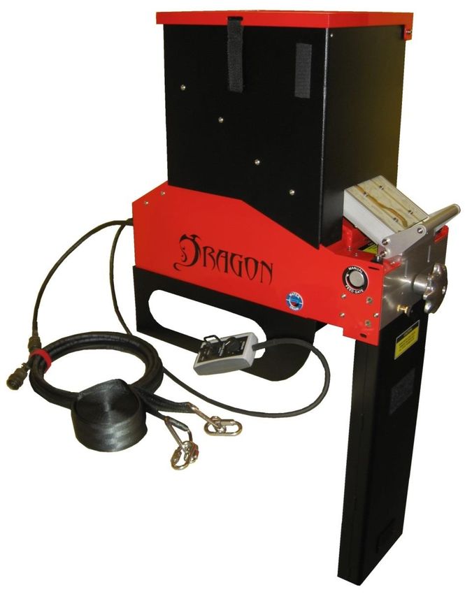
Revision Summary
Version   Release Date                      Revision Description
                         • General Revision
2021A     13-Apr-2021
                         • Appendix A updated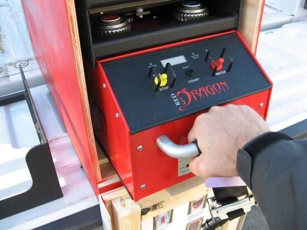
Table of Contents
Section 1: System Overview ........................................................................................ 1
  Red Dragon Dispenser .............................................................................................................................. 2
  Components .............................................................................................................................................. 3
  Optional Components ............................................................................................................................. 10
Section 2: Operations ................................................................................................. 11
  Pilot and Operator Responsibilities......................................................................................................... 11
  Pre-Flight Procedures.............................................................................................................................. 12
  In-Flight Procedures................................................................................................................................ 21
Section 3: Emergency Procedures ............................................................................ 23
  Equipment Malfunctions ......................................................................................................................... 23
  Aircraft Emergency ................................................................................................................................. 25
  Safety Considerations ............................................................................................................................. 26
Section 4: Troubleshooting ........................................................................................ 27
  Hopper Agitator Non-Operational .......................................................................................................... 27
  Shuttle Drive Non-Operational ............................................................................................................... 28
  Feed Gates Won’t Open .......................................................................................................................... 29
  Drop Rate Not Changing ........................................................................................................................ 29
  No Emergency Water .............................................................................................................................. 30
  Dragon Eggs Not Igniting ....................................................................................................................... 30
  Main Circuit Breaker Trips ..................................................................................................................... 30
Section 5: Specifications ............................................................................................ 31
  Dispenser Specifications ......................................................................................................................... 31
  Dragon Egg Specifications ..................................................................................................................... 33
Section 6: Maintenance and Service ......................................................................... 35
  Cleaning and Storage .............................................................................................................................. 35
  Red Dragon Tool Kit .............................................................................................................................. 41
  Spare Parts .............................................................................................................................................. 42
Section 7: Testing ....................................................................................................... 43
  Bench Testing ......................................................................................................................................... 43
  Hangfire Test Procedure ......................................................................................................................... 45
Section 8: Warranty..................................................................................................... 47
Appendix A: Dragon Tracker ...................................................................................... 49

Overview ............................................................................................................................................... 49
  Application Software ......................................................................................................................... 51
Appendix B: Safety Data Sheet .................................................................................. 57
Section 1: System Overview

Section 1: System Overview
The use of controlled burning provides an effective tool in forest and wildland management. Helicopter
deployed aerial ignition devices have a lengthy, proven track record of initiating these burns in an
efficient, safe and controllable manner.

Dragon Eggs
Dragon Eggs are spherical aerial ignition devices. They consist of a
polystyrene plastic shell containing potassium permanganate. In this state,
the spheres are stable provided the shells remain undamaged. When
injected with ethylene glycol, an exothermic reaction initiates. After a
delay of approximately 30 seconds, the sphere ignites. Once ignited, the
plastic shell is consumed as fuel.

The Red Dragon injects a constant volume of glycol into each Dragon Egg regardless of the drop rate set
by the operator. As such, the auto-ignite delay time is influenced primarily by the temperatures of the
Dragon Eggs and glycol. The indicated delay times are based on air/sphere temperatures of 50 –70
degrees F (10 – 20 degrees C). Increased temperatures will decrease the delay time. By diluting the
glycol with water to a 50/50 mix, the delay time can be increased.

                                             WARNING
 The potassium permanganate within the sealed Dragon Egg is classified as a hazardous substance and,
 as such, must be handled and transported in the correct manner. Potassium permanganate (KMnO4) is
 a strong oxidizer and will react violently with certain chemicals including:
             Antimony                        Aluminum Carbide                       Arsenic
          Ethylene Glycol                          Glycerol                   Hydrogen Trisulphide
        Hydrogen Peroxide                        Phosphorus                         Sulphur
          Sulphuric Acid                           Titanium

 Potassium permanganate should not be inhaled or otherwise absorbed or come in contact with the skin.

                                                              Red Dragon Operations Manual              1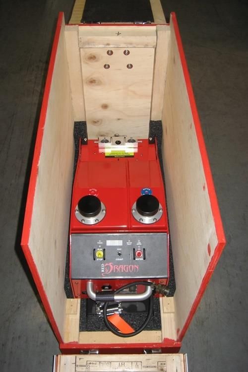
Section 1: System Overview

Red Dragon Dispenser
The Red Dragon Dispenser, developed by SEI Industries Ltd., represents the next generation of aerial
sphere dispensers. The primary function of the Red Dragon dispenser is to inject a measured amount of
ethylene glycol into Dragon Eggs, thereby initiating an exothermic reaction, and then expel the primed
spheres from the aircraft.

Operational Features
   •   Seven drop rates from 25 – 175 spheres per minute.
   •   Tethered remote control to adjust the drop rate and control the feed gates.
   •   Positive displacement glycol pumps ensure constant glycol volume regardless of drop rate.
   •   Smart software minimizes the chance of sphere jams occurring when feed gates open.
   •   Re-settable sphere counter.
   •   Large capacity hopper holds 650 spheres.
   •   Removable base to fit various helicopter configurations.
   •   Tank drain valves.

Safety Features
   •   Automatic jam detection and clearing system.
   •   Manual hand-wheel to clear a jam when no power is available.
   •   Emergency water pump with battery backup power supply.
   •   Low water interlock to prevent start up when the emergency water supply is low.
   •   Manual override to close and lock the feed gates.
   •   Quick release hopper to permit ejection of the hopper and the unused spheres in an emergency.

                                                                Red Dragon Operations Manual           2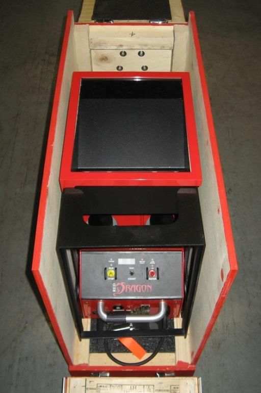
Section 1: System Overview

Components
The Red Dragon dispenser consists of a number of major components:

   •     Hopper – Stores the unprimed spheres.
   •     Feed Gate Assembly – Controls the flow of spheres into the injection head.
   •     Injection Head – Injects the spheres with glycol.
   •     Outlet Chute – Directs the spheres from the injection head to a point below the aircraft.
   •     Tank Assembly – Contains the water and glycol tanks and acts as the frame for the unit.
   •     Control Panel – Houses the control board, control switches and indicators.
   •     Remote Control – Controls the feed gates and drop rate.
   •     Power Cord – Connects dispenser to aircraft’s auxiliary power system.
   •     Base Mounting System – Secures the unit to the aircraft.

    Hopper

    Control Panel

           Tank                                                                          Feed Gate
       Assembly

                                                                                         Injection
                                                                                         Head
    Base

                                                                                         Outlet Chute

       Power Cord
                           Y Strap           Remote Control

                                                                 Red Dragon Operations Manual           3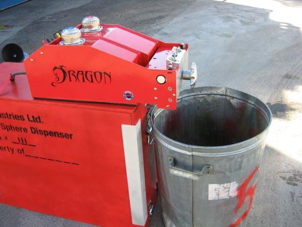
Section 1: System Overview

Mounting System
The standard base supplied with the Red Dragon
allows the unit to be installed into a Bell series 206
helicopter. The base may be removed to allow the
installation into other helicopters featuring a flat cabin
floor.
The Red Dragon is secured into the helicopter using a
“Y” strap that is adjustable to fit a range of cabin
widths.

Tank Assembly
The tank assembly houses the water and glycol tanks.
It also acts as the framework to which the other
components are mounted. The water and glycol
systems have color-coded filler breather caps. The
caps have integral strainers to prevent contamination.
Each tank is also fitted with a drain valve which can be
operated using a slotted screwdriver. A short length of
tubing attaches to either drain valve to direct the fluid
into a suitable container.

Power Cords
The standard power cord is a 15 ft. jacketed cable
fitted with an MS3116F-12-3P plug to connect to the
aircraft’s 28 VDC power supply (Pin A +28VDC, Pin
B GND). The other end of the power cord terminates
in a receptacle. A short pigtail cord from the
machine’s front panel has a mating plug.

                                                             Red Dragon Operations Manual   4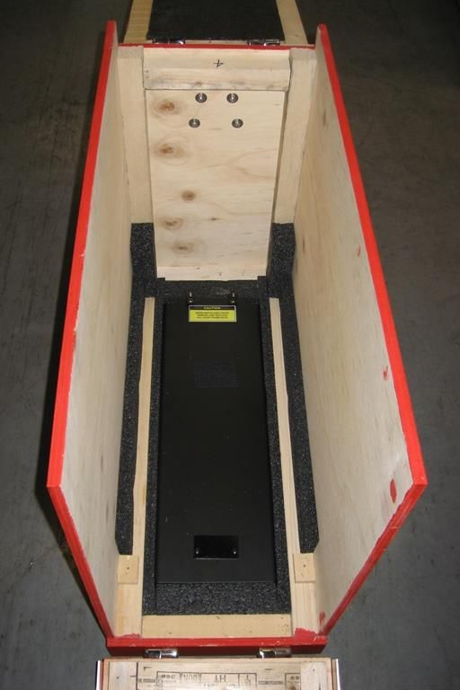
Section 1: System Overview

A bench test power cord is also provided. One
end of the cord is provided with a receptacle to
connect to the pigtail cord on the main control
panel. The other end of the cord is fitted with
1/4” ring terminals for attachment to an
external power supply/battery for bench test
purposes.

Hopper
The hopper provides storage capacity for 650 Dragon
Eggs and can be filled by the operator before or during
operation. An agitator within the hopper provides a
constant supply of spheres to the feed gates via two
chutes.
The chutes have a clear window to allow the operator
to monitor the flow of spheres from the hopper.
Secondary stops, located at the outlet of the chutes,
automatically close and stop the flow of spheres when
the hopper is removed from the dispenser.
The hopper has a hinged lid which may be configured
so that it opens towards or away from the operator. A
clear polycarbonate window allows the operator to
monitor the level of spheres in the hopper.

Power to the hopper is provided through a multi-pin connector that automatically mates when the hopper
is placed onto the feed gate assembly. In an emergency, the hopper can be quickly removed by grasping
the locking handle and lifting upwards.

                                                   NOTICE
 With the lid removed, the Dragon eggs are stable in the hopper under normal flight conditions. The
 operating authority may decide to permanently remove the lid to facilitate filling operations.

                                                             Red Dragon Operations Manual           5
Section 1: System Overview
Feed Gate Assembly
The feed gate assembly controls the flow of spheres from the hopper into the injection head.
Manual Knob. Feed Gates Control Rod
Open solenoid. Close solenoid.
As the spheres exit the hopper, they enter two vertical passages in the feed gate assembly. Each passage
has a feed gate attached to a common control rod. Pushing the rod inwards causes the feed gates to block
the passages and stop the flow of spheres.
In normal operation, the position of the feed control rod and the feed gates is controlled by two solenoids,
under direction, from the main controller.
To close the gates, the close solenoid energizes and pushes the rod inwards. When the rod is fully
inwards, a spring-loaded pin locks into a groove in the rod to prevent it from opening. The close solenoid
then de-energizes.
To open the gates, the open solenoid energizes and pulls out the locking pin. An opening spring on the
feed control rod causes it to move outwards into the fully open position. The open solenoid then de-
energizes.
There is a manual feed gate knob located on the end of the control rod. In an emergency, pushing on the
knob will also close and lock the feed gates. The feed gates cannot be opened manually.
The feed gate assembly is located on top of the injection head by two vertical pins. It is held in place by
two manual locking cams. It can be quickly disconnected from the injection head to allow access for
cleaning.
Red Dragon Operations Manual 6Section 1: System Overview
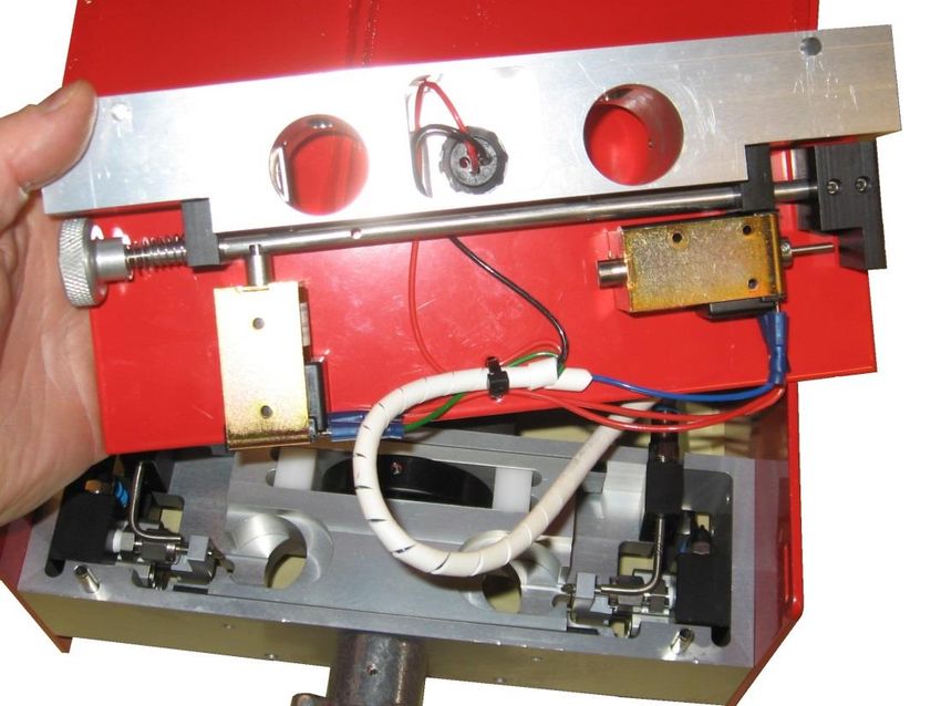
Injection Head
Shuttle Water
drive nozzle.
motor.
Cam.
Injection
shuttle. Glycol
pump.
Hand
wheel.
The injection head is the heart of the Red Dragon Dispenser. It is here that the Dragon Eggs are pierced
by a hollow needle, injected with a controlled amount of glycol and then ejected from the machine.
The injection shuttle is located in the head. The shuttle guides the spheres as they pass through the
injection head. The shuttle is driven in a reciprocating motion by a DC motor and a single offset cam. As
a sphere exits the feed gate assembly, it falls into one of two cavities in the injection shuttle. Outward
motion of the shuttle causes the sphere to contact the injection needle and be punctured. As the shuttle
moves further outward, the sphere presses against the pump arm causing a controlled amount of glycol to
be injected into the sphere.
The shuttle then reverses direction, extracting the sphere from the injection needle. It passes through the
center position and continues to its full inward position. At that position, the cavity is over the exit chute,
and the primed sphere drops from the shuttle and exits the machine. The two shuttle cavities are arranged
such that when one side is injecting a sphere, the other side is dropping a sphere down the exit chute.
This gives a steady output of spheres from the machine.
The constant displacement glycol pumps deliver the
same quantity of glycol on every stroke regardless of Injection Needle
the drop rate. This eliminates the need for the operator
to calibrate the glycol system. When no sphere is
present, the pump arm is not activated and no glycol
flows.
Pump Arm
Red Dragon Operations Manual 7Section 1: System Overview
If the machine is operated until the glycol pumps drain the tank, the pumps will lose their prime. The
pump assemblies may be removed from the injection head and re-primed by squeezing the pump arm
repeatedly until glycol flows from the injection needle. Each pump assembly is secured to the injection
head by two captive screws.
The injection head also includes two water nozzles directed into the injection chambers. These nozzles
are connected to a water pump and reservoir. In an emergency, the water pump can be activated by the
operator to extinguish a fire in the injection chambers.
The machine is equipped with an automatic system to detect and clear sphere jams in the shuttle.
However, should the automatic system fail to clear a jam, or the unit lose electrical power, a handwheel is
fitted to the outboard end of the drive shaft. This handwheel can be used to turn the drive motor and cam
in either direction to clear a jammed or broken sphere.
Control Panel
Power Run / Stop LED Motor Fault Low Water
Indicator Indicator Display Indicator Indicator
Pump
Indicator
Run / Stop Count Reset Water Pump
Switch Switch Switch
The control panel is the brains of the Red Dragon system. A single circuit board mounted beneath the
main control panel contains the microprocessor and all additional components.
The green “POWER” indicator on the main control panel illuminates when the machine is connected to
an external power source. External power to the machine is routed through a 5A, type MS3320 manually
re-settable circuit breaker which is located on the vertical front panel below the main control panel.
Pulling the breaker out cuts all external power to the machine.
The “RUN/STOP” toggle switch controls the operation of the hopper and the shuttle drive motor. When
the switch is set to the “RUN” position, the hopper drive motor starts and the yellow indicator above the
switch illuminates. The shuttle drive motor does NOT start at this time.
Red Dragon Operations Manual 8Section 1: System Overview
Operation of the shuttle drive motor is controlled by the feed gate switch on the tethered remote control.
With the “RUN/STOP” switch in the “RUN” position and the feed gate switch toggled to the “OPEN”
position, the feed gates open, and the shuttle drive motor starts. When the feed gate switch is toggled to
the “CLOSE” position, the feed gates close but the shuttle drive motor continues to run for two more
revolutions to purge the shuttle of any primed spheres. After the purge, the drive motor stops.
The feed gates and shuttle drive motor cannot be activated when the “RUN/STOP” switch is in the
“STOP” position. However, if the switch is moved to the “STOP” position when the feed gate is open
and the shuttle drive motor is already running, the feed gates will close and the motor will purge for three
revolutions and then shut down.
The controller measures the actual speed of the shuttle drive motor and can determine when a jam
condition has occurred in the injection shuttle. When the controller senses that a jam has occurred, the
“MOTOR FAULT” indicator illuminates and the controller adjusts the shuttle drive motor direction and
speed to automatically clear the jam. Once the jam is cleared, the unit returns to normal operation.
The momentary “WATER” toggle switch controls the emergency water pump. When the pump is
activated, the indicator above the switch illuminates. The pump normally receives its power from the
external power supply. However, if the unit loses external power, there is a battery backup that supplies
power to the emergency water pump.
This battery is constantly charging when the unit is connected to an external
power supply. If the unit has been stored for a long period of time and the
battery has lost its charge, the warning message “bAtt” will flash on the LED
segment display. The low battery condition WILL NOT prevent operation of
the Red Dragon.
On older Red Dragon dispensers, with serial numbers from 101-117, there is a battery isolation switch
located on the underside to prevent battery discharge over time.
There is a water level sensor located in the water tank. The “LOW WATER” indicator will illuminate
when there is insufficient water in the tank for the machine to safely operate. The shuttle drive motor
WILL NOT start when the “LOW WATER” indicator is illuminated.
The controller counts the number of spheres that have been processed and
stores the information in two counters. The sphere count for the current
operation is normally displayed on the segment LED display. The count goes
to 9999 and then wraps to 0 and restarts. Pushing and holding the “RESET”
toggle switch for two seconds resets the operation count to zero.
The lifetime count of spheres is displayed on the segment LED by pushing the
“RESET” toggle switch momentarily. The lifetime count equals the number
displayed multiplied by 1000. These counts are maintained in memory even
when the unit is powered down.
The design of the control panel switches and indicators inhibits water ingress onto the circuit board.
However, it does not provide a watertight enclosure and the panel is not intended to be immersed or to be
sprayed with water.
Red Dragon Operations Manual 9Section 1: System Overview
Tethered Remote Control
The tethered remote control is a hand-held device which allows the
operator to control the feed gates, adjust the drop rate, and monitor the
machine operation.
The green “PWR” indicator illuminates when the machine is receiving
power from an external source.
The yellow “RUN” indicator illuminates when the hopper drive motor
is operating. The indicator flashes when the shuttle drive motor is
operating.
The red “FAULT” indicator flashes when the controller detects a jam
occurring in the injection shuttle.
The “FEED GATE” switch is a three position momentary toggle that
allows the operator to open or close the feed gates.
The seven-position “SPEED” control allows the operator to adjust the drop rate while the machine is in
operation. The drop rates correspond to 25-175 spheres per minute in 25 spm increments.
The controller measures the shuttle drive motor speed and uses a PID algorithm to calculate how to adjust
the drive motor power to ensure that the actual drop rate is equal to the selected drop rate.
The tethered remote control is attached to the front panel via a twist lock plug and a 4 ft. jacketed cable.
Optional Components
Power Supply
A 110 VAC portable power supply providing 24VDC x 10A is
available for bench testing the Red Dragon.
This power supply can also be used to charge the backup
battery, if required.
Dragon Tracker
The Dragon Tracker uses a GPS receiver to track and map the
dispensed spheres. See Appendix A for more details.
Red Dragon Operations Manual 10Section 2: Operations
Section 2: Operations
Pilot and Operator Responsibilities
The occupants of the aircraft shall be limited to the pilot, the Red Dragon operator and the firing boss, if
essential to the mission.
Pilot Duties and Responsibilities
The pilot-in-command is responsible for all matters related to aircraft operations and safety, including
installation and operation of the Red Dragon in the helicopter.
The pilot-in-command must be totally familiar with the system and its operation. The pilot shall have
approval for aerial ignition operations and receive a briefing on the operational objectives as well as
ground and flight procedures.
In addition to the familiarization received during the pre-flight test, the pilot must be provided with
specific instructions regarding destination, objective and general procedures.
Any speed or altitude restrictions on the operation of the dispenser should be based on the flight
restrictions of the particular aircraft, the desired accuracy of the ignition spheres, or any other
requirements of the operating authority.
Operator Duties and Responsibilities
The operator is responsible for the preparation, operation, maintenance and care of the Red Dragon
dispenser. The machine operator must have experience with fire behaviour, be mechanically inclined and
have the ability to handle several responsibilities (mental and physical) simultaneously. The operator
must have successfully completed training courses in both dispenser operation and in helicopter safety.
The operator must:
• Determine if the prescribed spacing of ignition is occurring and make any necessary adjustments.
• Determine if any malfunction occurs and act accordingly.
• In the event of a fire within the Red Dragon, determine if the fire has or can be extinguished or if
the unit must be jettisoned.
• Communicate with the pilot on all procedures associated with the burning operation and on any
flight emergencies that may occur during the burn mission.
• Jettison the hopper, if required.
Red Dragon Operations Manual 11Section 2: Operations
Pre-Flight Procedures
Bench Testing
Bench testing shall be performed prior to each burn operation. The purpose of the bench test is to ensure
satisfactory ignition of the Dragon Eggs. The Red Dragon does not require the operator to test and
calibrate the quantity of glycol entering the spheres.
CAUTION
Ignition will occur during this test.
Do not conduct tests in or near areas where combustible sources can be ignited.
An emergency water supply or a fire extinguisher with a minimum 20 BC rating must be available in
close proximity.
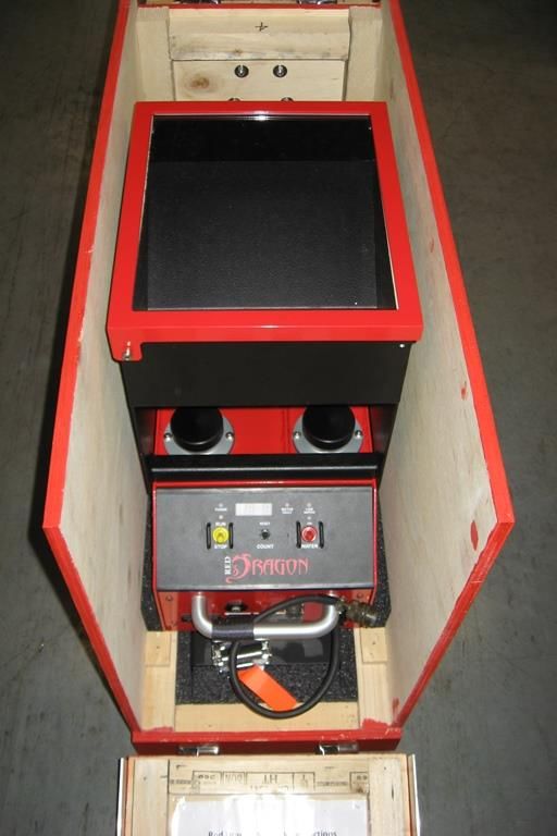
• Remove the base and hopper assembly and set aside.
• Remove the Red Dragon mainframe, close the crate
and place the mainframe on top of the crate.
• Connect the bench test power cord to the Red Dragon
dispenser.
• Connect the other end of the power cord to the
optional 28VDC power supply or to two 12VDC
batteries wired in series to produce 24VDC.
CAUTION
Ensure potassium permanganate does not come into contact with battery acid!
• Ensure glycol and water drain valves are closed
(valve in horizontal position).
Red Dragon Operations Manual 12Section 2: Operations
• Fill the emergency water storage tank. A safety
interlock, indicated by a light on the main body
control panel, will inhibit system operation if the
water tank is not sufficiently filled with water.
• Fill the glycol tank with undiluted and unused
ethylene glycol (anti-freeze).
• Remove the two pump assemblies from the injection
head by loosening the captive screws in the side
panel.
• Prime each pump assembly by squeezing and
releasing the pump arm until glycol squirts from the
injection needle.
Red Dragon Operations Manual 13Section 2: Operations
• Replace the pump assemblies.
• Place an open-top metal container under the injection
head outlet.
• Place two spheres into each of the cavities of the gate
assembly.
CAUTION
Do not put water in metal tray.
• Attach the tethered remote control to the control panel
on the main body.
• Press the main circuit breaker on the front panel to the
reset position.
• The “POWER” indicator on the main control
panel will illuminate.
• Switch the “RUN/STOP” switch on the main control
panel to “RUN”.
Red Dragon Operations Manual 14Section 2: Operations
• Set the “SPEED” switch on the tethered remote
control to “1.”
• Press and release the “FEED GATE” switch on the tethered remote control to the “OPEN”
position.
• The feed gates will open.
• The shuttle drive motor will start.
• The spheres will be injected and fall out of the injection head outlet.
• When the second sphere exits the machine, begin timing the ignition delay.
• The injected spheres should ignite within 25-30 seconds depending on temperature. Only
three of the four spheres will ignite as the first sphere is not injected.
• Press the “FEED GATE” switch on the tethered remote control to “CLOSE.”
• Switch the “RUN/STOP” switch on the main control panel to “STOP.”
NOTICE
Increasing ambient temperatures will decrease the ignition delay time.
Dispenser Installation
CAUTION
The Red Dragon dispenser must be readied for installation outside the safety circle of the helicopter.
• Remove the Red Dragon system from its shipping
container.
Red Dragon Operations Manual 15Section 2: Operations
• Remove the hopper from the machine by grasping the
hopper lock handle and pulling up.
• Ensure the glycol and water drain valves are closed.
• Check/fill the water storage tank. Secure the
filler/breather cap.
• Check/fill the glycol tank with undiluted and unused
ethylene glycol (anti-freeze). Secure the filler/breather
cap.
Red Dragon Operations Manual 16Section 2: Operations
• Remove the right rear door of helicopter.
• Remove all carpet and porous floor coverings.
• Clear the cabin of all loose articles.
• Use duct tape or other means to protect the paint
finish around the door. Consult with the pilot before
using.
• If the support base is required, position appropriately
within the aircraft. If not required, store the base in
the shipping container.
• Install the Red Dragon dispenser in the door opening
of the aircraft so that the injection head protrudes past
the door sill.
• Attach and secure the outlet chute, using a thumbnut
and locking thumbnut on each screw. The gold nut
must be located on the outside of the injection head,
followed by the black nut.
• Attach the Y strap by snapping the “Y” end to the
holes on each side of the outboard end of the
dispenser. Ensure that the strap goes inboard of the
exit chute.
Red Dragon Operations Manual 17Section 2: Operations
• Push the dispenser inboard until the main body fits
snugly into the support base.
• Pass the free end of the strap beneath the belly of the
aircraft and in under the opposite door. Check that
the strap is not twisted or obstructing any aircraft
vents, antennae or release cables. Feed the free end
up and over the roller on the quick release fitting
attached to the other end of the dispenser. Pull the free
end to tighten the strap.
• Replace the hopper assembly onto the dispenser. Slide
the dispenser as far forward as possible to provide
leg-room between the dispenser and the rear seat.
Ensure that the hopper lid opens freely. Tighten the
belly strap snugly.
• Attach the tethered remote control cable to the control
panel receptacle on the main body.
• Check that the main breaker is in the tripped (out)
position.
• Connect the power cable to the auxiliary power outlet
in the helicopter. Connect the other end of the power
cable to the connection on the Red Dragon dispenser.
• Reset the main circuit breaker by pushing it in. The
“POWER” indicator on the main control panel should
illuminate. If the breaker trips immediately, this
indicates that the power supply needs to have its
polarity reversed.
Red Dragon Operations Manual 18Section 2: Operations
Pre-Flight Check
The pre-flight check should be performed daily, prior to intended use. The purpose of this check is to
confirm the readiness of the dispenser and support equipment.
• Press the main circuit breaker on the front panel to the reset position.
• The “POWER” indicator on the main control panel should illuminate.
• The “PWR” indicator on the tethered remote control should illuminate.
• The “LOW WATER” indicator on the main control panel should not illuminate
• Switch the “RUN/STOP” switch on the main control panel to “RUN”.
• The hopper agitator motor should start.
• The indicator above the switch on the main control panel should illuminate.
• The “RUN” indicator on the tethered remote control should illuminate.
• Press the “FEED GATE” switch on the tethered remote control to the “OPEN” position. Switch
activates immediately and does not need to be held.
• The feed gates should open and the shuttle drive motor should start.
• The “RUN” indicator on the tethered remote control should flash.
• The LED display on the main control panel should start counting spheres.
• Adjust the “SPEED” control on the tethered remote control from "1" to "7."
• The shuttle drive motor should speed up.
• Press the “FEED GATE” switch on the tethered remote control to the “CLOSE” position. Switch
activates immediately and does not need to be held.
• The feed gates should close and the shuttle drive motor should run for a few seconds and then
stop.
• Once the shuttle drive motor has stopped, the “RUN” indicator on the tethered remote control
should stop flashing and display a steady yellow light.
• The LED display on the main control panel should stop counting spheres.
• Press the “COUNT” switch on the main control panel to the “RESET” position. HOLD the
switch for a minimum of two seconds.
• The sphere count on the LED display should reset to zero.
• Switch the “RUN/STOP” switch on the main control panel to “STOP.”
• The indicator above the switch on the main control panel should extinguish.
• The hopper agitator motor should stop.
• Press and hold the “WATER” switch on the main control panel to the “ON” position.
• The water pump should start and inject water into both injection chambers.
Red Dragon Operations Manual 19Section 2: Operations
• The indicator above the switch on the main control panel should illuminate.
• Fill the hopper with Dragon Eggs. Close and secure the lid.
• Check that any additional Dragon Eggs carried within the cabin area are properly contained and
secured.
• Check the system for leaks.
• Check that additional one gallon container of water is available.
• Check that a sharp knife is within reach of the operator.
• Check intercom and ground to air communications.
CAUTION
Extra ethylene glycol (antifreeze) shall not be carried in the same compartment as Dragon Eggs. Lead
acid batteries shall not be carried in the cabin to power the Red Dragon.
Red Dragon Operations Manual 20Section 2: Operations
In-Flight Procedures
Dry Run Procedure
• Pilot should make a dry run over the burn area to ensure communications between all parties
involved and to determine boundaries of the burn area.
• After the dry run over the planned area, the pilot and operator should determine the firing pattern
as instructed by the burn boss or fire boss.
• The fire boss should consult the following chart to determine the drop rate for varying spacing
and aircraft speeds.
Dragon Egg Ground Spacing
Aircraft Ground Speed (mph)
10 15 20 25 30 35 40 45 50 55 60 65 70 75
1 35 ft 53 ft 70 ft 88 ft 106 ft 123 ft 141 ft 158 ft 176 ft 194 ft 211 ft 229 ft 246 ft 264 ft
2 18 ft 26 ft 35 ft 44 ft 53 ft 62 ft 70 ft 79 ft 88 ft 97 ft 106 ft 114 ft 123 ft 132 ft
Selected Drop Rate
3 12 ft 18 ft 23 ft 29 ft 35 ft 41 ft 47 ft 53 ft 59 ft 65 ft 70 ft 76 ft 82 ft 88 ft
4 9 ft 13 ft 18 ft 22 ft 26 ft 31 ft 35 ft 40 ft 44 ft 48 ft 53 ft 57 ft 62 ft 66 ft
5 7 ft 11 ft 14 ft 18 ft 21 ft 25 ft 28 ft 32 ft 35 ft 39 ft 42 ft 46 ft 49 ft 53 ft
6 6 ft 9 ft 12 ft 15 ft 18 ft 21 ft 23 ft 26 ft 29 ft 32 ft 35 ft 38 ft 41 ft 44 ft
7 5 ft 8 ft 10 ft 13 ft 15 ft 18 ft 20 ft 23 ft 25 ft 28 ft 30 ft 33 ft 35 ft 38 ft
Red Dragon Operations Manual 21Section 2: Operations
Dispensing Dragon Eggs
• Set the "RUN/STOP" toggle on the main control panel to "RUN." The system status lights
should illuminate and the hopper motor should activate.
• Set the "SPEED" switch on the tethered remote control to the desired setting.
• Enter the first flight line at operational speed and set the feed gate toggle on the tethered remote
control to "OPEN." The drive motor should activate.
• Ensure a steady progression of spheres exiting the hopper.
• The feed rate can be adjusted at any time during the operation.
• As required, the feed gate toggle can be set to either "OPEN" or “CLOSE” to start or stop the
flow of spheres through the machine.
• When the feed gate toggle is set to “CLOSE,” the spheres already within the injection head will
continue to be primed and ejected until the head is clear of all spheres at which time the drive
motor will stop.
• Follow the procedures for an emergency situation as described in section 3 Emergency
Procedures.
Dispenser Shut-Down
• Do not exit the burn area until all operations have ceased.
• Ensure that the feed gates are closed.
• Toggle the "RUN/STOP" switch to "STOP."
• Ensure that no spheres remain in the injection head.
• The aircraft may then leave burn area.
• Clean the unit according to daily maintenance directions in section 6 Maintenance and Service.
System Fault Status
For troubleshooting information, see section 4 Troubleshooting. Emergency repairs or system clean-out
can be done by the operator at a convenient landing spot, using the troubleshooting guide, if the required
tools/spare parts are available.
Red Dragon Operations Manual 22Section 3: Emergency Procedures
Section 3: Emergency Procedures
Equipment Malfunctions
The Red Dragon dispenser has been designed to maximize safety under normal operating conditions. By
following the correct procedures, as outlined within this manual, the system will provide a consistent
supply of Dragon Eggs to the target within minimal interruption. However, equipment malfunctions can
still occur and, due to the nature of the operation, safety must remain paramount. Interruption of
operation caused by a jammed sphere or a power failure will result in a primed sphere remaining within
the injection head. Spheres remaining within the head may be primed with glycol and will auto-ignite
within the head.
Jammed Sphere
The operator is alerted to a jammed sphere by any of the following conditions:
• “FAULT” indicator on the tethered remote control flashes.
• “MOTOR FAULT” indicator on the main control panel illuminates.
• Manual hand-wheel stops rotation when the feed gates are open and machine has power.
• Flow of spheres into the gate block stops when the feed gates are open and machine has power.
If a sphere jam occurs in the machine, take the following immediate actions:
• If automatic clearing fails, notify the pilot of the situation.
• Press the manual feed control knob to close and lock the feed gates.
• Rotate the manual hand wheel in the reverse and forward directions to clear the jam.
• If jam clears, notify the pilot that burning can recommence.
• Toggle the feed gate switch to the “OPEN” position to reopen feed gates.
CAUTION
If the hopper is removed during operations, the top two spheres in the gate assembly must be retrieved
before re-attaching the hopper. Failure to do so may prevent opening of the gates.
If jam cannot be cleared and sphere ignition occurs:
• Toggle the water switch to the “ON” position and hold until the combustion has stopped.
• If necessary, pour the additional container of water into the hopper.
• Clean the ignition head as detailed in section 6 Maintenance and Cleaning.
WARNING
If a fire continues or re-ignites, land immediately.
Red Dragon Operations Manual 23Section 3: Emergency Procedures
Power Failure
Power failure to the Red Dragon machine can be caused by the following conditions:
• Tripping of the main circuit breaker.
• Accidental disconnection of the power cord.
• Tripping of the aircraft circuit breaker.
• General aircraft power system failure.
The operator is alerted to a power failure by any of the following conditions:
• All indicators on the tethered remote control and main control panel are extinguished.
• Manual hand-wheel stops rotating when the feed gates are open.
• Flow of spheres into the gate block stops when the feed gates are open.
If a power failure occurs, take the following immediate actions:
• Notify the pilot of the situation.
• Press the manual feed control knob to close and lock the feed gates.
• Rotate the manual hand-wheel three full turns to clear any remaining spheres in the ignition head.
• Investigate the cause of the power failure.
Red Dragon Operations Manual 24Section 3: Emergency Procedures
Aircraft Emergency
In the event of an aircraft emergency, the pilot may direct the operator to jettison all or part of the Red
Dragon dispenser to remove the primary fuel and oxidizer sources from the aircraft.
CAUTION
Request permission from the pilot before jettisoning any equipment. Look for a suitable location to
jettison, making every attempt to avoid dropping equipment over a developed area.
Hopper Jettison
To jettison the hopper, take the following immediate actions:
• Receive direction from pilot to jettison the hopper.
• Close and secure the hopper lid.
• Grasp the hopper and lift clear of the dispenser.
• Jettison the hopper through the door opening making sure to clear the aircraft structure.
Machine Jettison
If absolutely required, the remaining pieces of the Red Dragon can also be jettisoned from the aircraft.
To jettison the machine, take the following immediate actions:
• Receive direction from pilot to jettison the machine.
• Grasp the power cord on each side of the connection, twist and pull apart.
• Cut the Y strap with the cutter provided.
• Lift the main body of the machine clear of the support base and jettison through the door opening
making sure to clear the aircraft structure.
• Jettison the support base through the door opening making sure to clear the aircraft structure.
• Jettison any remaining Dragon Eggs and debris.
Red Dragon Operations Manual 25Section 3: Emergency Procedures
Safety Considerations
Dragon Eggs
Although stable, prior to priming with ethylene glycol, the material within the sealed Dragon Egg is
classified as a hazardous substance and, as such, must be handled and transported in the correct manner.
Potassium permanganate (KMnO4) is a strong oxidizer and will react violently with certain chemicals as
indicated in the following table.
WARNING
The potassium permanganate within the sealed Dragon Egg is classified as a hazardous substance and,
as such, must be handled and transported in the correct manner. Potassium permanganate (KMnO4) is
a strong oxidizer and will react violently with certain chemicals including:
Antimony Aluminum Carbide Arsenic
Ethylene Glycol Glycerol Hydrogen Trisulphide
Hydrogen Peroxide Phosphorus Sulphur
Sulphuric Acid Titanium
Potassium permanganate should not be inhaled or otherwise absorbed or come in contact with the skin.
A full MSDS sheet for the chemical is included in the appendix.
Red Dragon Operations Manual 26Section 4: Troubleshooting
Section 4: Troubleshooting
This section describes remedial actions to problems that are encountered during the pre-flight bench
testing and pre-flight check (see section 2 Operations, Pre-Flight Procedures). The actions are limited to
those which can be performed in the field by an operator with limited tools. For more advanced trouble-
shooting, consult the Red Dragon Service manual.
Problems occurring during flight are covered in section 3 Emergency Procedures, Equipment
Malfunctions.
Hopper Agitator Non-Operational
Check that the aircraft’s auxiliary circuit breaker is not
tripped.
Check that the power cord is properly attached to the aircraft
“POWER” indicator auxiliary outlet.
No Power
not illuminated Check that the power cord is properly attached to the pigtail
cable of the dispenser.
Check that the dispenser’s main circuit breaker is not
tripped.
“LOW WATER” Check water level in tank. Add water as required.
Low Water
indicator
Interlock Check water drain valve is closed.
illuminated
“RUN” indicator not
Switch Setting Check that the “RUN / STOP” switch is in “RUN” position.
illuminated
Hopper “”RUN” indicator
Check that the hopper is seated correctly on gate assembly.
Connection illuminated
Toggle the :RUN / STOP” switch to the “STOP” position and
wait for the hand wheel to stop rotating.
Agitator “RUN” indicator Remove the hopper from the gate assembly.
Linkage illuminated Check that the hopper agitator mechanism is not jammed.
Check that the hopper agitator linkages are correctly
attached.
Red Dragon Operations Manual 27Section 4: Troubleshooting
Shuttle Drive Non-Operational
Check that the aircraft’s auxiliary circuit breaker is not tripped.
Check that the power cord is properly attached to the aircraft
“POWER” indicator auxiliary outlet.
No Power
not illuminated Check that the power cord is properly attached to the pigtail
cable of the dispenser.
Check that the dispenser’s main circuit breaker is not tripped.
“LOW WATER” Check water level in tank. Add water as required.
Low Water
indicator
Interlock Check water drain valve is closed.
illuminated
“RUN” indicator not
Switch Setting Check that the “RUN / STOP” switch is in “RUN” position.
illuminated
Wait for two seconds after “RUN / STOP” has been switched
“RUN” indicator to the “RUN” position.
System Delay
steady illumination
Toggle the “FEED GATE” switch to the “OPEN” position.
Check that the tethered remote control is properly plugged into
Tether “RUN” indicator the receptacle on the front panel.
Connection steady illumination
Toggle the “FEED GATE” switch to the “OPEN” position.
Switch the “RUN / STOP” switch to the “STOP” position.
Pull the main circuit breaker.
Remove the hopper.
“MOTOR FAULT” Unlock the gate assembly and remove.
Jammed Sphere indicator
Examine shuttle cavities and remove jammed and/or broken
illuminated
spheres. Rotate manual hand wheel as requied. Blow out with
compressed air if available.
Replace gate assembly and hopper.
Reset the main circuit breaker.
Red Dragon Operations Manual 28Section 4: Troubleshooting
Feed Gates Won’t Open
Check that the aircraft’s auxiliary circuit breaker is not
tripped.
Check that the power cord is properly attached to the aircraft
“POWER” indicator auxiliary outlet.
No Power
not illuminated Check that the power cord is properly attached to the pigtail
cable of the dispenser.
Check that the dispenser’s main circuit breaker is not
tripped.
“LOW WATER” Check water level in tank. Add water as required.
Low Water
indicator
Interlock Check water drain valve is closed.
illuminated
“RUN” indicator not
Switch Setting Check that the “RUN / STOP” switch is in “RUN” position.
illuminated
Wait for two seconds after “RUN / STOP” has been switched
“RUN” indicator to the “RUN” position.
System Delay
steady illumination
Toggle the “FEED GATE” switch to the “OPEN” position.
Check that the tethered remote control is properly plugged
Tether “RUN” indicator into the receptacle on the front panel.
Connection steady illumination
Toggle the “FEED GATE” switch to the “OPEN” position.
Switch the “RUN / STOP” switch to the “STOP” position and
wait for the hand wheel to stop rotating.
Remove the hopper.
Unlock the gate assembly and remove.
Check the sphere path in the gate assembly for obstructions
Jammed Feed “RUN” indicator
preventing the gates from opening.
Gates flashing
Switch the “RUN / STOP” switch to the “RUN” position and
wait until the shuttle drive motor starts.
Toggle the “FEED GATE” switch between the “OPEN” and
“CLOSE” positions and check for movement of the feed
gates
Drop Rate Not Changing
Remote Check that the remote control is properly plugged into the
Connection receptacle on the front panel.
Red Dragon Operations Manual 29Section 4: Troubleshooting
No Emergency Water
Water Tank “LOW WATER” Check water level in tank. Add water as required.
Empty indicator illuminated Check water drain valve is closed.
Check that the aircraft’s auxiliary circuit breaker is not
tripped.
Check that the power cord is properly attached to the aircraft
“POWER” indicator auxiliary outlet.
No Power
not illuminated Check that the power cord is properly attached to the pigtail
cable of the dispenser.
Check that the dispenser’s main circuit breaker is not
tripped.
Battery “bAtt” indicated on
Recharge backup battery.
Discharged LED display
Dragon Eggs Not Igniting
Check glycol level in tank. Add glycol as required.
Check glycol drain valve is closed.
Glycol Tank
Empty Remove pump assemblies from injection head.
Depress and release pump arms repeatedly until glycol flows
from injection needles.
Remove pump assemblies from injection head.
Air in Glycol
System Depress and release pump arms repeatedly until glycol flows
from injection needles.
Remove pump assemblies from injection head.
Plugged
Needle Check that injection needles are not plugged. Clean as
required.
Main Circuit Breaker Trips
Reverse
Check the polarity of the power supply.
Polarity
Red Dragon Operations Manual 30Section 5: Specifications
Section 5: Specifications
Dispenser Specifications
Performance
Number of speeds 7
Min. drop rate 25 spheres per min.
Max. drop rate 175 spheres per min.
Hopper capacity 650 spheres
Power
Voltage 24-32 VDC
Connector MS3116F-12-3P (Pin A +28V, Pin B GND)
Main circuit breaker 5A, MS3320, manual reset
Operational Weight
Red Dragon dispenser, tanks empty 48.0 lbs 21.8 kg
Ethylene glycol 7.9 lbs 3.6 kg
Water supply for emergency use 4.1 lbs 1.9 kg
Dragon Eggs – (650 spheres) 6.8 lbs 3.1 kg
Total operational weight 66.8 lbs 30.4 kg
Red Dragon Operations Manual 31Section 5: Specifications
Dispenser Dimensions
Length 24.50 in 62.4 cm
Width 10.75 in 27.3 cm
Height
With support base 24.00 in 61.0 cm
Without support base 19.00 in 48.3 cm
Fluid Volumes
Glycol tank 0.8 US gal 3.2 liter
(A full glycol tank will inject approximately 5,000 Dragon Egg spheres.)
Water tank
Full 0.5 US gal 1.9 liter
Minimum required 0.2 US gal 0.8 liter
Shipping Crate Dimensions
Length 31 in 79 cm
Width 13 in 33 cm
Height 24 in 61 cm
Shipping Weight
Red Dragon dispenser, tanks empty 48 lbs 22 kg
Shipping container 44 lbs 20 kg
Miscellaneous 2 lbs 1 kg
Total shipping weight 94 lbs 43 kg
Red Dragon Operations Manual 32Section 5: Specifications
Dragon Egg Specifications
Weights
Individual Dragon Egg 0.17 oz 4.8 g
Box of 1,000 Dragon Eggs
Potassium permanganate (KMnO4) 6.6 lbs 3.0 kg
High-impact polystyrene (HIPS) shells 4.0 lbs 1.8 kg
Packaging material 1.5 lbs 0.7 kg
Gross weight 12.1 lbs 5.5 kg
Dimensions
Individual Dragon Egg 1.0 in 26.0 mm
Box of 1,000 Dragon Eggs
Length 16.0 in 40.6 cm
Width 9.0 in 22.9 cm
Height 10.3 in 26.1 cm
Ignition Parameters
Injection to the first combustion (smoke) 25 seconds @ 55o F (13o C)
Injection to full combustion (flame) 35 seconds @ 55o F (13o C)
Total useful combustion time 80 seconds @ 55o F (13o C)
NOTICE
Increasing ambient temperatures will decrease the ignition delay time.
Red Dragon Operations Manual 33Section 5: Specifications
Safety
Although stable, prior to priming with ethylene glycol, the material within the sealed Dragon Egg is
classified as a hazardous substance and, as such, must be handled and transported in the correct manner.
Potassium permanganate (KMnO4) is a strong oxidizer and will react violently with certain chemicals as
indicated below. In addition, potassium permanganate should not be inhaled or otherwise absorbed or
come in contact with the skin.
WARNING
The potassium permanganate within the sealed Dragon Egg is classified as a hazardous substance and,
as such, must be handled and transported in the correct manner. Potassium permanganate (KMnO4) is
a strong oxidizer and will react violently with certain chemicals including:
Antimony Aluminum Carbide Arsenic
Ethylene Glycol Glycerol Hydrogen Trisulphide
Hydrogen Peroxide Phosphorus Sulphur
Sulphuric Acid Titanium
Potassium permanganate should not be inhaled or otherwise absorbed or come in contact with the skin.
A full MSDS sheet for the chemical is included in the appendix.
Dragon Egg Shipping Box Certifications
• The complete package has been tested to meet the requirements of ISTA procedure 1A.
• The complete package has been tested to meet the requirements of UN 4G combination
packaging.
Red Dragon Operations Manual 34Section 6: Maintenance and Service
Section 6: Maintenance and Service
Cleaning and Storage
This section provides an overview of service and maintenance that can be performed in the field. The
accompanying service manual provides a more extensive review.
Cleaning
This cleaning procedure shall be performed immediately following burn operations. Delay in cleaning
the unit will result in the hardening of any remaining chemical in the injection head.
• Remove the Red Dragon dispenser from the aircraft.
• Wipe down the aircraft floor.
• Remove any protective tape that was installed on the aircraft door sill or fuselage.
• Remove the hopper.
• Empty any remaining Dragon Eggs into an
appropriate container.
• Wipe down the inner surfaces of the hopper to
remove any potassium permanganate dust.
• Check the agitator and linkages for signs of
excessive wear.
• Drain the glycol tank.
• Insert 8 mm drain tubing into the glycol drain
valve and place the other end into a suitable
container.
• Open drain valve by rotating with a slotted
screwdriver so that the slot is vertical.
• After draining, close the drain valve and remove
tubing.
Red Dragon Operations Manual 35Section 6: Maintenance and Service
• Drain the water tank.
• Insert 8 mm drain tubing into the water drain
valve and place the other end into a suitable
container.
• Open drain valve by rotating with a slotted
screwdriver so that the slot is vertical.
• After draining, close the drain valve and remove
tubing.
• Remove the feed gate assembly.
• Unlock the feed gate control rod by lifting up on the
open solenoid plunger with a slotted screwdriver. The
feed gate control rod should spring open.
• Clean the sphere paths in the gate assembly using a
cloth and a citrus-based cleaner/degreaser such as
Simple Green all purpose cleaner.
Red Dragon Operations Manual 36Section 6: Maintenance and Service
• Remove the glycol pump assemblies by loosening
captive screws.
• Clean needle bore with the tool provided.
• Clean outside of needle with Scotch-Brite pad
provided.
• Check the sharpness of the needle. If required,
sharpen with the small file provided.
• Check pump operation by squeezing the pump arm
and ensuring a squirt of glycol from the injection
needle.
• Clean the injection shuttle and injection block.
CAUTION
When mixed with water, potassium permanganate will form a dark purple liquid that will cause
staining to metals and skin.
Wear latex gloves and eye protection when cleaning the unit with water.
• Loosen any potassium permanganate and polystyrene
plastic residue from the shuttle and injection block
using the wire brush provided. If available, used
compressed air to blow out the residue.
Red Dragon Operations Manual 37Section 6: Maintenance and Service
• Clean the injection head and shuttle using a cloth and
a citrus-based cleaner/degreaser such as Simple Green
all purpose cleaner. If an appropriate cleaner is not
available, water can be used (with caution).
• Rotate the hand wheel to check the drive system for
smooth operation.
• Check the shuttle guides for excessive wear.
• Check the cam guides in the injection shuttle for
excessive wear.
NOTICE
Do not lubricate the contact points between the injection shell, drive cam and injection block. These
contact surfaces have an aluminium/polyacetal interface which is self-lubricating. The use of products
such as Tri-Flo, WD-40 or light machine oil will cause dirt and permanganate residue to accumulate
and may cause mechanical seizure.
• Replace the pump assemblies.
• Replace the feed gate assembly.
• Wipe down the remaining accessible surfaces on the machine.
Red Dragon Operations Manual 38You can also read