PD7170 Home Theater Projector - Installation & Operation Manual www.planarhometheater.com
←
→
Page content transcription
If your browser does not render page correctly, please read the page content below
PD7170
Home Theater
Projector

 Installation & Operation Manual
  www.planarhometheater.com

TWO YEAR LIMITED WARRANTY
                             For Projectors, Video Processors and Controllers
Congratulations on your purchase of a Planar video product and welcome to the Planar family! With proper
installation, setup and care, you should enjoy many years of unparalleled video performance.
This is a LIMITED WARRANTY as defined in the Magnuson-Moss Warranty Act. Please read it carefully and retain it
with your other important documents.

WHAT IS COVERED UNDER THE TERMS OF THIS LIMITED WARRANTY:

SERVICE LABOR: Planar will pay for service labor by a Planar Authorized Service Center when needed as a result
of manufacturing defect for a period of two (2) years from the effective date of delivery to the end user
(excluding the lamp).

                                                 RY
PARTS (not including the lamp): Planar will provide new or rebuilt replacement parts for the parts that fail due to
defects in materials or workmanship for a period of two (2) years from the effective date of delivery to the end
user. Such replacement parts are then subsequently warranted for the remaining portion (if any) of the original
warranty period.                                A
PROJECTOR LAMP: Planar will pay for service labor by a Planar Authorized Service Center when needed as a
result of a manufacturing defect for a period of six (6) months or 1000 hours, whichever comes first, from the
                                          IN
effective date of delivery to the end user. In addition, Planar will provide a new or rebuilt replacement lamp for
the lamp that fails due to defects in materials or workmanship for a period of six (6) months or 1000 hours,
whichever comes first, from the effective date of delivery to the end user. Such replacement lamps are then
                  IM

subsequently warranted for the remaining portion (if any) of the original warranty period.
               EL

WHAT IS NOT COVERED UNDER THE TERMS OF THIS LIMITED WARRANTY:

This Limited Warranty only covers failure due to defects in materials and workmanship that occur during normal
use and does not cover normal maintenance. This Limited Warranty does not cover cabinets or any
             PR

appearance items; failure resulting from accident, misuse, abuse, neglect, mishandling, misapplication, faulty or
improper installation or setup adjustments; improper maintenance, alteration, improper use of any input signal;
damage due to lightning or power line surges, spikes and brownouts; damage that occurs during shipping or
transit; or damage that is attributed to acts of God. In the case of remote control units, damage resulting from
leaking, old, damaged or improper batteries is also excluded from coverage under this Limited Warranty.
CAUTION: THIS LIMITED WARRANTY ONLY COVERS PLANAR PRODUCTS PURCHASED FROM PLANAR AUTHORIZED
DEALERS. ALL OTHER PRODUCTS ARE SPECIFICALLY EXCLUDED FROM COVERAGE UNDER THIS WARRANTY.
MOREOVER, DAMAGE RESULTING DIRECTLY OR INDIRECTLY FROM IMPROPER INSTALLATION OR SETUP IS
SPECIFICALLY EXCLUDED FROM COVERAGE UNDER THIS LIMITED WARRANTY. IT IS IMPERATIVE THAT INSTALLATION
AND SETUP WORK BE PERFORMED ONLY BY AN AUTHORIZED PLANAR DEALER TO PROTECT YOUR RIGHTS UNDER
THIS WARRANTY. THIS WILL ALSO ENSURE THAT YOU ENJOY THE FINE PERFORMANCE OF WHICH YOUR PLANAR
PRODUCT IS CAPABLE WHEN INSTALLED AND CALIBRATED BY PLANAR AUTHORIZED PERSONNEL.

Planar PD7170 Installation/Operation Manual              iii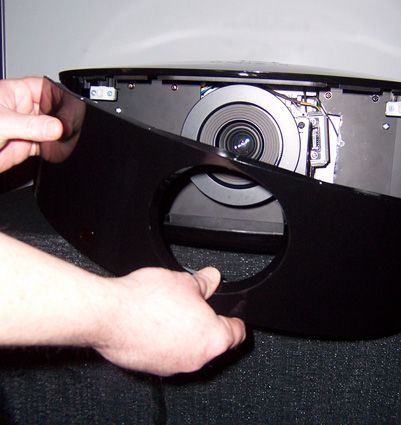
RIGHTS, LIMITS AND EXCLUSIONS:

Planar limits its obligations under any implied warranties under state laws to a period not to exceed the warranty
period. There are no express warranties. Planar also excludes any obligation on its part for incidental or
consequential damages related to the failure of this product to function properly. Some states do not allow
limitations on how long an implied warranty lasts, and some states do not allow the exclusion or limitation of
incidental or consequential damages. So the above limitations or exclusions may not apply to you. This warranty
gives you specific legal rights, and you may also have other rights that vary from state to state.

EFFECTIVE WARRANTY DATE:

This warranty begins on the effective date of delivery to the end user. For your convenience, keep the original
bill of sale as evidence of the purchase date.

                                                   RY
IMPORTANT – WARRANTY REGISTRATION:

Please fill out and mail your warranty registration card. It is imperative that Planar knows how to reach you
                                                  A
promptly if we should discover a safety problem or product update for which you must be notified.
                                         IN
CONTACT A PLANAR AUTHORIZED SERVICE CENTER TO OBTAIN SERVICE:

Repairs made under the terms of this Limited Warranty covering your Planar video product will be performed at
                  IM

the location of the product, during usual working hours, providing location of product is within normal operating
distance from a Planar Authorized Service Center. In some instances it may be necessary for the product to be
returned to the Planar factory for repairs. If, solely in Planar’s judgment, location of product to be repaired is
beyond normal operating distance of the closest Planar Authorized Service Center, or the repair requires the unit
               EL

be returned to the Planar factory, it is the owner’s responsibility to arrange for shipment of the product for repair.
These arrangements must be made through the selling Planar Dealer. If this is not possible, contact Planar
directly for a Return Authorization number and shipping instructions. Planar will return product transportation
             PR

prepaid in the United States, unless no product defect is discovered. In that instance, shipping costs will be the
responsibility of the owner.

COPYRIGHT AND TRADEMARKS:

© Copyright 2008 Planar Systems, Inc. This document contains proprietary information protected by copyright,
trademark and other intellectual property laws. All rights are reserved. No part of this manual may be
reproduced by any mechanical, electronic or other means, in any form, without prior written permission of the
manufacturer.
Trademarks and registered trademarks used in this document are the property of their respective owners.

                                                          iv               Planar PD7170 Installation/Operation Manual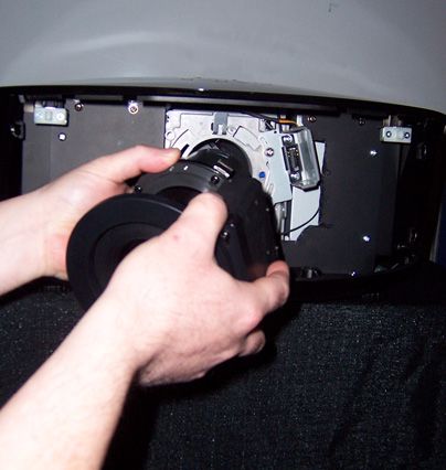
ADDITIONAL INFORMATION:

To locate the name and address of the nearest Planar Authorized Service Center, or for additional information
about this Limited Warranty, please call or write:

                                          Planar Systems, Inc.
                                        1195 NW Compton Drive
                                       Beaverton, OR 97006-1992
                                           Ph: (503) 748-5799
                                          Fax: (503) 682-9441
                                        Toll Free: (866) PLANAR1

                                                RY
                           PLANAR VIDEO PRODUCT INFORMATION
                                               A
                        RETAIN THIS INFORMATION FOR YOUR RECORDS
                                          IN
____________________________________________                        ___________________________________________
Model Purchased                                                     Date
                  IM

____________________________________________________________________________________________________________
Serial Number
               EL

____________________________________________________________________________________________________________
Planar Authorized Dealer Name
             PR

____________________________________________________________________________________________________________
Address
____________________________________________       __________________              ___________________________
City                                               State/Province                 Postal Code
____________________________________________       _________________________________________________________
Phone                                              Fax

Planar PD7170 Installation/Operation Manual           v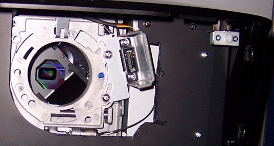
Important Safety Instructions
Thank you for your purchase of this quality Planar product! For best performance, please read this manual
carefully as it is your guide through the menus and operation.

                                           WARNING
              CAUTION                      This symbol is intended to alert the user to the presence of uninsulated
            RISK OF ELECTRIC SHOCK
                  DO NOT OPEN              “dangerous voltage” within the product’s enclosure that may be of
                                           sufficient magnitude to constitute a risk of electric shock.
               CAUTION:
 TO REDUCE THE RISK OF ELECTRIC SHOCK
    DO NOT REMOVE COVER (OR BACK)
                                           This symbol is intended to alert the user to the presence of important
   NO USER SERVICEABLE PARTS INSIDE.       operating and maintenance (servicing) instructions in the literature
     REFER SERVICING TO QUALIFIED
         SERVICE PERSONNEL.
                                           accompanying the appliance.

                                                 RY
1. Read these instructions.
2. Keep these instructions.                     A
3. Heed all warnings.
4. Follow all instructions.
                                        IN
5. Do not use this apparatus near water.
6. Clean only with a dry cloth.
                          IM

7. Do not block any of the ventilation openings. Install in accordance with the manufacturer’s instructions.
8. Do not install near any heat sources such as radiators, heat registers, stoves, or other apparatus (including
   amplifiers) that produce heat.
                       EL

9. Do not defeat the safety purpose of the polarized or grounding type plug. A polarized plug has two blades
   with one wider than the other. A grounding type plug has two blades and a third grounding prong. The wide
   blade or the third prong is provided for your safety. When the provided plug does not fit into your outlet,
                     PR

   consult an electrician for the replacement of the obsolete outlet.
10. Protect the power cord from being walked on or pinched particularly at plugs, convenience receptacles
    and the point where they exit from the apparatus.
11. Only use the attachments/accessories specified by Planar Systems.
12. Use only with a cart, stand, tripod, bracket or table specified by the manufacturer or sold with the
    apparatus. When a cart is used, use caution when moving the cart/apparatus to avoid injury from
    tip-over.
13. Unplug this apparatus during lightning storms or when unused for long periods of time.
14. Refer all servicing to qualified service personnel. Servicing is required when the apparatus has been
    damaged in any way, such as power supply cord or plug is damaged, liquid has been spilled or objects
    have fallen into the apparatus, the apparatus has been exposed to rain or moisture, does not operate
    normally, or has been dropped.
15. The +12V trigger only outputs 12Vdc signal for triggering. Do not connect to any other power input or output.
    This could cause damage to this unit.
16. Keep the packing material in case the equipment should ever need to be shipped.
17. The lamp becomes extremely hot during operation. Allow the projector to cool down for approximately 45
    minutes prior to removing the lamp assembly for replacement.

                                                        vi               Planar PD7170 Installation/Operation Manual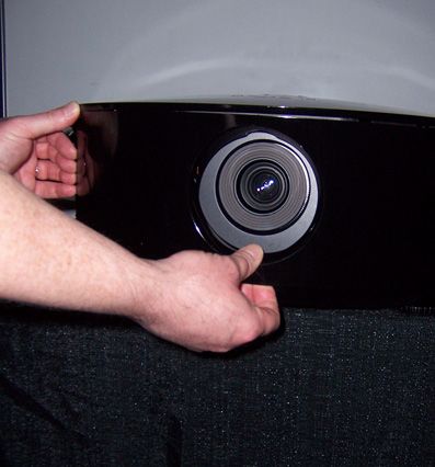
18. Do not operate lamps beyond the rated lamp life. Excessive operation of lamps beyond rated life could
    cause them to explode in rare occasions.
19. Never look directly into the lens when the lamp is on.

Compliance Information
DECLARATION OF CONFORMITY:

Manufacturer’s Name: Planar Systems, Inc.
Manufacturer’s Address: 1195 NW Compton Drive, Beaverton, OR 97006
 hereby declares that the products Model Numbers:

                                                 RY
PD7170
conform with the provisions of:
Council Directive 2004/108/EC on Electromagnetic Compatibility;
                                                A
EN 55022 “Limits and methods of measurements of radio interference characteristics of information technology
equipment” 1998;
                                          IN
EN 55024 “Limits and methods of measurements of immunity characteristics of information technology
equipment” 1998;
                    IM

  Including:
  • EN 61000-4-2 “Electromagnetic compatibility (EMC) Part 4: Testing and measurement techniques Section 2:
    Electrostatic discharge immunity test”
                 EL

  • EN 61000-4-3 “Electromagnetic compatibility (EMC) Part 4: Testing and measurement techniques Section 3:
    Radiated, Radio-Frequency, Electromagnetic Field Immunity Test”
               PR

  • EN 61000-4-4 “Electromagnetic compatibility (EMC) Part 4: Testing and measurement techniques Section 4:
    Electrical fast transient/burst immunity test”
  • EN 61000-4-5 "Electromagnetic compatibility (EMC) Part 4: Testing and measurement techniques Section 5:
    Surge immunity test"
  • EN 61000-4-6 "Electromagnetic compatibility (EMC) Part 4: Testing and measurement techniques Section 6:
    Conducted disturbances induced by radio-frequency fields immunity test"
  • EN 61000-4-8 "Electromagnetic compatibility (EMC) Part 4: Testing and measurement techniques Section 8:
    Conducted disturbances induced by power frequency magnetic fields immunity test"
  • EN 61000-4-11 "Electromagnetic compatibility (EMC) Part 4: Testing and measurement techniques Section
    11: Voltage dips, short interruptions and voltage variations immunity tests"
  And:
  • EN 61000-3-2 "Electromagnetic compatibility (EMC) Part 3, Section 2: Limits for harmonic current emissions
    (equipment input current up to and including 16 A per phase)" 2000;
  • EN 61000-3-3 "Electromagnetic compatibility (EMC) Part 3, Section 3: Limitations of voltage changes,
    voltage fluctuations and flicker in public low-voltage supply systems, for equipment with rated current up to
    and including 16 A and not subject to conditional connection" 1995;
Council Directive 2006/95/EC and amended by M1 and C1 on Low Voltage Equipment Safety;
EN 60950 “Safety of information technology equipment, including electrical business equipment”

Planar PD7170 Installation/Operation Manual             vii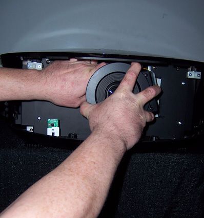
The Technical Construction file required by this Directive is maintained at the corporate headquarters of Planar
Systems, Inc., 1195 NW Compton Drive, Beaverton, OR 97006.
Date of Declaration: February 2008

FCC PART 15:

NOTE: This equipment has been tested and found to comply with the limits for a Class B digital device, pursuant
to Part 15 of the FCC Rules. These limits are designed to provide reasonable protection against harmful
interference in a residential installation.
This equipment generates, uses and can radiate radio frequency energy and, if not installed and used in
accordance with the instructions, may cause harmful interference to radio communications. However, there is
no guarantee that interference will not occur in a particular installation. If this equipment does cause harmful
interference to radio or television reception, which can be determined by turning the equipment off and on, the
user is encouraged to try to correct the interference by one or more of the following measures:

                                                  RY
• Reorient or relocate the receiving antenna.
• Increase the separation between the equipment and receiver.
• Connect the equipment into an outlet on a circuit different from that to which the receiver is connected.
                                                 A
• Consult the dealer or an experienced radio/TV technician for help.
                                         IN
INDUSTRY CANADA (ICES-003):
                  IM

This Class B digital apparatus complies with Canadian ICES-003.
Cet appareil numérique de la classe B est conforme à la norme NMB-003 du Canada.
               EL

IMPORTANT RECYCLE INSTRUCTIONS

         Lamp(s) inside this product contain mercury. This product may contain other electronic waste that can
             PR

         be hazardous if not disposed of properly. Recycle or dispose in accordance with local, state, or
         federal Laws.
         For more information, contact the Electronic Industries Alliance at WWW.EIAE.ORG.
         For lamp specific disposal information check WWW.LAMPRECYCLE.ORG.

DISPOSAL OF OLD ELECTRICAL AND ELECTRONIC EQUIPMENT (Applicable throughout the European Union and
other European countries with separate collection programs)

               This symbol found on your product or on its packaging, indicates that this product should not be
               treated as household waste when you wish to dispose of it. Instead, it should be handed over to
               an applicable collection point for the recycling of electrical and electronic equipment. By
               ensuring this product is disposed of correctly, you will help prevent potential negative
               consequences to the environment and human health, which could otherwise be caused by
               inappropriate disposal of this product. The recycling of materials will help to conserve natural
               resources. This symbol is only valid in the European Union. If you wish to discard this product, please
               contact your local authorities or dealer and ask for the correct method of disposal.

                                                          viii             Planar PD7170 Installation/Operation Manual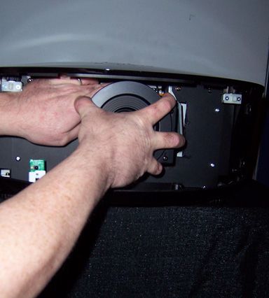
1.   Table of Contents
                               TWO YEAR LIMITED WARRANTY ......................................................................................iii
                               Important Safety Instructions ....................................................................................... vi
                               Compliance Information ..............................................................................................vii
                               1. Introduction .............................................................................................................. 1
                                    About This Manual .....................................................................................................1
                                          Target Audience ..................................................................................................1
                                          If You Have Comments About This Manual... ...................................................1

                                                           RY
                                          Textual and Graphic Conventions.....................................................................1
                                    Using This Manual .......................................................................................................2
                                    Description, Features and Benefits ..........................................................................3
                                                          A
                                          Key Features and Benefits...................................................................................3
                                              IN
                                          Parts List .................................................................................................................4
                               2. Controls and Functions ............................................................................................ 5
                  IM

                                    PD7170 at a Glance ..................................................................................................5
                                    PD7170 Rear Panel ....................................................................................................8
                                    PD7170 Remote Control ...........................................................................................9
               EL

                               3. Installation .............................................................................................................. 13
                                    Remote Control .......................................................................................................13
             PR

                                          Notes on Batteries ..............................................................................................13
                                          Notes on Remote Control Operation ..............................................................13
                                    Quick Setup ..............................................................................................................15
                                    Installation Considerations ......................................................................................16
                                          Installation Type..................................................................................................16
                                          Ambient Light .....................................................................................................17
                                          Throw Distance ...................................................................................................17
                                          Vertical and Horizontal Position........................................................................18
                                          Vertical and Horizontal Lens Shift .....................................................................19
                                          Folded Optics .....................................................................................................20
                                          Other Considerations.........................................................................................20
                                    Lens Replacement ..................................................................................................21

Planar PD7170 Installation/Operation Manual                             ix
Mounting the PD7170 ..............................................................................................23
              Floor Mounting (Upright) ...................................................................................23
              Ceiling Mounting (Inverted)..............................................................................23
              Adjusting the Projection Angle.........................................................................23
        Connections to the PD7170 ...................................................................................23
              Connector Panel Access ..................................................................................24
              Connecting Source Components to the PD7170 ..........................................25
              RS-232 Controller Connection ..........................................................................29
              Connecting 12-Volt Trigger Output to External Theater Equipment ............30
              Connecting an External IR Receiver................................................................30
              Connecting to AC Power .................................................................................31

                               RY
        Turning on the Power ..............................................................................................31
        Lens Adjustments .....................................................................................................31
              Focus ...................................................................................................................31
                              A
              Zoom....................................................................................................................31
                  IN
              Lens Shift..............................................................................................................31
        Changing the OSD Language ...............................................................................32
     IM

        Adjusting the Picture Orientation ..........................................................................33
              Rear Projection ...................................................................................................33
              Ceiling Mode ......................................................................................................33
  EL

   4. Operation ............................................................................................................... 35
        Selecting Video Memory ........................................................................................35
PR

        Selecting an Aspect Ratio ......................................................................................35
        Selecting An Input Source ......................................................................................35
        Using Picture-In-Picture (PIP) ...................................................................................36
        Using the On-Screen Menus ...................................................................................37
              Main.....................................................................................................................39
              Advanced...........................................................................................................49
              System .................................................................................................................55
              Control.................................................................................................................59
              Language ...........................................................................................................61
              Service.................................................................................................................62
   5. Maintenance and Troubleshooting ..................................................................... 65
        Lamp Replacement ................................................................................................65
        Troubleshooting Tips ................................................................................................66

                                           x                          Planar PD7170 Installation/Operation Manual
6. Serial Communications ......................................................................................... 69
RS-232 Connection and Port Configuration .........................................................69
Serial Command Syntax .........................................................................................69
Key Commands .................................................................................................69
Operations Commands ....................................................................................72
7. Specifications ......................................................................................................... 79
PD7170 Specifications .............................................................................................79
PD7170 Dimensions ..................................................................................................82
Supported Timings ...................................................................................................83
RY
A
IN
IM
EL
PR
Planar PD7170 Installation/Operation Manual xiNotes:
RY
A
IN
IM
EL
PR
xii Planar PD7170 Installation/Operation Manual1. List Of Figures
2-1. PD7170 Front/Side View ............................................................................................5
2-2. PD7170 Rear/Bottom/Top View................................................................................7
2-3. PD7170 Rear Panel ....................................................................................................8
2-4. PD7170 Remote Control............................................................................................9
3-1. IR Reception Angles ................................................................................................14
3-2. Estimating Throw Distance ......................................................................................17
3-3. Projector Placement ...............................................................................................18
RY
3-4. Vertical Lens Shift (Example Only) .........................................................................19
3-5. Horizontal Lens Shift (Example Only)......................................................................19
3-6. Folded Optics ...........................................................................................................20
A
3-7. HDMI/DVI Source Connections ..............................................................................25
IN
3-8. RGB Connections.....................................................................................................26
3-9. Component Video Connections ...........................................................................27
IM
3-10. Composite and S-Video Connections ................................................................28
3-11. RS-232 Control System Connection .....................................................................29
3-12. 12-Volt Trigger Output Connection .....................................................................30
EL
3-13. External IR Receiver Connection .........................................................................30
4-1. PD7170 OSD Menu Structure ..................................................................................38
PR
4-2. PD7170 Main Menu..................................................................................................39
4-3. Typical PLUGE Pattern for Adjusting Brightness ....................................................44
4-4. Typical Gray Bar Pattern for Adjusting Contrast...................................................44
4-5. Typical Test Pattern for Adjusting Sharpness .........................................................45
4-6. Overscan Examples.................................................................................................47
4-7. Source Select Sub-Menu.........................................................................................48
4-8. PD7170 Advanced Menu .......................................................................................49
4-9. RGB Adjust Sub-Menu .............................................................................................52
4-10. Fine Sync Sub-Menu ..............................................................................................53
4-11. PD7170 System Menu ............................................................................................55
4-12. Source Enable Sub-Menu .....................................................................................56
4-13. PIP and PBP areas for 720p Display......................................................................57
4-14. PIP Split-Screen Mode ...........................................................................................58
4-15. PD7170 Control Menu............................................................................................59
Planar PD7170 Installation/Operation Manual xiiiList Of Figures
4-16. PD7170 Service Menu............................................................................................62
7-1. PD7170 Dimensions ..................................................................................................82
RY
A
IN
IM
EL
PR
xiv Planar PD7170 Installation/Operation Manual1. Introduction
This Owner’s Manual describes how to install, set up and operate the Planar 1.1
PD7170 Home Theater Projector. About This Manual
Throughout this manual, the Planar PD7170 Home Theater Projector is referred to
as the “PD7170.”
Planar has prepared this manual to help home theater installers and end users Target Audience
get the most out of the PD7170.
Planar has made every effort to ensure that this manual is accurate as of the
RY
date it was printed. However, because of ongoing product improvements and
customer feedback, it may require updating from time to time. You can always
find the latest version of this and other Planar product manuals on-line, at
www.Planar.com.
A
Planar welcomes your comments about this manual. Send them to If You Have Comments
IN
info@Planar.com. About This Manual...
Text Conventions: The following conventions are used in this manual, in order to Textual and Graphic
IM
clarify the information and instructions provided: Conventions
• Remote and built-in keypad button identifiers are set in upper-case bold
type; for example, “Press EXIT to return to the previous menu.”
EL
• Computer input (commands you type) and output (responses that appear
on-screen) is shown in monospace (fixed-width) type; for example: “To
change the aspect ratio to Letterbox, type op aspect = 1 . ”
PR
• All keys with functional names are initial-capped, set in bold type and
enclosed in angle brackets. These keys are the following: ,
, , and .
• indicates that you may press either the RETURN or ENTER key on your
keyboard if it has both keys.
In addition to these conventions, underlining, boldface and/or italics are
occasionally used to highlight important information, as in this example:
A carriage return must be used after each command or
Note string.
Planar PD7170 Installation/Operation Manual 1Introduction
Graphic Conventions: These symbols appear in numerous places throughout
the manual, to emphasize points that you must keep in mind to avoid problems
with your equipment or injury:
TIPS highlight time-saving short cuts and helpful guidelines for
Tip using certain features.
NOTES emphasize text with unusual importance or special
Note significance. They also provide supplemental information.
Caution CAUTIONS alert users that a given action or omitted action
can degrade performance or cause a malfunction.
RY
WARNING WARNINGS appear when a given action or omitted action
can result in damage to the equipment, or possible non-fatal
injury to the user.
DANGER!
A DANGER appears when a given action can cause severe
injury or death.
IN
IM
1.2 Use the following table to locate the specific information you need in this
Using This Manual manual.
EL
If you need... ... Turn to page:
Information about obtaining service iv
PR
General information about the PD7170 Home Theater 3
Projector
Installation instructions 13
First-time configuration instructions 32
Advanced configuration instructions 49
Troubleshooting tips 66
Specifications for the PD7170 Home Theater Projector 79
2 Planar PD7170 Installation/Operation ManualIntroduction
The Planar PD7170 has been engineered for the top quality picture 1.3
performance and installation flexibility heretofore associated with projectors Description, Features
costing far more.
and Benefits
The PD7170 high-definition, 1280 x 720 native resolution, three-chip DLP™ light
engine features state-of-the-art technology for bright, pristine, high-definition
images.
The PD7170 is equipped with a precision optics package offering zoom, focus
and lens shift controls and a throw range of 1.82:1 to 2.28:1. For even greater
installation flexibility, four other lens options are available offering throw
distances ranging from 1.52 to 7.09 times the screen width.
The PD7170 has been engineered to comply with Imaging Science
Foundation™ (ISF) standards for maximum home theater image quality. Planar's
sophisticated parameters for white balance and color gamut control have also
RY
been implemented for precise balance of gray scale and color. The PD7170
incorporates proprietary de-interlacing technology that provides exceptional
scaling and film-to-video (3:2 pull-down) conversion for the most artifact-free
A
images possible.
Discrete infrared (IR) and RS-232 control make custom installation seamless,
IN
while discrete power on/off and source selection accommodate any
automation control system.
IM
The PD7170 offers these key features and benefits: Key Features and Benefits
• Native Resolution: 1280 x 720 (16:9 Native Aspect Ratio)
• DLP system using three (3), high-performance Digital Micromirror Device
EL
(DMD) chips for increased brightness, allowing for larger screen sizes
• DynamicBlack™ provides for infinitely variable adjustment of the light path
through the optics, enabling the perfect balance of black and white levels
PR
for any type of video source material
• Picture in Picture function allows you to display two inputs on the screen at
the same time
• Two (2), HDMI 1.3 Inputs with High-bandwidth Digital Content Protection
(HDCP)
• HDTV Compatible
• Power lens shift (horizontal and vertical)
• Power zoom and focus
Planar PD7170 Installation/Operation Manual 3Introduction
Parts List ➤ Your PD7170 is shipped with the following items. If any items are missing or
damaged, please contact your Planar dealer or Planar Customer Service at
(866) PLANAR1 (752-6271).
• PD7170 Home Theater Projector with standard Z100 Lens (1.82:1 – 2.28:1 throw
ratio; part number 997-5488-00)
• Remote Control Unit and two (2), AA-size batteries
• AC Power Cords (North America, Europe, United Kingdom)
• Source Connection Cables:
• Component Video, 1.8 meters (5.9 feet)
• HDMI to HDMI, 2.0 meters (6.6 feet)
• Warranty information and registration card
• Cleaning Cloth
• Clip-on Light Shield
RY
• Planar PD7170 Installation/Operation Manual (this document)
Optional Accessories:
• Ceiling mount kit (part number 997-4214-00)
A
• Replacement Lamp (part number 997-5353-00)
• Replacement Lenses (refer to page 18 for more information):
IN
• Z80, 1.52:1 – 1.82:1 throw ratio (part number 997-5487-00)
• Z200, 2.28:1 – 3.04:1 throw ratio (part number 997-5489-00)
IM
• Z400, 3.04:1 – 4.56:1 throw ratio (part number 997-5490-00)
• Z500, 4.56:1 – 7.09:1 throw ratio (part number 997-5491-00)
EL
PR
4 Planar PD7170 Installation/Operation ManualControls and Functions
2. Controls and Functions
Figure 2-1 and Figure 2-2 show the key PD7170 components. 2.1
PD7170 at a Glance
Top IR Sensor
Power Button/
Status LED
System Keypad
RY
Exhaust A
Vent Intake
Vent
IN
IM
Projection Lens
Front IR Sensor
EL
Figure 2-1. PD7170 Front/Side View
PR
• TOP IR SENSOR
Receives infrared signals from the remote control unit.
• SYSTEM KEYPAD
Provides an alternative to using the remote control unit to select a source or
navigate the on-screen display (OSD) controls. SOURCE
SOURCE ▲
Use this button to select a video source.
Cursor Buttons ( , , , ) ◄ ►
Use these buttons to select items or settings, adjust settings or switch display
patterns.
▲
MENU
Planar PD7170 Installation/Operation Manual 5Controls and Functions
ENTER ( )
Press to select a highlighted menu item or confirm a changed setting.
When no menu is present on-screen, press ENTER to access the motorized lens
focus control. Press ENTER again to access the motorized lens zoom control.
Press ENTER yet again to access the motorized lens shift control.
Use the and buttons to adjust focus, zoom or vertical lens position. Use
the and buttons to adjust horizontal lens position.
MENU
Press this button to show or hide the OSD menus.
• POWER BUTTON/STATUS LED
Indicates projector status as follows:
• Solid green = AC power present, ready to turn on (lamp not lit)
RY
• Flashing green = lamp is warming up or cooling down; keypad functions
not allowed
• Off = Lamp lit, projector functioning normally
A
• Alternating green/red = Lamp problem (door open, unable to strike, end
of life), user intervention likely to fix problem
IN
• Flashing red = Over temperature, user intervention (clear vents, turn on AC)
may fix problem
• Solid red = Error that requires servicing (fan fail, Power-on self-test fail etc.)
IM
• EXHAUST VENT
Warm air exits the projector through this vent. Ensure that it is not blocked.
• INTAKE VENT
EL
Internal fans draw cool air into the projector through this vent.
• PROJECTION LENS
The inside of the lens barrel is threaded to accommodate a standard, 72-mm
PR
lens filter. For example, with a smaller screen you can install a neutral-density
filter to reduce the overall light output.
If needed, a light shield accessory is provided with the lens to minimize stray
light emissions. (Use it only when the vertical offset is 50% of the screen height
or greater.) The light shield attaches to the end of the lens (or to the filter, if
used).
• FRONT IR SENSOR
Receives infrared signals from the remote control unit.
6 Planar PD7170 Installation/Operation ManualControls and Functions
1
2
RY
3 A
IN
4
IM
EL
5
PR
6
Figure 2-2. PD7170 Rear/Bottom/Top View
1. PLANAR LOGO BADGE
2. REAR COVER
Remove to access connectors.
3. LAMP MODULE COVER
Remove this cover to access the lamp compartment.
4. CABLE OPENING
Pass cables through this opening.
5. CEILING MOUNT HOLES
Use these to attach the ceiling bracket to the projector.
6. ADJUSTABLE FEET
Use these when the projector is installed in a table-top configuration to level
the image and/or adjust the projection angle.
Planar PD7170 Installation/Operation Manual 7Controls and Functions
2.2 Figure 2-3 shows the PD7170 rear panel.
PD7170 Rear Panel
(PD8150
only)
11 10 9 8 7 6 5
RY
1 A AC
2
IN
(PD8150
AC
3 4 only)
IM
Figure 2-3. PD7170 Rear Panel
1. HDMI 1 (Digital)
HDMI 2 (Digital)
EL
HDCP-compliant digital video inputs for connecting an HDMI or DVI source.
2. POWER INPUT (100 to 240 VAC)
Connect the PD7170 to power here.
PR
3. RGB
Provides a standard, 15-pin VGA-style connection to either an RGB or
component high-definition source, or to a personal computer. The PD7170
automatically detects the input signal resolution.
4. COMPONENT 2
Three BNCs for connecting component (YPbPr) video sources.
5. COMPONENT 1/SCART (RCA connectors)
Standard- or high-definition (480i/480p/576i/576p/720p/1080i/1080p)
Component (YPrPb) input for connecting a DVD/HD-DVD/BD player, HD
set-top box or other SD/HD source. Also provides RGB input for RGBS
sources.
6. VIDEO
Standard composite video input for connecting a VCR, laser disc player or
other composite video source. Also provides composite sync input for RGBS
sources.
8 Planar PD7170 Installation/Operation ManualControls and Functions
7. S-VIDEO
A standard S-Video input for connecting a DVD player, satellite receiver or
Super VHS (S-VHS) VCR.
8. IR INPUT
Wired input from a Niles- or Xantech-compatible, infrared (IR) repeater
system.
9. TRIGGER 2 (3.5-mm, mini phono jack)
Provides 12 (+/- 1.5) volt switched output for screen relays with 250mA
current capacity and short protection.
10. TRIGGER 1
Provides 12 (+/- 1.5) volt switched output for screen relays with 250mA
current capacity and short protection.
11. RS-232
A female, 9-pin D-sub connector for interfacing with a PC or home theater
automation/control system.
RY
Figure 2-4 shows the PD7170 remote control, and the paragraphs that follow 2.3
describe its functionality.
A PD7170 Remote Control
IN
ON POWER OFF
1 2
IM
l
SOURCE
1 2 3
3
EL
4 5
▲
4
PR ▲
▼
ENTER
▼
6 MENU
5
USER MEMORY
M1 M2 M3
7
SHARP
8 GAMMA OS NR
10 PIP SWAP LIGHT
9
Figure 2-4. PD7170 Remote Control
Planar PD7170 Installation/Operation Manual 9Controls and Functions
1. ON
Use this button to turn the projector on.
2. OFF
Use this button to turn the projector off.
3. Source Selection Buttons (1-5):
Press to select a video source. By default, these buttons are assigned as
follows: 1 = HDMI 1; 2 = HDMI 2; 3 = Component 1; 4 = S-Video; 5 = Video.
However, you can assign each button to any source you wish.
4. Cursor Buttons ( , , , )
Use these buttons to select items or settings, adjust settings or switch display
patterns.
ENTER
Press to select a highlighted menu item or confirm a changed setting.
RY
When no menu is present on-screen, press ENTER to access the motorized
lens focus control. Press ENTER again to access the motorized lens zoom
control. Press ENTER yet again to access the motorized lens shift control.
A
Use the and buttons to adjust focus, zoom or vertical lens position. Use
IN
the and buttons to adjust horizontal lens position.
5. Aspect Ratio Selection Button
Press this button repeatedly to select one of the following aspect ratios:
IM
16 : 9: For viewing 16:9 DVDs or HDTV programs in their native aspect ratio.
Letterbox: For viewing LaserDisc movies or non-anamorphic DVDs on a 16:9
screen.
EL
4 : 3: Scales the input signal to fit 4:3 sources in the center of the screen.
4:3 Narrow: Scales the input signal to fit 4:3 sources in the center of the
screen when using an anamorphic lens.
PR
Native: Displays source image in its native resolution without re-sizing or
overscan.
6. MENU
Press this button to show or hide the OSD controls.
7. Memory Preset Buttons (M1 / M2 / M3)
Press to recall settings for the current input from one of three memory
presets. By default, these buttons are assigned as follows: M1 = User
Memory 1; M2 = User Memory 2; 3 = ISF Night. However, you can assign each
button to any memory preset you wish.
10 Planar PD7170 Installation/Operation ManualControls and Functions
8. Picture Adjustment Buttons:
Contrast
Press to adjust white level.
Brightness
Press to adjust black level.
Sharpness (SHARP)
Press to adjust sharpness.
Gamma (GAMMA)
Press to select a gamma curve.
Overscan (OS)
Press to select an overscan mode.
Noise Reduction (NR)
Press to adjust noise reduction level.
9. LIGHT
Press momentarily to activate remote backlighting. Press and hold for
RY
5 to 7 seconds to illuminate the projector rear panel, to facilitate
connecting cables in a dark room.
10. Picture-In-Picture (PIP) Controls: A
PIP
Press repeatedly to activate/deactivate PIP mode or select the desired PIP
IN
image source.
SWAP
IM
Press to swap the PIP image with the active source image.
EL
PR
Planar PD7170 Installation/Operation Manual 11Controls and Functions
Notes:
RY
A
IN
IM
EL
PR
12 Planar PD7170 Installation/Operation ManualInstallation
3. Installation
To install batteries in the remote control: 3.1
1. Slide the battery compartment cover in the direction of the arrow to Remote Control
remove it.
2. Install two AA batteries with the correct polarity.
3. Replace the cover.
1. 2. 3.
RY
A
IN
• Make sure that the battery polarities are correct when installing the batteries. Notes on Batteries
• Do not mix an old battery with a new one or different types of batteries.
IM
• If you will not use the remote control for a long time, remove the batteries to
avoid damage from battery leakage.
EL
• In most situations, you can simply point the remote control at the screen Notes on Remote Control
which will reflect the IR signal from the remote back toward the IR receiver on Operation
the projector. In some cases, however, ambient conditions may prevent this.
PR
If so, point the remote control at the projector and try again.
• If the effective range of the remote control decreases, or it stops working,
replace the batteries with new ones.
• The remote control may fail to operate if the infrared remote sensor is
exposed to bright sunlight or fluorescent lighting.
Planar PD7170 Installation/Operation Manual 13Installation
• The projector’s front IR receiver has a range of approximately 40 feet (12.19
meters); the top IR receiver has a range of approximately 20 feet (6.10
meters). Figure 3-1 shows the reception angles of the front and top IR
receivers.
90.0°
RY
90.0°
135.0°
A
IN
IM
Figure 3-1. IR Reception Angles
EL
PR
14 Planar PD7170 Installation/Operation ManualInstallation
Table 3-1 gives a quick overview of the PD7170 installation process. The sections 3.2
following this one provide detailed instructions. Quick Setup
Installation should be performed by a qualified custom
Note video installation specialist.
Table 3-1. Installation Overview
For Details, Refer to
Step Procedure
page...
1 Choose a location for the projector 16
RY
2 Install the projection lens (if standard lens will not be 21
used)
3 Mount the projector
A 23
4 Connect signal sources to the PD7170 25
IN
5 Connect external controller to RS-232 port and/or IR 29
repeater system (optional)
IM
6 Connect 12-volt trigger output to retractable screen 30
or other, +12V trigger-activated equipment
(optional)
EL
7 Apply power to the projector 31
8 Primary lens adjustments: projected image size 19, 31
PR
(zoom), position (shift) and focus
9 Change the OSD Language (optional) 32
10 For rear-screen and/or ceiling-mount installations, 33
select the proper picture orientation
11 Projector calibration: adjust the following for each 39
input; save settings when finished:
Aspect ratio
Brightness
Contrast
Color level
Tint
Input position
Planar PD7170 Installation/Operation Manual 15Installation
3.3 Proper installation of your projector will ensure the quality of your display.
Installation Whether you are installing a projector temporarily or permanently, you should
take the following into account to ensure your projector performs optimally.
Considerations
Installation Type ➤ Choose the installation type that best suits your needs: front or rear screen, floor
mount or inverted mount. Table 3-2 compares these various installation
methods.
Table 3-2. Projector Installation Options
Advantages Considerations
Front Screen, Floor Mount Installation
RY
• Easy to set up • Shares floor space with audience
• Can be moved or changed quickly
• Easy to access
Front Screen, Inverted Mount (ceiling) Installation
A
• Does not take up audience space • Installation is more permanent
IN
• Projector is unobtrusive • Projector access is more difficult
• Projector cannot be accidentally
moved
IM
Rear Screen, Floor Mount Installation
• Projector is completely hidden • Requires separate room
• Projector is easily accessed • Installation cost is usually higher
EL
• Usually good ambient light rejection
Rear Screen, Inverted Mount (ceiling) Installation
PR
• Projector is completely hidden • Requires separate room
• Usually good ambient light rejection • Installation cost is usually higher
Rear Screen, Floor Mount with Mirror
• Projector is completely hidden • Requires separate room
• Usually good ambient light rejection • Installation cost is usually higher
• Requires less space behind screen than
other rear screen installations
16 Planar PD7170 Installation/Operation ManualInstallation
In general, minimize or eliminate light sources directed at the screen. Contrast Ambient Light
ratio in your images will be noticeably reduced if light directly strikes the screen,
such as when a shaft of light from a window or floodlight falls on the image.
Images may then appear washed out and less vibrant.
Throw distance is the distance measured from the front of the projector to the Throw Distance
screen. This is an important calculation in any projector installation as it
determines whether or not you have enough room to install your projector with
a desired screen size and if your image will be the right size for your screen.
You can quickly estimate the throw distance by taking the width of the screen
and multiplying it by the lens throw ratio; see Figure 3-2. The result of this
calculation tells you roughly how far back the projector should be positioned
from the screen in order to project a focused image large enough to fill the
screen.
RY
Estimating Throw Distance
Throw Distance (TD) =
Screen Width (w) x Lens Throw Ratio
A Scr
een
wid
th (
w)
IN
IM
TD
EL
PR
Figure 3-2. Estimating Throw Distance
Planar PD7170 Installation/Operation Manual 17Installation
Table 3-3 lists the available lens options for the PD7170 and their associated
throw ratios.
Table 3-3. PD7170 Lens Options and Throw Ratios
Throw Range in inches, with a 96x54-inch
Lens Option Throw Ratio (1.78:1) Screen
Minimum Maximum
Z80 1.52 - 1.82 145.92 174.72
Z100 (standard) 1.82 - 2.28 174.72 218.88
Z200 2.28 - 3.04 218.88 291.84
Z400 3.04 - 4.56 291.84 437.76
Z500 4.56 - 7.09 437.76 680.64
RY
Vertical and Horizontal ➤ Proper placement of the projector relative to the screen will yield a rectangular,
Position perfectly-centered image that completely fills the screen.
A
Ideally, the projector should be positioned perpendicular to the screen and in
such a way that the lens center is aligned with either the top or bottom edge of
IN
the screen area, and centered horizontally. See Figure 3-3.
IM
Ceiling Installation
Ceiling
Height Projection Distance
EL
x
Lens Center Lens Center
PR
Screen
Floor Installation
Height Screen
Lens Center
Lens Center
x
Projection Distance
Floor
Figure 3-3. Projector Placement
18 Planar PD7170 Installation/Operation ManualInstallation
You can use the lens shift controls on the projector to center the image on the Vertical and Horizontal
screen. Lens shift is generally expressed as a percentage of the screen height or Lens Shift
width, as shown in Figure 3-4 and Figure 3-5.
Screen Center
0%
50% Height
Lens Shift
(0.5 x H)
100% Height
Lens Shift
(1.0 x H)
RY
Note: This is a general example of lens shift. Lenses vary in their shift capabilities. No
particular lens or projector is used in this example.
Figure 3-4. Vertical Lens Shift (Example Only)
A
IN
100% Width Lens Shift
(1.0 x W)
IM
50% Width Lens Shift
(0.5 x W)
EL
Screen Center
0%
PR
Screen Width (W)
Note: This is a general example of lens shift. Lenses vary in their shift capabilities. No
particular lens or projector is used in this example.
Figure 3-5. Horizontal Lens Shift (Example Only)
Planar PD7170 Installation/Operation Manual 19Installation
Vertical Lens Shift: The PD7170 provides up to 65% of vertical lens shift up or
down. For example, with a 100 x 56 inch (1.78:1) screen, you can shift the image
up to 36.40 inches (0.92 meters) above or below the screen center.
Horizontal Lens Shift: The PD7170 provides up to 30% of horizontal lens shift left or
right. For example, with a 100 x 56 inch (1.78:1) screen, you can shift the image
up to 30.00 inches (0.76 meters) left or right of the screen center.
1. With no vertical or horizontal lens shift, the lens center and
Note screen center are aligned with each other.
2. Vertical shift limits are percentages of the screen height.
Horizontal shift limits are percentages of the screen width.
3. Vertical lens shift figures are for ceiling mount
configurations. For floor installations (where the projector
is upright), reverse the up/down vertical lens shift
RY
percentages.
Folded Optics ➤ In rear-screen applications where space behind the projector is limited, a mirror
A
may be used to fold the optical path, as shown in Figure 3-6. The position of the
projector and mirror must be accurately set. If you are considering this type of
installation, contact your dealer for assistance.
IN
Screen
IM
Mirror
EL
PR
Figure 3-6. Folded Optics
Other Considerations ➤ Other considerations and tips that can help improve your installation:
• Keep the ambient temperature constant and below 35°C (95°F). Keep the
projector away from heating and/or air conditioning vents. Changes in
temperature may cause drifts in the projector circuitry, which may affect
performance.
• Keep the projector away from devices that radiate electromagnetic energy
such as motors and transformers. Common sources of these include slide
projectors, speakers, power amplifiers and elevators.
20 Planar PD7170 Installation/Operation ManualInstallation
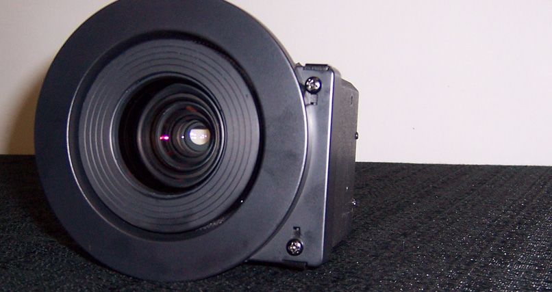
The PD7170 is shipped with the standard (1.82 – 2.28) projection lens 3.4
pre-installed. If your installation requires a different lens, proceed as follows to Lens Replacement
remove the standard lens and replace it with the required one.
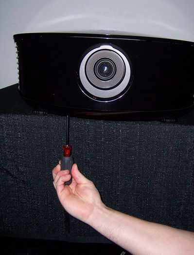
1. Using a Phillips screwdriver,
remove the two screws holding
the projector front cover in place.
2. Gently pull the cover away from
RY
the projector at each side to
A
detach it.
IN
IM
EL
3. Remove the cover and set it aside.
PR
4. Locate the lens release lever, above the lens cavity.
Planar PD7170 Installation/Operation Manual 21Installation
5. Press and hold the lens release
button. Then, grasp the lens by the
front and rotate it
counterclockwise until it stops
(approximately 30 degrees).
6. Pull the lens straight out to remove it.
RY
7. Remove the trim ring attached to
A Trim Ring
the motor housing on the lens you
just removed. To do this, remove
the two screws and two metal
IN
clips that hold it in place.
IM
8. Attach the trim ring to the motor
housing on the new lens.
EL
9. Note that the lens mount flange
has a female socket connector for
the lens motor on the right side of
PR
the flange. (The lens assembly Lens Motor
motor has a male socket Connector
connector that mates with this
connector.)
10. Hold the replacement lens assembly with the motor facing to the right.
Carefully insert the back of the lens assembly into the hole in the lens flange.
11. Slightly rotate the lens assembly counterclockwise to align the motor
connectors on the lens and lens flange. Gently push the lens assembly in
until it is seated flush against the flange and the motor connectors have
seated.
12. Carefully rotate the lens assembly clockwise until it stops and the metal clips
at the back of the lens “click” into place.
13. Replace the projector front cover.
22 Planar PD7170 Installation/Operation ManualYou can also read