Green revolution in electronic displays expected to ease energy and health crises - Nature
←
→
Page content transcription
If your browser does not render page correctly, please read the page content below
Wang et al. Light: Science & Applications (2021)10:33                                                                                       Official journal of the CIOMP 2047-7538
                                    https://doi.org/10.1038/s41377-020-00455-9                                                                                                                       www.nature.com/lsa

                                     PERSPECTIVE                                                                                                                                                Open Access

                                    Green revolution in electronic displays expected to
                                    ease energy and health crises
                                    Yuyang Wang1, Hui Nie2, Jinsong Han3, Yaxun An4, Yu-Mo Zhang                                                      1
                                                                                                                                                          and Sean Xiao-An Zhang                       1

                                      Abstract
                                      The technological revolution of long-awaited energy-saving and vision-friendly displays represented by bistable
                                      display technology is coming. Here we discuss methods, challenges, and opportunities for implementing bistable
                                      displays in terms of molecular design, device structure, further expansion, and required criteria, hopefully benefiting
                                      the light-related community.

                                      With the rapid advancement of the internet, electronic                                            considerations of the design principles and strategies for
                                    information and globalization, electronic displays have                                             further development of green technology, especially
                                    revolutionized our lives1–3. Although they bring us                                                 focusing on how to solve the challenges and bottlenecks
                                    amazing visuals and real-time information acquisition, the                                          faced by current EC materials and devices. Moreover, we
                                    issues caused by their long-term use and subsequent                                                 will propose some suggestions based on cross-fusion
                                    waste, such as very high energy consumption, high related                                           strategies to help overcome the current status of con-
                                    pollution, low energy utilization efficiency, and eye                                                tinuous power consumption in mainstream light-emitting
                  1234567890():,;
1234567890():,;
                  1234567890():,;
1234567890():,;

                                    damage, are also becoming increasingly prominent.                                                   display technology so that this technology also exhibits a
                                    Therefore, the development of low energy consumption                                                highly energy-efficient bistable performance. By doing so,
                                    and user-friendly electronic displays has become a long-                                            we hope to inspire an increasing number of researchers to
                                    term goal for future global sustainable development.                                                work together, to challenge many “impossible”, scientifi-
                                      Various electronic materials with bistable characteristics                                        cally forbidden areas through unconventional design
                                    that have emerged in recent years have aroused people’s                                             methods that eliminate inertial thinking.
                                    hope and excitement for energy-saving and user-friendly
                                    displays. Significant progress has been made in relevant                                             Bistable displays: promising power-saving display
                                    organic or inorganic electrochromic (EC) materials, and                                             techniques
                                    some bistable electronic materials/technologies have                                                  How can the need for rapid economic and social
                                    begun to enter the display market. New design principles                                            development be met without aggravating harm to the
                                    based on the proton-coupled electron transfer (PCET)                                                natural environment and health? The development of low
                                    mechanism and related bistable electronic materials are                                             energy consumption and more user-friendly electronic
                                    bringing energy-saving displays into an era where the                                               displays is the key. Light absorption and reflection are
                                    comprehensive performance is closer to the actual                                                   utilized by nature for color display and environmental
                                    application needs. Here we will focus on the key                                                    integration. The history of biological evolution proves that
                                                                                                                                        this is the best approach to utilize and transform external
                                                                                                                                        energy (light) (with the lowest energy consumption and
                                    Correspondence: Yu-Mo Zhang (zhangyumo@jlu.edu.cn) or Sean Xiao-
                                                                                                                                        the most efficient energy conversion). Therefore, “mate-
                                    An Zhang (seanzhang@jlu.edu.cn)
                                    1
                                     State Key Laboratory of Supramolecular Structure and Materials, College of                         rials and technology for reflective displays” open another
                                    Chemistry, Jilin University, Changchun 130012, China
                                    2
                                                                                                                                        door for the development of electronic displays for
                                     Department of Chemistry and Biochemistry, University of California, Santa
                                                                                                                                        humans. Such technology does not emit light itself but
                                    Barbara, Santa Barbara, California 93106, USA
                                    Full list of author information is available at the end of the article                              uses sunlight or external light sources to illuminate the
                                    These authors contributed equally: Yuyang Wang, Hui Nie

                                    © The Author(s) 2021
                                                        Open Access This article is licensed under a Creative Commons Attribution 4.0 International License, which permits use, sharing, adaptation, distribution and reproduction
                                                        in any medium or format, as long as you give appropriate credit to the original author(s) and the source, provide a link to the Creative Commons license, and indicate if
                                    changes were made. The images or other third party material in this article are included in the article’s Creative Commons license, unless indicated otherwise in a credit line to the material. If
                                    material is not included in the article’s Creative Commons license and your intended use is not permitted by statutory regulation or exceeds the permitted use, you will need to obtain
                                    permission directly from the copyright holder. To view a copy of this license, visit http://creativecommons.org/licenses/by/4.0/.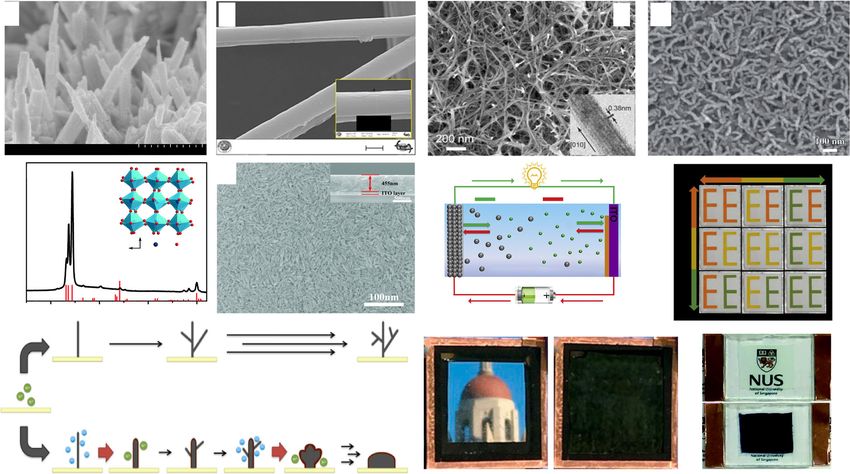
Wang et al. Light: Science & Applications (2021)10:33                                                                                                                            Page 2 of 14

                a     Transmittance (%)
                                                                              c                                 350
                                                                                                                            Salescaster Corp.
                                                                                                                300         76″×12″ LED sign

                                                                              Energy consumption (J•cm–2 h–1)
                                           Power off
                                                                                                                                      LED authority
                       Power on                                                                                 250                 36″×60″ LED sign
                                                       Power on

                       Power off                       Power off   Time (h)
                                                                                                                200   Corn Digital 42″
                                                                                                                                                 Hewlett-Packard
                                                                                                                       LCD Display
                b                                                                                               150
                                                                                                                                                 47″ LCD Display
                      Energy
                                    m le
                                 ste a b

                                                                                                                100
                               sy bist
                                 n-

                                                                                                                                                                   Bistable
                            No

                                                                                                                 50                                             electrochromic
                                                                                                                              Electrowetting display
                                                                                                                                                       CLC Display display
                                    Bistable system                                                               0                         E-ink display

                                      Reaction coordinate

 Fig. 1 Characters of the bistable display technologies. a Optical characteristics of a bistable display. b Characteristics of bistable materials at the
 molecular energy level. (A stands for original state of the molecule, B and C stand for different final states of the molecule). c Comparison of energy
 consumption for different electronic displays. The energy consumption of commercialized LCDs and LEDs contains both display and heat dissipation
 energy consumption

display. This might require very little electric drive to                                                        under an external voltage, resulting in a system change
switch pages without consuming additional power to                                                               between two states, including light and dark states.
continuously display information or images—chameleon-                                                            Nevertheless, CLCs usually act as light shutters. Without
like “bistable” characteristics (Fig. 1a, b). This means that                                                    the help of color filters or continuously changing back-
such strategies can greatly reduce the power and heat                                                            ground light, it is very difficult to achieve multicolors,
consumption of digital displays compared to mainstream                                                           which is inconsistent with an ideal energy-saving dis-
displays (Fig. 1c), which provides a solid foundation for                                                        play15. In EW, a highly promising display technology, an
future low-energy displays. More importantly, the                                                                electric field drives changes in the wettability and contact
“reflective display” has a natural color mode (light scat-                                                        angle of ink droplets on insulating substrates to display
tering type) that human beings are inherently familiar                                                           information, thereby regulating the diffusion and con-
with and gives users more adaptive color softness and eye                                                        traction of ink droplets by a voltage. The color pixel
comfort. The pioneering reflective display techniques                                                             response time is very fast (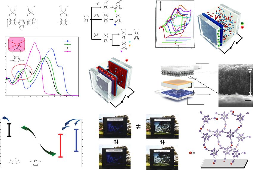
Wang et al. Light: Science & Applications (2021)10:33                                                          Page 3 of 14

structure caused by electron transfer; inorganic materials     the embedding/de-embedding cation with a triple charge-
represented by WO3, NiO, and so on, which exhibit color        balancing ability. This improvement endows the EC sys-
variations together with crystal structure changes due to      tem with impressive cyclic reversibility (2000 cycles) and a
electron transfer and ion migration; and organic–metallic      good bistability property (no obvious attenuation within
hybrid materials represented by Pt, Os, and Ir complexes,      1 h)36,37. Here, diffusion of Al3+ into the m-WO3-x lattice
which exhibit color changes caused by electron transfer        benefits from the smaller radius of Al3+, and the stronger
from metal ions to ligands. Among known promising EC           electrostatic effect between the ions and host lattice
materials, inorganic materials, mainly referring to inor-      contributes to the stable existence of the ions in the host
ganic transition metal oxides represented by WO323,24,         lattice.
have been widely studied. When a voltage stimulation is           It is worth mentioning that improving the energy effi-
applied, WO3 undergoes reduction/oxidation, accom-             ciency during the color switching process is also quite
panied by embedding/de-embedding of cations in its             meaningful for energy savings, because the current ECDs
crystal lattice, thereby changing the crystal structure and    still require external voltages to trigger color switching.
color of WO3. Under electrical stimulation, a reversible       Another effective strategy to save energy is to exploit new
color change of WO3 from colorless to blue can be              ECD structures, such as EC batteries, by utilizing hybrid
achieved. The reaction can be described as follows:            Zn2+/Al3+-based electrolytes and WO3 electrodes that
                                                               can retrieve power during the EC process17,18 (Fig. 2g).
    WO3 þ xMþ þ xe ! Mx WO3                                   Moreover, many beneficial attempts have also been made
                                                               to solve the shortcomings of the limited color variation,
  These inorganic materials have many advantages, such         such as via the color overlay effect of two segments of a
as good chemical stability, fatigue resistance, and an         sodium vanadium oxide electrode or incorporation of a
acceptable optical memory (OM) effect, while still facing      plasmochromic metal–insulator–nanohole cavity, a pho-
the following urgent challenges to be solved: high fabri-      tonic Fabry–Perot nanocavity, or others to achieve mul-
cation cost, poor structure modifiability, limited color        ticolor displays13,38 (Fig. 2h). Although significant
selection, low pure color quality, slow response rate, and     progress has been made in inorganic EC materials thus
unsatisfactory contrast. All these issues are related to the   far, the aforementioned technical bottlenecks are still
transport kinetics of both electrons and ions involved in      insurmountable and become the key factor restricting
the EC processes, which are affected by the morphology         their true entry into electronic displays (Fig. 2i).
and fabrication of the EC film. To solve these limitations,        Controlling the transmittance change of a device
versatile methods have been developed to prepare mate-         through reversible metal deposition and ionization dis-
rials, including thermal evaporation, laser ablation, sput-    sociation is another strategy to achieve bistable EC win-
tering, chemical vapor deposition, spray pyrolysis,            dows39–41. The working mechanism is as follows: metal
electrodeposition, sol-gel techniques, etc.25–28. Further-     ions are dissolved in a solution with a transparent original
more, various nanomaterials, such as EC thin films con-         state and then reduced to metal atoms by electrical sti-
taining nanoparticles, nanorods, and nanowires29,30 (Fig.      mulation, and a thin film of metal atoms is deposited on
2a–d), have been realized via simpler and easier methods.      the device surface that affects the transmission of visible
These advancements not only reduce the cost but also           light, resulting in each atom acting as a chromophore and
greatly improve the response speed, cyclic reversibility,      jointly affecting the transmittance change of the device. A
memory effect, and other performance parameters31. The         large transmittance change could be induced with a small
satisfactory phenomenon benefits from the enlarged              thickness EC film due to its dense chromophores. Com-
contact area between the electrodes and active species, the    pared with the traditional EC film, which usually needs to
enhancement of ion migration kinetics, and the electro-        be 100–1000 nm thick, the atomic deposition metal film
static effect of cations and EC materials. Meanwhile, by       only needs to be 20–30 nm thick, to achieve sufficiently
optimizing the electrolyte among the conductive layer and      good transmittance changes with excellent chemical sta-
the redox active substance in the ion storage layer, the       bility and resistance to ultraviolet (UV) degradation.
enhancement of the stability of cations in the host lattice    McGehee and coworkers demonstrated a different design
of the EC material also helps improve the bistable per-        of bistable ECDs by reversibly reducing Bi and Cu metal
formance. Mortimer and colleagues32–35 have performed          ions, and depositing them on modified ITO to obtain
excellent pioneering works in this field. Recently, oxygen-     relatively good performance (Fig. 2j, k). Precisely, due to
deficient monoclinic tungsten oxide nanowires (m-WO3-x          the morphology of the deposited Bi atom, they obtained
NWs) were used as EC materials (Fig. 2e, f). In the process    an ideal black display and its coloration state could be
of their reversible oxidation state change, Al3+, with a       maintained for 25 h without a continuous power sup-
small ion radius and a multicharge character, was selected     ply42,43. However, the known systems with reversible ion
to replace traditional corrosive H+ and higher cost Li+ as     electrodeposition of Ag, Cu-Pt, and Cu-Ag currently have
Wang et al. Light: Science & Applications (2021)10:33 Page 4 of 14
a b c d
Pa1=2.193 µm
Pb1=266.3°
Signal A = SE1 EHT = 20.00 KV 2 µm
Mag = 5.00 KX
SU8020 5.0kV 7.3mm ×80.0k SE(U) 500nm WD = 11.0 mm I Probe = 50 pA
e f g Discharge Coloration
h
(200)
m-WO3-x 2.0 V 1.2 V 0.2 V
e– e–
Discharge Charge
2.0 V
(020)
Cathode (WO3)
Anode (Zn)
lntensity
Zn2+ AI3+
a
(002)
1.2 V
b c W O
(202)
(140)
Zn2+/AI3+-based electrolyte
0.2 V
e– e–
20 30 40 50
Charge Decoloration
2 (°)
k j i
Fig. 2 Latest developments in various inorganic electrochromic materials and devices. a Scanning electron microscopy (SEM) image of WO3
nanorods79. b SEM image of PPy/WO3/BMIMBF4 nanofibers80. c Typical SEM image of a WO3 sample manifesting a nanowire morphology37. d SEM
image of an electrodeposited WO3 film on ITO glass33. e Structure and morphology characterization of m-WO3-x nanowires36. f Digital photo of an
electrochromic device assembled from an m-WO3-x nanowire working electrode36. g Scheme of the rechargeable hybrid Zn2+/Al3+ electrochromic
battery17. h Multicolor electrochromic display based on a SVO electrode38. i Electrochromic device assembled by an m-WO3-X nanowire working
electrode and an ITO glass counter electrode36. j Hybrid dynamic windows using reversible metal electrodeposition42. k Reaction schematic showing
the electrodeposition of Bi in the absence and presence of Cu. Green and blue circles represent Bi3+ and Cu+ ions participating here42
disadvantages in terms of durability and toxicity, espe- Recently, great attention has been paid to improving the
cially when Pt ions are involved. In addition, the limited device bistability. The known effective strategies are
color selection, low pure color quality, and slow switching summarized as follows:
speed restrict their potential application in electronic (a) Controlling the spontaneous charge transfer can
displays. avoid OM loss in the V-Off state, which is an
Organic EC materials, mostly conjugated polymers, effective method proposed by Kim and colleagues50
have also been reported to enable bistable displays44–46. to improve the material bistability. Although there
Usually, the applied voltage adjusts the energy level of the are multiple interfaces in an ECD (i.e., Indium Tin
subunits of the redox polymer, thereby changing the Oxide (ITO) electrode/EC film/electrolyte/ITO
characteristics of its absorption spectrum and visually electrode), fundamentally speaking, the OM loss is
showing a color change. The concepts of “band gap mainly related to the charge transfer at the interface
engineering” and the “donor–acceptor” approach have of ITO and the EC film. It is greatly affected by the
proven to be good design principles in using π-conjugated energy levels of the EC polymer. For example,
polymers for photoelectric devices thus far (Fig. 3a). different substituents on the polythiophene skeleton
Reynolds and coworkers47–49 have made great pioneering affect its oxidation potential (Eox) and highest
contributions to the field. By modifying the electron- occupied molecular orbital (HOMO) energy levels
withdrawing/-pushing groups on the polymer backbone, by changing the dynamic microstructural alterations/
full spectral (color) control can be achieved. Compared supramolecular stabilization/ionization/interactions
with inorganic EC materials, polymer materials have the and electron/charge transfer within and between
advantages of light weight, low cost, flexibility, good film- the polymer chains51,52. In general, an electron-
forming ability, and low energy consumption for pre- withdrawing group increases Eox and an electron-
paration. Hence, these polymer materials hold great pushing group decreases Eox (Fig. 3b). Recently, by
potential for future flexible and wearable displays. modifying polythiophene with different substituents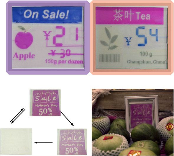
Wang et al. Light: Science & Applications (2021)10:33 Page 5 of 14
a b Cl
Cl Cl c
O O
R R R R R
O O
SCP 1x10⁻⁴ A/cm2 te
oly
R HO OH
O O O O O O
ctr
Ele
p-TSA / S S n
toluene PE-Cl
O O O O O O O O HO OH O O SCP O O
m=1, P7 p-TSA /
S S
m=2, P8 S
P10 S
toluene S S
PR-Me
n
Electron
m m (1)
n m=3, P9 n
Dopant ion
N N R R R R
S O O O O ITO
Br Br Br Br ROH SCP
R = 2-EthylHexyl electrode
CPs
R = 2-EthylHexyl O O O O
NaH
90,000 HO OH O O DMF S
R S
R n
O O P7 p-TSA /
S
Br Br
PR-MeO (R = Methyl)
80,000
Absorption coefficient (cm–1)
toluene SCP
P8 O O PR-EHO (R = 2-ethylhexyl) EPOX
P9 V-off
70,000 P10
S
PR-Br
n
–1.0 –0.5 0.0 0.5 1.0 1.5
O O Potential (V)
60,000
d Electrical Dopant ion e CE : FTO
50,000 S double layers
40,000
30,000 TNP (t3)
20,000 TNP
ITO BMIL (t2)
CPs
10,000 electrode
PR-Br (t1)
0
300 400 500 600 700 800 900 V-off µm
1µ
WE : ITO
Wavelength (nm)
f e–
g h
e– –2.0
–3.0
–3.19 eV e– Ox.
A– C+ A– e– –0.5 V
A– C+ 0.23 V Red.
A– C+ A– 0.0
Vacuum / eV
E vs. NHE / V
–5.0 C+ C+
–5.02 eV + A– C+
C V-On V-Off V-On V-Off
PR-Br A– A– C+ 2.0
–7.0
Electrolyte A– C+
PdCl2
A– = C+ =
2.7 V V-Off
O – O
3.55 V TiO2
S
N
S H3C +
N N
(CH2)3CH3 4.0 state
–9.0 F3C CF3 PW12 TCO
OO
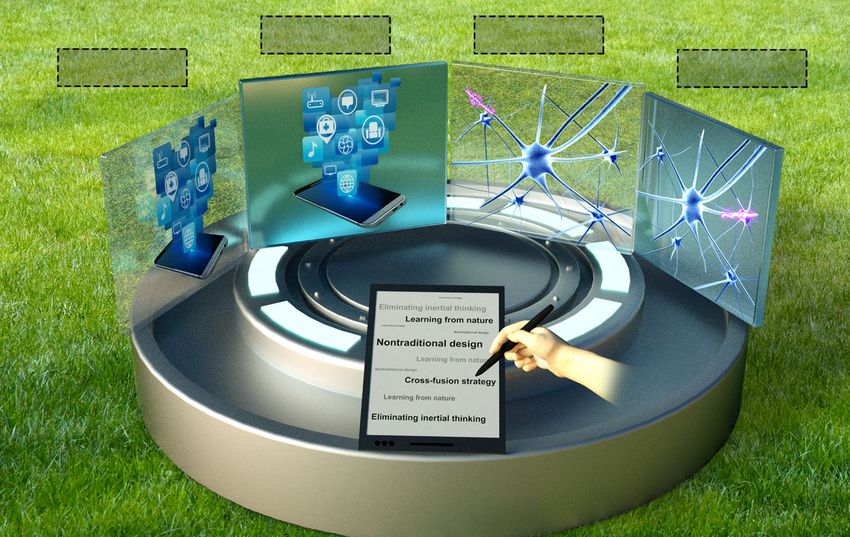
Fig. 3 Latest developments in various organic electrochromic materials and devices. a Spectral regulation of conjugated polymers based on
the “donor–acceptor” approach48. b Synthetic routes and structure for EC polymers, including PE-Cl, PR-Me, PR-MeO, PR-EHO, and PR-Br, based on the
“donor–acceptor” approach, and the corresponding cyclic voltammograms50. c Schematic diagram of the interfacial electron transfer between ITO
and an EC polymer50. d Schematic diagram of the electrical double layers formed by dopant ions50. e Schematic diagram of an EC device containing
a TiO2 layer (BMIL, 1-butyl-3-methylimidazolium bis(trifluoromethylsulfonyl)imide; WE, working electrode; CE, counter electrode; RE, reference
electrode)55. f Mechanism of the charge-balancing effect of the ion storage layer containing TiO2 and PW1156. g Photographic images of bistable
electrochromic windows50. h Schematic diagram of the assembly process of organic–metallic hybrid EC materials. TCO, transparent conducting
oxide22
(including electron-withdrawing (Br, Cl) and bulky Electrochromism of known selenophene polymers
(2-ethylhexyl) side groups), the HOMO level of the occurs in the near-infrared region outside the visible
polythiophene structure was adjusted below the region with good OM characteristics in the colored
Fermi level of the ITO electrode (EF, −4.7 V), thus state. The undesirable color range and good OM are
avoiding spontaneous electron migration between the due to the large atomic radius of the selenium atom
polymer and the electrode. This is critical to stabilize (Se), which increases the structural hindrance and
the polymer state and avoid self-bleaching of its supramolecular interactions, thus improving the
color. When the EHOMO of the EC polymer is higher structural stability of related polymer aggregates in
than the EF of the ITO electrode, undesirable the EC state to resist thermal disturbances. On the
interfacial electron transfer (IET) usually occurs other hand, thiophene-based polymers with smaller
reversibly from the EC polymer back to ITO. If the atomic radius sulfur atoms show a large change in
potential difference can be reversed, then the IET transmittance in the visible region and have poor OM
process can be avoided, which also enhances the OM in the colored states. Their desirable color range and
(Fig. 3c). However, this method of modifying the poor OM are due to the less stable stereostructure and
substituent on the polythiophene skeleton usually thermal-disturbance-induced instability of their EC
changes its EC color to a certain extent, which affects states. Therefore, the combination of these two kinds
the color purity. In addition, it is difficult to achieve of polymers with different heteroatoms is expected to
all the required color changes for electronic displays. achieve complementary advantages to improve the
(b) The OM effect of polymers can be extended by bistability of EC polymers. A series of
copolymerization of a specific molecular structure53,54. poly(selenophene-co-3-methylthiophene) films were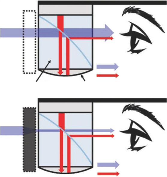
Wang et al. Light: Science & Applications (2021)10:33                                                                    Page 6 of 14

        fabricated by electrochemical copolymerization of 3-                  potential of the working electrode increases when a
        methylthiophene and selenophene under different feed                  certain voltage is applied to the device electrodes55,58
        ratios. Furthermore, their OM in colored states was                   (Fig. 3e, f). As a consequence, the ECD including the
        highly dependent on the monomer feed ratios of                        TNP layer shows satisfactory performance with low
        selenophene/3-methylthiophene. The known                              overvoltage, long-term bistability, and electrochemical
        common rule is that the greater the content of                        cyclability (Fig. 3g). The above method improves the
        selenophene is, the more the optical storage                          bistability of the ECD to a certain degree, because the
        performance is improved. In contrast, the color                       TNPs can effectively stabilize the counter ions they
        will be better in the visible region with an increase                 carry, thus avoiding the reverse EC redox reaction
        in the 3-methylthiophene amount. The best result                      caused by charge combination. However, the
        is usually achieved by compromising to find a                          performance, including the color variation, color
        balanced ratio to achieve a more satisfactory                         conversion speed, and bistability, is still far from
        overall performance. Such property optimization                       satisfactory for electronic displays. There is an urgent
        usually takes considerable time to obtain a better                    need to deeply understand the problems and how to
        overall result. Nevertheless, the comprehensive                       achieve the ideal performance.
        performance is still not satisfactory for electronic           Organic–metallic hybrid polymers are formed by com-
        displays. At the same time, the toxicity of organic         plexing metal ions with organic ligands or polymers with
        Se has always been a controversial issue, which has         coordination sites. Hybrid polymers composed of bis
        hindered its use and development.                           (terpyridine)s and metal ions, such as Fe(II) or Ru(II),
  (c)   By adjusting the size/amount/structure/properties of        show specific colors based on metal-to-ligand charge
        the electrolyte and electroactive material in the ion       transfer absorption59. Benefiting from metal-centered
        storage layer, the device bistability can also be           stability and reversible redox chemistry, organometallic
        enhanced within a certain range55–57. The classic           hybrid polymers show superior long-term stability com-
        solid (or semisolid) ECD structure is as follows: ITO       pared to other conjugated EC polymers60. Van der Boom
        electrode/EC layer/conducting layer/ion storage             and coworkers60–63 have greatly accelerated the develop-
        layer/ITO electrode. The electrolyte involved in all        ment of the field. Historically, by changing the metal types
        three interlayers between the electrodes enhances the       or ligands modified with different substituents, versatile
        electron/charge transfer (conductivity). In addition,       color-to-colorless and color-to-color transitions have
        the electroactive materials in the ion storage layer        been demonstrated. To date, significant efforts have been
        have a vital role in balancing the charge of the EC         devoted to the effective production of related high-quality
        system. Owing to the lower HOMO level of PR-Br              coatings and to improving their EC performance (such as
        (Fig. 3b), the PR-Br-based ECD is capable of                coloring efficiency). It was also hoped that a uniform
        maintaining comparatively good bistable states with         network with high chromophore density could be formed
        an electrolyte of ionic liquids (initial unbleached state   by adjusting the growth process of the relevant EC com-
        for several months/bleached state for 1.8 h). However,      ponents (Fig. 3h). Obviously, how to optimize the bist-
        due to the lack of electroactive material in the ion        ability and the future development of more related
        storage layer near the blank ITO electrode, it is not       materials is worth looking forward to.
        possible to effectively generate enough counter ions to        Despite the advantages of best-in-class power efficiency
        balance the charges in the system, so the device            and user-friendly color mode, the market’s adoption of
        operating voltage (2.8 V) is still relatively high50.       reflective electronic display technologies has been very
        Moreover, in the V-Off state, the electrochemical           slow. This is because the color obtained by these systems
        double layer (EDL) near both sides of the electrode         is still poor, the color conversion speed is not fast enough,
        spontaneously produces inevitable thermodynamic             the color purity is limited and the chemical stability of
        ion diffusion to reduce the internal electric field and      current materials and devices is not ideal; the “bistable”
        the EC colored/uncolored state cannot be maintained         performance is especially not satisfactory. These intract-
        for a long enough time (Fig. 3d). The stability of the      able deficiencies have severely restricted their further
        EDL is highly dependent on the size and                     development and application for cutting-edge digital
        stereochemical structure of the electrolyte ions. By        displays. In fact, these issues are highly related to the
        selecting the appropriate ionic liquid electrolyte, a       traditional EC mechanism (a direct-redox-color-changing
        stable ion pair can be formed between the                   system), intrinsic structures and fully activated local
        electroactive ions and counter ions to avoid the            thermal and electron movement disturbances in the local
        imbalance of ions on both sides and the related             molecular structure. Significant breakthroughs in struc-
        electrostatic repulsion. Meanwhile, by utilizing a TiO2     tural modification or new syntheses for ideal needs have
        nanoparticle (TNP) layer as the ion storage layer, the      been complicated and very difficult to achieve thus far.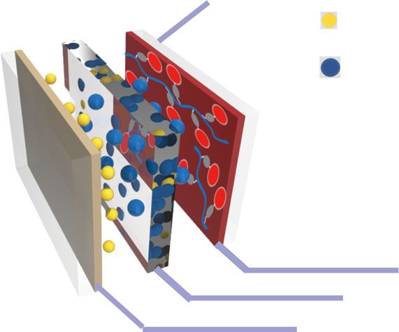
Wang et al. Light: Science & Applications (2021)10:33                                                          Page 7 of 14

Thus, there is an urgent need to develop a new method to       absorbance in the leuco dye color state over the entire
perfect EC properties and extend their application to ideal    visible region, fluoran derivatives (6’-(diethylamino)-2’-
displays via a simple chemical approach.                       [[3-(tri-fluoromethyl)phenyl]amino]-spiro[isobenzofuran-
                                                               1(3H),9’-[9H]xanthene]-3-one) were chosen as molecular
New EC technology overcoming the drawbacks of                  color switches, because their ring-open state has very
traditional electronic displays                                good light absorption capacity in the visible region.
   From the above pioneering works, designing a photo-         DMHQ was utilized as the electro-acid here. Hydro-
nic system possessing ideal color changes and a stabi-         quinone accommodates the lactone ring-opening/closing
lized molecular state is the key to ideal power-saving         reaction of the fluoran dye through proton transfer under
bistable displays. To meet the above challenges, Zhang         electric stimulation. A demo device of an EC optical
et al.64–67 proposed an indirect EC system with a new          shutter (ECOS) was designed and demonstrated by uti-
mechanism—“regulatable          electro-acid/base”-induced     lizing a fluoran dye, as well as a hydroquinone derivative.
reversible molecular color switches, overcoming the            It shows outstanding performance with a very high
insurmountable technical bottleneck of traditional direct      transmittance in its bleached state (82.8% at 550 nm), a
EC systems. Notably, in their indirect EC system, the          low transmittance in its colored state (0.1% at 550 nm), a
coloration units are independent of redox active units,        response time of 1.4 s, and excellent operational stabi-
while these subunits specifically interact with hydrogen-       lity71. An augmented reality display system comprising
bonding groups, mimicking the enzyme reaction centers.         the ECOS was also fabricated by the authors, which
In addition, these systems utilize the mechanism of            exhibits significantly improved visibility of the displayed
intra/intermolecular PCET in the natural photosynthesis        image even under strong ambient light conditions due to
process68,69 (Fig. 4a), which avoids unstable free radicals    the excellent visible-light-absorbing function of the ECOS
during the reaction via collaborative interactions/stabi-      (Fig. 4e, f).
lization and has been widely used to overcome unde-               A very promising device of an indirect EC polymer
sirable energy barriers for various chemical reactions and     system was recently demonstrated. It is designed by first
design functional molecules. Through delicate design of        combining the benzoate-lactone-containing fluoran sub-
biomimetic molecular switches and supramolecular               unit and the p-phenylenediamine moiety to make the
condensed systems, the redox performance of the                desired molecule and then grafting them onto methyl-
molecular “reaction center” and reversibility of color         methacrylate polymer chains by an oxyethyl linkage. This
switching were greatly promoted by dynamic self-               new system improves the film-forming properties of its
regulation and charge redistribution of local micro-           polymer composites by imitating the interwoven structure
structures. Most importantly, this design avoided the          of peptides69. Compared with conventional direct EC
problems of unstable redox states (high entropy energy         materials, the comprehensive performance of this system
states) of conventional EC pathways. Thus, it greatly          based on a concerted intramolecular PCET mechanism
improved the bistability, coloration efficiency, utilization    demonstrates overwhelming superiority. The key perfor-
efficiency of external light and electrical energy, and         mance of its related materials is close to (or even exceeds)
chemical stability of materials and devices (Fig. 4b).         the optimum performance of existing EC materials.
Furthermore, through a simplified device assembly pro-          Impressively, a clear and stable display for more than two
cess, rapid and reversible color changes in the dynamic        days without any refreshing or power consumption is
state and stable performance in the static state of bio-       realized. More importantly, this display is similar to a
mimetic molecular systems in ECDs under electric field          paper book and suitable for reading in bright sunlight.
induction were realized (Fig. 4c, d).                          The simplified production/assembly process will also
   To broaden the use of this new indirect EC system,          contribute to future industrialization and marketization
Kwon and coworkers70 demonstrated a full-color reflec-          (Fig. 4d). The above exciting advancements in EC mate-
tive display consisting of different color production units    rials and technology will surely inspire and greatly boost
selected as an indirect EC system. Here, to show red, blue,    the further development of green technology in electronic
green, and black colors, different leuco dyes were utilized.   displays.
2,3-Dimethylhydroquinone (DMHQ), as the redox active
species and proton donor compound, could reversibly            Challenges and future directions for green display
induce the bleached or colored states of the leuco dye,        technologies
which was determined by the reaction of the leuco dye            Although the new green technologies of bistable displays
with acid species. The novel ECD fabricated with the           have demonstrated super-power-saving performance, they
indirect EC system can easily provide various colors with      are mostly competing for low-end markets at present. As the
high brightness and saturation with a broad grayscale. To      market share is not large enough, these green technologies
achieve high transparency in the bleached state and large      have not yet received widespread attention. The reason is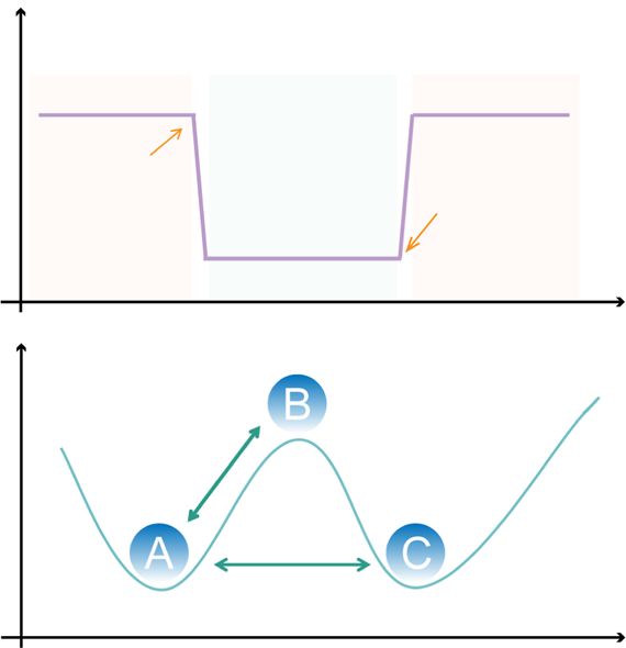
Wang et al. Light: Science & Applications (2021)10:33 Page 8 of 14
a H O H O b 60
N N N N N
O O N
–2e–
Black color display
O O 50
+2e–
Optical memory time (h)
N N
40
Multicolor display
C
H+ transfer
on
H+ transfer
Blue color display
30
ce
Blue color display
Blue color display
Blue color display
Blue color display
rte
Multicolor display
d
PC
ET
20
HO
N
HO
N 10
N N N N
O O
+2e–
O O
–2e– 0
Ref 50 Ref 55 Ref 56 Ref 36 Ref 31 Ref 42 Ref 68 Ref 69
N N Conjugated Inorganic PCET
polymer material material
c d e OST-HMD
ITO
+ Micro OLED
TBA
E C D off (bleached)
PF6–
Ambient light
RHMA
Display light
Beam splitter Mirror
Micro OLED
Electrochromic layer 2
E C D on (colored)
V
da
.0
ys
V
+1
Conducting layer
.8
–0
Ion storage layer
–0.8 V
Ambient light
f Display light
ECD off ECD on ECD off ECD on ECD off ECD on ECD off ECD on
Fig. 4 Unconventional design strategies to promote the development of the bistable electrochromic material/device field. a EC mechanism
based on intramolecular proton-coupled electron transfer69. b Bistable performance of different types of EC technology. c Structure of a bistable EC
device. TBA+, tetrabutyl ammonium ion; RHMA, EC polymer containing the benzoate-lactone-containing fluoran subunit and the p-phenylenediamine
moiety69. d Promising applications of bistable EC devices in energy-saving displays—multicolor electronic label shelf and billboard68,69. e Mechanism of
an ECD regulating the ambient light contrast ratio in an AR system71. (f) Color gamut and display images of the AR system with the ECD off and on
according to different ambient lighting conditions in an office (400 lx), in shade (5000 lx), on a cloudy day (10000 lx), and on a sunny day (15 000 lx)71
that parts of their performance (such as the speed of turning display to enable it to meet the actual requirements of
pages and the color quality/brightness) are not yet com- high-end displays as soon as possible, i.e., to make its key
parable to those of mainstream light-emitting electronic properties, such as the display switching speed, color
display products. Thus, there are two approaches to enable contrast, cycling times, and chemical stability, fully com-
the long-awaited green electronic displays that still meet parable to those of the existing electronic displays.
human needs while using energy efficiently to quickly However, as mentioned above, there are many very diffi-
become widespread in the mainstream market. cult technical obstacles in this path.
One possible solution is to optimize the comprehensive First, in terms of molecular design, overcoming the
performance of the bistable light-absorbing electronic oxidative degradation and photobleaching problems ofWang et al. Light: Science & Applications (2021)10:33 Page 9 of 14 known acid–base dyes is always a challenge72. As photo- comprehensive performance still needs to be further bleaching/oxidative degradation is highly correlated with improved, to expand their practical applications. First, UV and oxygen (O2) exposure, it can possibly be solved by strategies and materials for achieving more universal pan- exploring better sealing and packaging materials to avoid chromatic tunability remain to be further developed, O2 and UV damage. A disadvantage here is that the initial especially for the change from colorless to colorful investment in the production plant and equipment will be (“on–off” display mode). Second, although practical very expensive, and the oxygen barrier performance methods, such as electrodeposition and sol-gel techniques, requirements of the sealing and packaging materials are have been exploited/developed, there is still a need for also very demanding. Achieving the same goal with low further research on large-area and low-cost uniform film cost and high efficiency is a major challenge in this field. preparation technology. Third, it is necessary to further Obviously, we need to go beyond the traditional thinking improve the electron/ion transfer rate by introducing and technical frameworks. Regarding the protection of nanomaterials into the electrode and EC layer to overcome dye molecules from UV light, in addition to using tradi- the bottleneck that the response rate of current ECDs tional packaging materials to absorb and block light, we cannot display information satisfactorily. can explore whether UV light can be effectively converted The third problem is that the EC reaction mechanism into visible light by using small molecules or oligomers in and kinetics are still not clear enough. The influence of the EC layer or packaging materials, i.e., whether the color the system microenvironment on the EC reaction, such as brightness of EC displays can be enhanced via energy the types of solvents, electrolytes, and additives, tem- downconversion. Furthermore, we can explore increasing perature and pH, needs to be further characterized and the visible light intensity by energy upconversion to fully observed via various in situ tests. The synergism in the utilize the waste energy from heat dissipation of sunlight PCET reaction, the dynamic processes of the electrons or in the environment. and ions in the inorganic/organic EC reaction, the elec- The second problem is the limited options for color- tron transfer between the electrodes and materials, and changing molecules with different colors and good che- other processes involved in the EC reaction, all need to be mical stability, which is highly related to traditional direct understood more deeply and optimized accurately and EC systems. For years, researchers have been devoted to intelligently. the design and synthesis of complex new materials with The fourth problem is highly related to device assembly. direct oxidation–reduction discoloration by modifying Compared with LCDs/OLEDs, the color of current EC related substituents and structures to improve the prop- displays is not bright enough and their page-turning speed erties and overcome the above shortcomings, but the is slow. The main reason is that the contact area between progress is not satisfactory73. Unlike the traditional che- the flat electrode and the EC molecules is limited. Current mical approach, the aforementioned insurmountable pro- EC systems utilize electrolytes as charge carriers for redox blems could be greatly overcome by indirect EC systems. of color-changing molecules. The diffusion rate of known This new strategy can effectively use hundreds of known electrolytes is not fast enough, especially in solid EC thin molecules as indirect EC colorants, which are easily avail- films. The color brightness of EC displays is highly related able, and can be highly economical by selecting desirable to the amount of color-changing molecules (or subunits colorants with high molar absorption coefficients. In of redox polymers), which is highly related to the thick- addition to achieving ideal color changes by the “reversible ness of the EC thin film. In contrast, the page-turning electro-acid/base” method, we can also explore other speed of EC displays is inversely related to the device methods of multicomponent collaborative interaction. For thickness69. Even though new electrolytes for better example, additional molecules/oligomers/nanoparticles/ charge transfer have been a long-awaited dream, success quantum dots with color/emission up/downconversion or has been very limited thus far. As the size of electrolytes sharpening characteristics can be used to improve the color cannot be small enough, the weak intermolecular inter- purity, quality and brightness of traditional EC/OLED action between the known electrolytes and media greatly materials. Furthermore, the use of traditional direct EC/ slows the diffusion rate and charge transfer speed. Thus, electroluminescent and emerging indirect EC or electro- significantly increasing the contact area between the fluorochromic systems in the same ECD is also worth electrode and EC molecules, as well as the electron and exploring. It is possible to obtain complementary advan- charge transfer efficiency in solid or semisolid films, is an tages and avoid the shortcomings in this way. In addition, extremely important future research direction. The tra- the addition/intercalation of free radical quenchers or ditional planar ITO structure needs to be replaced by a stabilizers and the avoidance of oxygen ingress can improve new type of electrode that has a highly conductive three- the chemical stability of traditional EC materials. Although dimensional (3D) structure and excellent transparency. inorganic materials exhibit outstanding chemical stability How to long-term stably and tightly connect EC materials and significant progress has been achieved recently, the to the electrode surface through chemical or physical
Wang et al. Light: Science & Applications (2021)10:33                                                           Page 10 of 14

methods is also a subject worth exploring. At the same          revolutionize modem mainstream electronic displays,
time, the ability to form a protective layer with switchable    energy storage, and other technologies, and overcome the
ion/electron channels on the surface of the EC material         long-puzzled technical bottleneck of electrolyte diffusion.
can not only ensure the smooth transmission of ions or          Meanwhile, the development and combination of more
electrons during the EC process but also effectively pre-       advanced in situ spectroscopy techniques, such as in situ
vent self-fading or self-discharge when there is no             electron microscopy and in situ nuclear magnetic reso-
electric field.                                                  nance, to deepen the understanding of state changes of
  The primary goals are further improvement of device           structures during the reaction process will also contribute
fabrication technologies, and further development and           to the precise design of bistable EC materials.
utilization of needed auxiliary materials. In addition, the       The other possible solution is to revolutionize the
compatibility of the above new materials and technologies       mainstream light-emitting display technologies and make
with mainstream display technology is the key to their          them partially (or fully) bistable and super-power saving.
rapid market entry, and the integration of old and new          To realize this seemingly “impossible” dream, revolu-
display technologies is a future direction. In particular, we   tionary technologies combined with new mechanism
need to explore whether we can use known/new electron           design and device structure optimization are clearly nee-
and hole carriers in OLEDs to speed up the EC speed. We         ded. We should explore whether we can delay their light
should explore speeding up of the diffusion rate of elec-       emission or extend the lighting time with limited elec-
trolytes via media modification to increase the micro/           trical stimulation via new materials and unusual device
nanoporosity of EC thin films via known technologies of          structure designs. For example, we can use existing
new structural design and molecular 3D self-assembly,           known mechanisms, such as Förster resonance energy
metal-organic frameworks, freeze-drying, hydrogels, etc.        transfer75, photoelectron transfer, aggregation-induced
We should also explore significantly increasing the contact      luminescence76, phosphorescence fluorescence rever-
area between the electrode and EC molecules via realiza-        sal77, and PCET, to effectively delay and extend the light
tion of nanorange 3D electrode networks via laser etching,      emission time. Important progress has also been made in
3D printing, self-assembly, thermal healing, electrospin-       related fields, such as long-persistent luminescence (LPL)
ning, etc. It is worth mentioning that the advantages of        materials with the ability to store and slowly release
nanomaterials, such as nanowires, nanorods, nanobelts,          excited-state energy78. In addition to improving the effi-
nanofibers, and nanoparticles, include a large electrolyte       ciency of exciting triplet states, it is equally important to
and electrode contact area, high electrical conductivity, a     protect triplet states to prolong their luminescence life-
short ion diffusion route in the diameter direction, and        time. Through the use of inorganic/organic crystals,
efficient electron transport in the length direction. As the     quantum dots, metal-organic frameworks, H-aggregates,
ion/electron double injection distance can be significantly      functionalized/hybridized/defective small/large con-
reduced in this way, the switch response speed will be          densed ring conjugated molecular systems, and others,
improved to achieve satisfactory results. Nevertheless, the     significant progress has been made in related research in
size, dimensionality, shape, and structure of these nano-       this area to date. Recently, an organic LPL long-acting
materials should be delicately designed and controlled. On      luminescent material was fabricated by using triphenyl
the one hand, the specific surface area and porosity of the      quaternary ammonium phosphorus TPP-3C2B as an
materials should be improved by fabricating nanos-              organic electron trap. The cationic triphenylphosphonium
tructures. On the other hand, due to the high density and       core acts as a strong electron acceptor for the photo-
small pore size of some nanomaterials, the important cri-       induced charge transfer event and can also serve as a
terion for selecting and using them is to determine whether     protective trap to stabilize and protect the excited free
they hinder ion migration. As nerve systems in nature likely    radicals so that the system can slowly reorganize with
use the stimulus response collaborative actions of dynamic      long-lasting luminescence characteristics, with a lumi-
alteration of their 3D structures and ionization to transfer    nescence duration of up to 7 h. In addition, we can also
electrons and charges, their use would be a very mild and       adopt strategies involving cross-fusion with existing
instant strategy that effectively avoids steric hindrance and   technologies, such as electrofluorescence, electropho-
heat loss during electrolyte diffusion in known EC, battery,    sphorescence, controllable delayed (or long-lived) elec-
capacitor, and other electrical systems. Thus, we should        troluminescence, and indirect EC molecular switching.
learn in depth from nature, explore the possibility of man-     We can attempt to explore whether to convert current
made “nerve networks” systems74 via structural design,          direct LEDs/OLEDs into indirect LEDs/OLEDs, EC-
synthesis, and molecular self-assembly, and attempt to use      LEDs/OLEDs, etc. Apart from saving energy by exploring
bionic “nerve networks” to replace the current method of        the device bistability, increasing their luminous efficiency
electrolyte diffusion for quick transfer of electrons and       is an alternative method to save energy. To date, the
charges in the system. The success of this will likely          luminous efficiency of LEDs/OLEDs is very low, mainly
Wang et al. Light: Science & Applications (2021)10:33                                                                     Page 11 of 14

due to their internal resistance and heat dissipation. Thus,         are not only crucial for the future of intelligent life but
altering the display modes of LEDs/OLEDs or coupling                 also can drive the related high-tech industry.
metal/nonmetal (i.e., graphene, carbon nanotube, carbon                 Despite the heavy responsibilities, we foresee a bright
60/70/80, conducting polymer, etc.) conductors or bionic             future. We are convinced that future super-power-saving
electronic 3D “nerve networks” to the systems might be               bistable displays will not only belong to the field of known
good alternatives to effectively reduce the internal resis-          EC and electrophoresis technologies but also appear in the
tance and heat dissipation and increase the luminous                 field of electroluminescence and others. History shows that
efficiency. Moreover, the role of supramolecular weak                 the driving force behind scientific and social progress is the
bonds, such as hydrogen bonds, in material design and                spirit of doubt and challenge. Many seemingly difficult
structural stability cannot be ignored. The integration of           problems are gradually resolved by further understanding
various known or new display techniques will likely offer a          the cause of the problem through the collaboration of sci-
promising strategy to satisfy various human needs, such as           ence and technology workers. Countless facts exemplify that
EC-LED/OLED dual mode systems for all-weather ultra-                 many dreams in the world are no longer impossible, but
power-saving display technology.                                     people do not dare think about or are not willing to put
  In addition to traditional EC windows, bistable display            effort into achieving them. Essentially, traditional thinking
technology involving electrochromism is gradually being              and restriction of cognitive abilities hinder people’s inven-
applied in energy-saving electronic price tags, billboards,          tiveness and creativity. Once the restraint of thinking that
rearview mirrors, and artificial irises to adjust the camera          certain achievements are “impossible” is broken, various
aperture. By preparing reflective ECDs, we can exploit                miracles will continue to be realized by humans via magi-
electronic paper products with multicolor displays and               cally “possible” explorations. Hopefully, in the near future,
repeatable erasure, which can greatly save energy and                we can overcome the above bottlenecks through coopera-
avoid waste and consumption of paper. Apart from ser-                tion with an increasing number of visionary researchers and
ving people’s daily life needs, novel electronic materials           industry to optimize the green technologies of bistable dis-
have wide cutting-edge applications, such as in the field of          plays and promote their global commercialization (Fig. 5).
molecular computers with information storage capability.
Combined with flexible substrates, such as fibers and                  Opportunities and prospects for a green
polymers, the bistable electronic materials with full-color          technology revolution
adjustable properties are promising in active and con-                 Finally, we would like to note that the aforementioned
trollable military camouflage. ECDs with transparent                  problems regarding electronic displays and possible
display performance have great potential in the fields of             solutions epitomize the rapid development of modern
augmented visual reality, head-up display and artificial              society. The problems of very high power consumption
intelligence. Overall, bistable electronic display products          and low energy utilization efficiency widely occur in all

                                                    Power off             Power up
                              Power up                                                          Power off

 Fig. 5 Research strategy and development of green technologies in the future. Scheme of the green display technologies combined with
 untraditional strategies
Wang et al. Light: Science & Applications (2021)10:33 Page 12 of 14
human activities, such as those involving air conditioners, understand the above scientific and technological chal-
refrigerators, electric cars, computer networks, and lenges and their significance, trigger global cooperation to
automation control systems. For instance, the current challenge the “impossible” scientifically forbidden zone,
power consumption of global lighting is 20% of global and bring innovation in green technology to a new level.
electricity generation. Meanwhile, the electro-optical
Author details
conversion efficiency of lamps is extremely low, only 1
State Key Laboratory of Supramolecular Structure and Materials, College of
5–20% of the theoretical conversion rate, with the vast Chemistry, Jilin University, Changchun 130012, China. 2Department of
majority wasted via heat dissipation. We must perform in- Chemistry and Biochemistry, University of California, Santa Barbara, Santa
Barbara, California 93106, USA. 3State Grid Heilongjiang Electric Power Co., Ltd,
depth studies to find the root cause of the high resource Heihe Power Supply Company, Heihe 164300, China. 4Jiaxing IrS Display
consumption and low energy utilization efficiency and Technology Co., Ltd, Jiashan 314113, China
improve this situation by changing the existing mode of
technology development. In this spirit, a few examples are Author contributions
S.X.-A.Z., Y.W., and H.N. conceived of and drafted the paper. S.X.-A.Z., Y.-M.Z., J.
presented as follows: (i) we could mimic the light pro- H., and Y.A. contributed formative ideas, recommendations, and assisted with
duction of fireflies to achieve highly efficient chemilumi- editing the paper. This work was supported by the National Natural Science
nescence. The energy conversion efficiency of lighting is Foundation under Grant numbers 22075098 and 21875087.
currently extremely low in the multiprocess of chemical Conflict of interest
energy→heat→mechanical force→electricity→light. We The authors declare that they have no conflict of interest.
could increase the energy conversion efficiency sig-
nificantly if we can find a better method to generate light
from chemical energy (or heat) directly and efficiently. Received: 24 July 2020 Revised: 2 December 2020 Accepted: 14 December
2020
The known chemiluminescence seems to involve a func-
tionalized aromatic structure, which likely acts as a rela-
tively rigid energy transfer center to assist electron
transfer and light emission and reduce heat loss. We References
should learn from nature and explore the possibility of 1. Chen, H. W. et al. Liquid crystal display and organic light-emitting diode
display: present status and future perspectives. Light. Sci. Appl. 7, 17168 (2018).
increasing the light-emitting efficiency by introducing 2. Grätzel, M. Materials science: ultrafast colour displays. Nature 409, 575–576
partially functionalized aromatic derivatives into the (2001).
lighting systems of LEDs, OLEDs, thermo-lighting, chemi- 3. Oh, S. W. et al. Encapsulated-dye all-organic charged colored ink nanoparticles
for electrophoretic image display. Adv. Mater. 21, 4987–4991 (2009).
lighting, etc. Hopefully, similar to the firefly, we could 4. Kikuchi, H. et al. Polymer-stabilized liquid crystal blue phases. Nat. Mater. 1,
generate light at low temperatures and create a “miniature 64–68 (2002).
sun” via the effective use of geothermal radiation, the heat 5. Comiskey, B. et al. An electrophoretic ink for all-printed reflective electronic
displays. Nature 394, 253–255 (1998).
lost from fossil fuel power plants, etc. In addition, we 6. Graham-Rowe, D. Electronic paper rewrites the rulebook for displays. Nat.
could create an effective low-temperature thermo-light- Photonics 1, 248–251 (2007).
ning system to utilize heat radiation in nature via two- 7. Hayes, R. A. & Feenstra, B. J. Video-speed electronic paper based on electro-
wetting. Nature 425, 383–385 (2003).
photon/multiphoton integration and blueshifted light 8. Kim, D. Y. & Steckl, A. J. Electrowetting on paper for electronic paper display.
conversion with the help of bionic aromatic platform ACS Appl. Mater. Interfaces 2, 3318–3323 (2010).
carriers. (ii) We could use the synergy of the resonance 9. Beaujuge, P. M. & Reynolds, J. R. Color control in π-conjugated organic
polymers for use in electrochromic devices. Chem. Rev. 110, 268
field effect and/or quantum resonance wave effect of high- (2010).
quality LEDs/OLEDs, optical fibers, laser systems, or 10. Cai, G. F. et al. Molecular level assembly for high-performance flexible elec-
others to achieve light delivery without (or with low) trochromic energy-storage devices. ACS Energy Lett. 5, 1159–1166 (2020).
11. Kortz, C. et al. Complementary hybrid electrodes for high contrast electro-
energy loss. (iii) We could use super-power-saving EC chromic devices with fast response. Nat. Commun. 10, 4874 (2019).
materials as indoor/outdoor decorations and smart win- 12. Zhang, W. R. et al. A single-pixel RGB device in a colorful alphanumeric
dows that are capable of energy storage and release or electrofluorochromic display. Adv. Mater. 32, 2003121 (2020).
13. Wang, Z. et al. Towards full-colour tunability of inorganic electrochromic
power generators/battery chargers. devices using ultracompact fabry-perot nanocavities. Nat. Commun. 11, 302
As long as we are actively learning from nature, advan- (2020).
cing the understanding of its working principles in depth, 14. Kholghi Eshkalak, S. et al. Overview of electronic ink and methods of pro-
duction for use in electronic displays. Opt. Laser Technol. 117, 38–51 (2019).
applying what we newly learned, and questioning and 15. Huh, J. W. et al. Bistable light shutter using dye-doped cholesteric liquid
challenging traditional knowledge, we will become “mas- crystals driven with crossed patterned electrodes. J. Disp. Technol. 12, 779–783
ters of creating miracles” and make many seemingly (2016).
16. Li, J. et al. Ionic-surfactant-mediated electro-dewetting for digital microfluidics.
“impossible” achievements “possible”. With the new gen- Nature 572, 507–510 (2019).
eration of EC or EC-LED/OLED materials and technolo- 17. Li, H. Z., Firby, C. J. & Elezzabi, A. Y. Rechargeable aqueous hybrid Zn2+/Al3+
gies, in the near future, the glamour of electronic display electrochromic batteries. Joule 3, 2268–2278 (2019).
18. Li, H. Z. & Elezzabi, A. Y. Simultaneously enabling dynamic transparency control
use will no longer entail environmental issues. Hopefully, and electrical energy storage via electrochromism. Nanoscale Horiz. 5, 691–695
this study can allow an increasing number of researchers to (2020).You can also read