AdderLink Infinity 100T - User Guide - KVM Extension - AWS
←
→
Page content transcription
If your browser does not render page correctly, please read the page content below
AdderLink™ Infinity 100T
                       User Guide

       Experts in   KVM Extension
     Connectivity
        Solutions   Solutions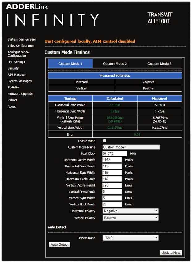
Contents
Introduction                                                                                                                 Operation

                                                                                                                                                                                                                                                             INSTALLATION
 Welcome.................................................................................................................2    Status indicators..................................................................................................11
 Supplied items........................................................................................................3      Resetting...............................................................................................................11
 Optional extras......................................................................................................3
                                                                                                                             Further information
Installation                                                                                                                  Getting assistance...............................................................................................12
 Connections...........................................................................................................4      Appendix A - Supported video modes...........................................................13

                                                                                                                                                                                                                                                             CONFIGURATION
   Video link..........................................................................................................5      Appendix B - Configuration pages..................................................................14
   Network link....................................................................................................6          Appendix C - Dimensions.................................................................................25
   USB and power connections........................................................................7                         Appendix D - Tips for success when networking ALIF units....................26
                                                                                                                              Appendix E - Troubleshooting..........................................................................28
Configuration                                                                                                                 Appendix F - Glossary.......................................................................................30
 Initial configuration...............................................................................................8        Appendix G - Open source licenses...............................................................33
     Manual factory reset.......................................................................................8

                                                                                                                                                                                                                                                             OPERATION
     AdderLink Infinity browser-based configuration utility..........................9                                       Index
 Restoring a backup firmware image................................................................10
 Performing an upgrade.......................................................................................10

                                                                                                                                                                                                                                                           INFORMATION
                                                                                                                                                                                                                                                              FURTHER
                                                                                                                                                                                                                                                             INDEX
                                                                                                                                                                                                                                                             1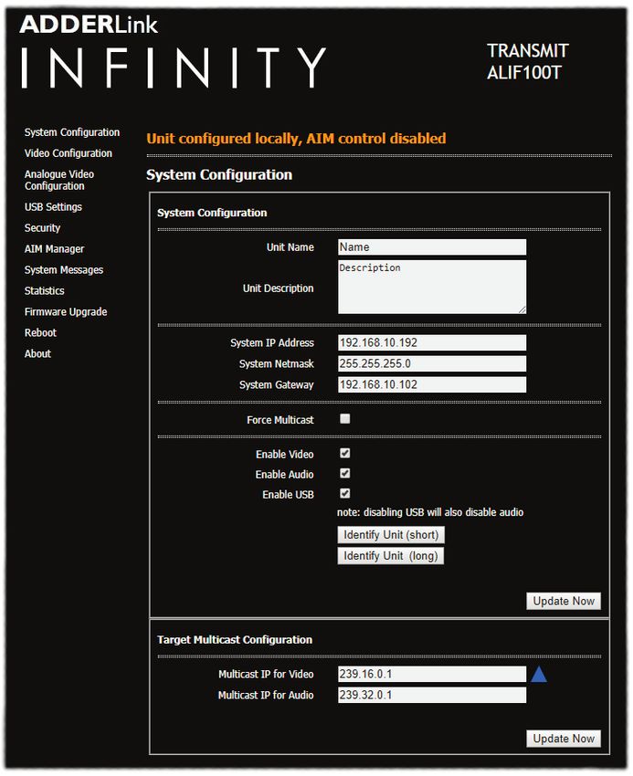
Introduction
WELCOME                                                                                                  ALIF and A.I.M.
Thank you for choosing the AdderLink™ Infinity (aka ALIF) family of high capacity digital                Where multiple ALIF units are used on a network, we have developed the AdderLink

                                                                                                                                                                                                       INSTALLATION
extenders/switches. By encoding high quality video, digital audio and USB data into                      Infinity Management (A.I.M.) server to allow comprehensive and secure central
Internet Protocol (IP) messages, ALIF units offer flexible ways to link peripherals and                  control of all transmitters, receivers and users.
systems via standard networks.
This guide covers the ALIF100T unit, a highly compact dongle which can be attached to
its host computer and transfer high quality video (single link DVI, DisplayPort™ or VGA -
according to the chosen model) and USB signals across your network.

                                                                                                                                                                                                       CONFIGURATION
One-to-one configuration
                                                                                                         When using an A.I.M. server to configure ALIF units, it is vital that all ALIF units that
The simplest configuration links one RX unit to a single TX unit, either by a direct link or over much   you wish to locate and control are set to their factory default settings. Otherwise
greater distances via a high speed network.                                                              they will not be located by the A.I.M. server. If necessary, perform a factory reset on
                                                                                                         each ALIF unit.
                                                                                                         Notes:
          ALIF100T                                                         ALIF RX
                                                                                                         • If you are using one or more ALIF100T transmitters within an installation managed by an
                                                                                                           A.I.M. server, the A.I.M. server must be running firmware version 4.7 or above.
                                                                                                         • If you are using the VGA equipped variant of ALIF100T, then the A.I.M. server must be

                                                                                                                                                                                                       OPERATION
                                                                                                           running firmware version 4.8 or above.

One-to-many configuration
Using multicast techniques, an unlimited number                                                          Please also see Appendix D - Tips for success when networking ALIF units
of receivers* can receive video and audio data                             ALIF RX
streams from a single TX unit.

                                                                                                                                                                                                     INFORMATION
                                                                                                                                                                                                        FURTHER
                                         Gigabit
          ALIF100T                                                         ALIF RX
                                        Ethernet

* A maximum of thirteen concurrent USB inputs (via
                                                                           ALIF RX
multiple RX units) are permitted to a single TX unit.

                                                                                                                                                                                                       INDEX
                                                                                                                                                                                                       2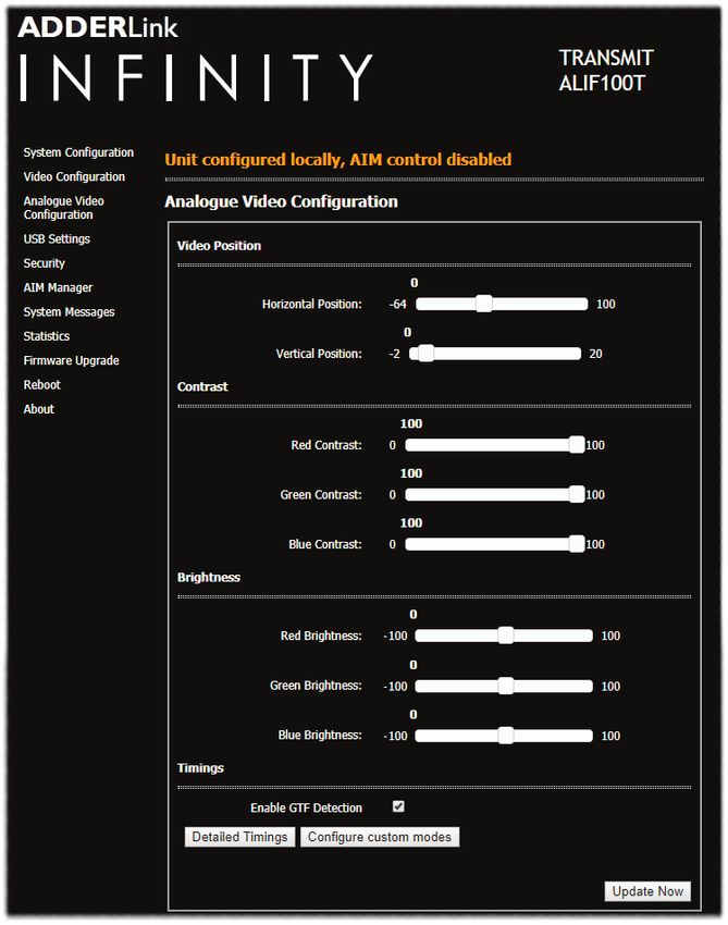
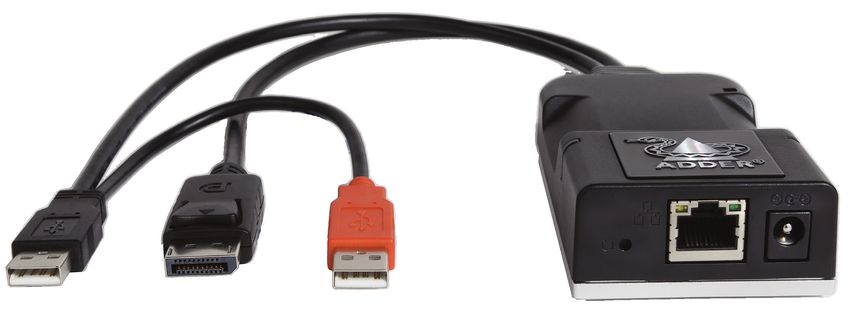
SUPPLIED ITEMS                                             OPTIONAL EXTRAS

                                                                                                                               INSTALLATION
                                       ALIF100T-DVI unit

                                                            12.5W power adapter
                                                            Part number: PSU-IEC-5VDC-2.5A

                                                                                                                               CONFIGURATION
                                                                                              Country-specific power cords
                                                                                              CAB-IEC-AUS (Australia)
                                                                                             CAB-IEC-EURO (Europe)
                                                                                               CAB-IEC-UK (United Kingdom)
                                                                                              CAB-IEC-USA (United States)

                                       ALIF100T-DP unit

                                                                                                                               OPERATION
                                                                                                                             INFORMATION
                                                                                                                                FURTHER
                                       ALIF100T-VGA unit

          Information wallet

                                                                                                                               INDEX
              containing:
      Four self-adhesive rubber feet
            Quick start guide
            Safety document

                                                                                                                               3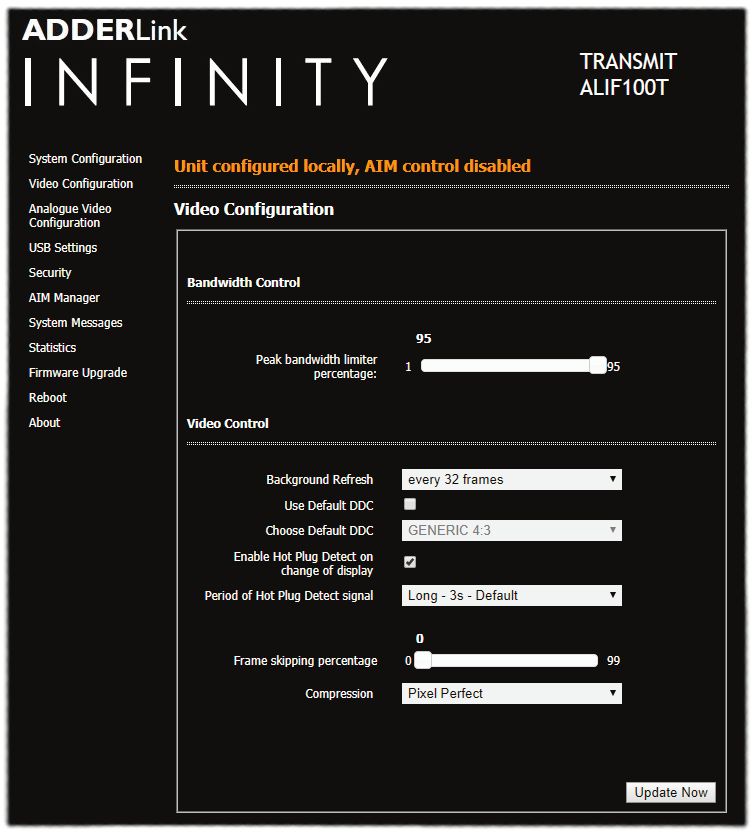
Installation
CONNECTIONS
Installation involves linking the ALIF100T unit to various ports on the

                                                                                                                                                                     INSTALLATION
host computer, while the ALIF RX unit is attached to your peripherals:

                                                                                                                                                                     CONFIGURATION
                                                                                                                                         DisplayPort
                                                                           Cable tie
                                                                          mounting slot
                                                                                                                                             or

                                                                                      Status                                                           Connector
                                                                                   indicators                                              DVI-D         input
                                                                                    (page 11)                                                           (page 5)

                                                                                                                                                                     OPERATION
                                                                                                                                             or

                                                                                                                                            VGA

                                                                                                                                                                   INFORMATION
                                                                                                                           Optional

                                                                                                                                                                      FURTHER
                                                                                                                        external power
                                                                                                                             input
                                                                                                             Ethernet      (page 7)
                                                                                                               port
                                                                                                             (page 6)
                                                                                                   Reset
                                                                                                   button
                                                                                                  (page 8)

                                                                                                                                                                     INDEX
                                                                                Red USB plug provides
                                                                                 power only when the
                                                                               external power adapter is
                                                                                     not present

                                               Black USB plug provides USB
                                                                                       (page 7)
                                             signals (plus power if the external
                                               power adapter is not present)
                                                                                                                                                                     4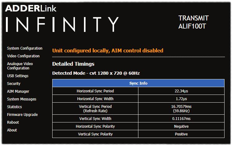
Video link
Each ALIF100T unit is supplied with either a DisplayPort™, DVI-D (single link) or
VGA video connector (model dependant) .Video signals at pixel clocks up to 165MHz
(equivalent to a maximum resolution of 1920 x 1200 at 60Hz) are permissible.

To make a video link

                                                                                                                                     INSTALLATION
1 Connect the ALIF100T video connector to the DisplayPort™, DVI-D or VGA
  socket of the host computer:

   ALIF100T DP model                                                                                                     Host
                                   Host computer
                                                          ALIF100T DVI-D model         Host       ALIF100T VGA model
                                                                                     computer                          computer
                                    DisplayPort                                     DVI-D video                        VGA video
                                     connector                                         port                              port

                                                                                                                                     CONFIGURATION
                                                                                                                                     OPERATION
                                                                                                                                   INFORMATION
                                                                                                                                      FURTHER
                                                                                                                                     INDEX
                                                                                                                                     5
Network link
ALIF transmitters and receivers can either be connected directly to each other or via a
high speed network.
A single Gigabit Ethernet port is located on the front panel. For direct links via Ethernet
cable, the length of cable should not exceed 100 metres (328 feet). Network cables
used for connections may be category 5, 5e, 6 or 7 twisted-pair cable. The ALIF100T
INSTALLATION
unit has an autosensing capability on its network interfaces, so for direct point-to-point
connections, no ‘crossover’ Ethernet cable is required.
To link the ALIF100T unit
1 Connect a CAT 5, 5e, 6, or 7 cable to the Gigabit Ethernet socket on the front panel
of the ALIF100T unit.
CONFIGURATION
OPERATION
CAT 5, 5e, 6, or 7 link
either directly from
the other ALIF unit
or from a Gigabit
Ethernet switch
2 Connect the other end of the cable either directly to an ALIF receiver or to a Gigabit
INFORMATION
Ethernet switch, as appropriate.
FURTHER
3 [For connections via a network] repeat steps 1 and 2 for the other ALIF unit(s).
Please see Appendix D for important tips about networking ALIF units.
INDEX
6USB and power connections
The ALIF100T unit is designed to be as flexible as possible. It can either operate using
Black USB plug provides
an optional external power adapter (see page 3) or derive all of its power from its USB signals (plus power if
two USB plugs. The main advantage offered by using an external power adapter is that it the external power adapter
Host computer
allows the ALIF100T unit to be active before the host computer; thus allowing a remote is not present)
USB ports
user to access the host’s initial boot up and access the BIOS menu, when required.
INSTALLATION
If powered by USB only, then both the black and red USB plugs need to be connected.
If powered by external power adapter, only the black USB plug needs to be connected,
for signal purposes. Whenever, the external power adapter is attached and operating,
then power will be taken from it rather than the USB plugs. There is no problem if the
red USB plug remains connected while the power adapter is used.
This is summarized as follows:
Power Black Red
CONFIGURATION
adapter USB USB Power sourcing behavior
û ü ü Power taken from both USB plugs.
Red USB plug provides
ü ü û Power taken from power adapter only. power only when the
external power adapter is
ü ü ü Power taken from power adapter only, unless it becomes not present
unavailable, in which case power will be taken from both
USB plugs after a short interruption.
OPERATION
Note:The USB plugs do not operate as a seamless failover for the external power adapter; there
will be a short interruption as operation switches from one power source to the other.
INFORMATION
FURTHER
From the optional
external power
INDEX
adapter
7Configuration
INITIAL CONFIGURATION
ALIF units are designed to be as flexible as possible and this principle extends also to Manual factory reset
INSTALLATION
their configuration. A factory reset returns ALIF100T unit to its default configuration.You can perform
factory resets using the AdderLink Infinity browser-based configuration utility or by
Direct linking using this direct manual method.
Where ALIF transmitters and receivers are directly linked to each other, very little To perform a manual factory reset
configuration action is required, provided that they have their factory default settings in 1 Power on the ALIF100T unit.
place. If the standard settings have been changed in a previous installation, you merely
2 Use a narrow implement (e.g. a straightened-out paper clip) to press-and-hold
need to perform a factory reset on each unit.
the recessed reset button on the front panel for roughly fifteen seconds, until the
CONFIGURATION
Networked linking indicators turn blue (Note: alternating red/green indications will occur during the fifteen
Where ALIF units are connected via networked links, you can either configure them second period while the button is still pressed).
individually, or configure them collectively using an A.I.M. server:
• Configuring networked ALIF units individually - You need to specify the
network addresses of the ALIF units so that they can locate each other. This is done
by running the AdderLink Infinity browser-based configuration utility on a computer
system linked to the same network as the ALIF units.
• Configuring ALIF units collectively - The AdderLink Infinity Management
OPERATION
(A.I.M.) server allows you to configure, control and coordinate any number of ALIF
transmitters and receivers from a single application.
• If you are using one or more ALIF100T transmitters within an installation managed by an
A.I.M. server, the A.I.M. server must be running firmware version 4.7 or above.
• If you are using the VGA equipped variant of ALIF100T, then the A.I.M. server must be
Use a straightened-out paper
running firmware version 4.8 or above. clip to press the reset button
INFORMATION
for roughly 5 seconds
IMPORTANT: When using A.I.M. to configure ALIF units, it is vital that all units that
FURTHER
3 Release the reset switch.
you wish to locate and control are set to their factory default settings. Otherwise
they will not be located by the A.I.M. server. If necessary, perform a factory reset on The indicators will remain blue for a short while (less than ten seconds) while
each ALIF unit. ALIF100T unit configures itself and should then change to green if all connections
are correct; or orange if one or more of the video, USB and/or network links are
Please also see Appendix D - Tips for success when networking ALIF units missing.
INDEX
8AdderLink Infinity browser-based configuration utility
The browser-based configuration utility within all TX and RX units requires a network To access the browser-based configuration utility
connection between the ALIF100T unit and a computer on the same network. The 1 Temporarily connect the ALIF100T unit and your computer, as discussed left.
configuration utility allows you to perform many important functions. Please see 2 Run a web browser on your computer and enter the IP address of the ALIF100T unit:
Appendix B.
169.254.1.33
To connect a computer to access the configuration utility
INSTALLATION
1 Connect a CAT 5, 5e, 6, or 7 link cable to the network port on the front panel. Note: If the IP address of ALIF100T unit has been changed and is not known, providing it is
The port automatically configures itself, so no cross-over cable is required (but is appropriate to do so, perform a manual factory reset to restore the default address.
supported if you do use one). The opening page of the ALIF configuration utility should be displayed:
CONFIGURATION
OPERATION
Temporary link
from your computer
to the ALIF100T
network port
Use the menu options to choose
2 Connect the other end of the link cable directly to the network port of your
INFORMATION
the required configuration page
FURTHER
computer.
You can find further information about the configuration pages later in this guide:
• Appendix B - Configuration pages
INDEX
9RESTORING A BACKUP FIRMWARE IMAGE PERFORMING AN UPGRADE
The ALIF100T unit retains a backup image of the previous firmware version in order to ALIF100T units are flash upgradeable using the method outlined here. However, for
provide a fallback in case of any issues with the primary image. The backup image has no larger installations we recommend that you use the AdderLink Infinity Manager (A.I.M.)
video or USB functionality; once invoked, you will need to load an upgrade file using the to upgrade multiple ALIF units. When using the method below, the ALIF100T unit will be
web interface or via an AdderLink Infinity Manager (A.I.M.) to load a new primary image upgraded in sequence.
- see Performing an upgrade (shown right). IMPORTANT: Upgrades must be performed equally on transmitters and
INSTALLATION
To restore the backup firmware image receivers at the same time. Mixed firmware operation is not supported.
1 Power on the ALIF100T unit. WARNING: During the upgrade process, ensure that power is not
2 Use a narrow implement (e.g. a straightened-out paper clip) to press-and-hold the interrupted as this may leave ALIF100T unit in an inoperable state.
recessed reset button for roughly ten seconds until the indicators flash green/red.
If the upgrade process is interrupted and fails, it may be necessary to switch to the
backup firmware image in order to regain operation. See left for details.
CONFIGURATION
To upgrade a single ALIF100T unit via the network link
1 Download the latest upgrade file from the Adder Technology website.
Note: Upgrade files containing “txd” are only suitable for DVI/DP variants; files containing “txf ”
are required for VGA variants.
2 Temporarily connect the ALIF100T unit and a computer via a network (see AdderLink
Infinity browser-based configuration utility section for details).
3 Run a web browser on your computer and enter the IP address of the ALIF100T unit
to be upgraded.
OPERATION
4 Click the Firmware Upgrade link. Within the Firmware Upgrade page, click the Choose
Use a straightened-out paper
clip to press the reset button
File button. In the subsequent file dialog, locate the downloaded upgrade file - check
for roughly 10 seconds that the file is correct for ALIF100T unit being upgraded. The file contains main and
backup images, you can choose to upgrade either the Main or the Backup.
3 Release the reset switch. 5 Click the Upgrade Now button. A progress bar will be displayed (however, if your
screen is connected to ALIF100T unit being upgraded then video may be interrupted)
The ALIF100T unit will switch to the backup firmware image. Once complete,
and the status indicators on ALIF100T unit will flash while the upgrade is in progress.
ALIF100T unit will then continually flash green/red.
INFORMATION
6 The indicators should stop flashing in less than one minute, after which ALIF100T unit
4 Perform an upgrade to reinstate a fresh primary firmware image - see right.
FURTHER
will automatically reboot itself. The upgrade process is complete.
Finding the latest upgrade files
Firmware files for the ALIF100T units are available from the Support > Product
Downloads section of the Adder Technology website (www.adder.com).
Note: It is possible to downgrade the AdderLink Infinity firmware. After installing the
INDEX
older firmware, perform a factory reset on each AdderLink Infinity in order to clear the
configuration file.
10Operation
In operation, many ALIF installations require no intervention once configured. The TX and
RX units take care of all connection control behind the scenes so that you can continue
INSTALLATION
to work unhindered.
STATUS INDICATORS RESETTING
The two top panel indicators on the ALIF100T unit provide a useful guide to operation: The recessed reset button provides a way to take control of the ALIF100T if normal
operation is affected.You will need a thin implement, such as a straightened out paper
Main status indicators
clip to press and hold the button. Depending on when you release the button, one of
three functions will occur:
CONFIGURATION
Required function Release time Indicators
To reboot to the primary firmware version less than 10s red
To boot to the backup firmware version* 10 to 14s green/red flash
To restore factory settings and reboot more than 15s blue
* The backup firmware version has no video or USB functionality. Once invoked, you will need
to load an upgrade file to restore normal operation - see page 10.
To reset the ALIF100T
OPERATION
1 Power on the ALIF100T unit.
2 Use a narrow implement (e.g. a straightened-out paper clip) to press-and-hold the
Network specific
recessed reset button. The status indicators will immediately turn red:
indicators
Main status indicators
• Off No power
INFORMATION
FURTHER
• Green Operating - Video, USB and network link all present
• Orange Operating - But video, USB and/or network link missing.
• Red (momentarily) Unit is booting up, or
(consistently) Unit has failed, try rebooting.
• Red/green flashing Unit is in backup mode.
• Blue Factory reset has been activated.
• Red/blue flashing Unit is in upgrade mode. Use a straightened-out paper
INDEX
clip to press the reset button
• Fast green flash Unit is in identify mode (see page 15).
for roughly 10 seconds
Network specific indicators
• Orange Off: No link On: Link established 3 Release the reset switch at the appropriate time (see the table above).
• Green Off: No link Flashing: Network activity On: Quiescent link NOTE: If you are performing a factory reset and intend to disconnect the
power immediately after the reset, you must wait at least 30 seconds after
you have released the reset button for it to complete the process. 11Further information
This chapter contains a variety of information, including the following: GETTING ASSISTANCE
• Getting assistance - see right If you are still experiencing problems after checking the information contained within this
INSTALLATION
• Appendix A - Supported video modes guide, then please refer to the Support section of our website:
• Appendix B - Configuration pages www.adder.com
• Appendix C - Dimensions
• Appendix D - Tips for success when networking ALIF units
• Appendix E - Troubleshooting
• Appendix F - Glossary
CONFIGURATION
• Appendix G - Open source licenses
OPERATION
INFORMATION
FURTHER
INDEX
12APPENDIX A - Supported video modes
The following video modes are supported and can be automatically configured by the
ALIF100T. If a recognized video mode cannot be found, contact Technical Support for
help.
cvt reduced 640 x 480 @ 60Hz cvt reduced 1280 x 1024 @ 60Hz
vesa 640 x 480 @ 60Hz vesa 1280 x 1024 @ 60Hz
INSTALLATION
vesa 640 x 480 @ 72Hz ibm 1280 x 1024 @ 67Hz
vesa 640 x 480 @ 75Hz vesa 1280 x 1024 @ 75Hz
ibm 640 x 480 @ 75Hz cvt reduced 1360 x 768 @ 60Hz
cvt reduced 800 x 600 @ 60Hz vesa 1360 x 768 @ 60Hz
vesa 800 x 600 @ 56Hz vesa 1366 x 768 @ 60Hz
vesa 800 x 600 @ 60Hz vesa reduced 1366 x 768 @ 60Hz
vesa 800 x 600 @ 72Hz vesa 1400 x 1050 @ 60Hz
CONFIGURATION
vesa 800 x 600 @ 75Hz vesa reduced 1400 x 1050 @ 60Hz
cvt 1024 x 600 @ 60Hz cvt reduced 1600 x 900 @ 60Hz
cvt reduced 1024 x 600 @ 60Hz vesa reduced 1600 x 900 @ 60Hz
cvt reduced 1024 x 768 @ 60Hz cvt reduced 1600 x 1200 @ 60Hz
vesa 1024 x 768 @ 60Hz vesa 1600 x 1200 @ 60Hz
vesa 1024 x 768 @ 70Hz vesa 1680 x 1050 @ 60Hz
ibm 1024 x 768 @ 70Hz vesa reduced 1680 x 1050 @ 60Hz
OPERATION
vesa 1024 x 768 @ 75Hz cvt reduced 1920 x 1080 @ 50Hz
ibm 1024 x 768 @ 75Hz cvt 1920 x 1080 @ 50Hz
cvt reduced 1152 x 864 @ 60Hz vesa 1920 x 1080 @ 60Hz
vesa 1152 x 864 @ 70Hz vesa reduced 1920 x 1200 @ 60Hz
vesa 1152 x 864 @ 75Hz sun 1024 x 768 @ 77Hz
cvt 1280 x 720 @ 60Hz sun 1152 x 900 @ 66Hz
INFORMATION
vesa 1280 x 720 @ 60Hz sun 1152 x 900 @ 76Hz
FURTHER
vesa 1280 x 768 @ 60Hz sun 1024 x 1024 @ 61Hz
vesa reduced 1280 x 786 @ 60Hz sun 1280 x 1024 @ 67Hz
vesa 1280 x 786 @ 75Hz sun 1280 x 1024 @ 76Hz
vesa 1280 x 786 @ 85Hz
vesa 1280 x 800 @ 60Hz
cvt reduced 1280 x 960 @ 60Hz
vesa 1280 x 960 @ 60Hz
INDEX
13APPENDIX B - Configuration pages
This section covers the browser-based configuration utility for the ALIF100T unit. The
pages are titled as follows:
• System Configuration • System Messages
• Video Configuration • Statistics
• Analogue Video Configuration • Firmware Upgrade
INSTALLATION
• USB Settings • Reboot
• Security • About
• AIM Manager
CONFIGURATION
OPERATION
INFORMATION
FURTHER
INDEX
14System Configuration
Unit Name
Name details that you can alter to distinguish this unit from all others. The name entered here will be read by
A.I.M. units (if used) for administration purposes.
Unit Description
Allows you to optionally add a description of ALIF100T unit, such as its location. Useful when many ALIF units are being
INSTALLATION
used.
System port
This section determines the IP Address, Netmask and Gateway details for the Gigabit Ethernet port located on
the front panel. The default IP address is 169.254.1.33 which is the zero config IP address that allows ALIF100T
unit to work immediately in point-to-point mode.You are recommended to change this to an appropriate
address in the private IP range 192.168.xxx.xxx
The default netmask is 255.255.0.0. If you change the IP address to the private range, you are recommended to
change this to 255.255.255.0 The default gateway address is 0.0.0.0
CONFIGURATION
Force Multicast
By default, the ALIF100T unit will use unicast transmission when only a single RX is connected. This would then
be upgraded to multicast when one or more other RX units are added. By ticking this option, the ALIF100T
unit will always use multicast. This option should be ticked for most installations as it provides the most efficient
way to deliver video and audio to multiple destinations.
Enable options
These checkboxes allow you to determine which peripheral options will be used:Video, audio and USB.
Identify unit
When clicked, these buttons cause the top indicators to flash to assist with identifying the ALIF100T unit within
OPERATION
a rack.
• The Identify Unit (short) button flashes the indicators for five seconds.
• The Identify Unit (long) button flashes the indicators for one hour but can be overridden by clicking the
Identify Unit (short) button.
Target Multicast Configuration
This option allows you to configure an IP address to which this transmitter can send multicast video and audio
data, and from which multiple receivers can tap into it.
Note:The multicast addresses for each service endpoint must be unique across the whole ALIF installation.
INFORMATION
FURTHER
Update Now
Click to save and implement your changes.
To get here
1 Connect your computer to the network port on the front panel.
2 Run a web browser and enter the IP address of the unit. If the address is
unknown, perform a manual factory reset to http://169.254.1.33
INDEX
3 If necessary, click the System Configuration link.
15Video Configuration Peak bandwidth limiter percentage
The ALIF100T unit will employ a ‘best effort’ strategy in sending video and other data over the IP network.
This means it will use as much of the available network bandwidth as necessary to achieve optimal data quality,
although typically the ALIF100T unit will use considerably less than the maximum available. In order to prevent
the ALIF100T unit from ‘hogging’ too much of the network capacity, you can reduce this setting to place a
tighter limit on the maximum bandwidth permissible to the ALIF100T unit. Range: 0 to 95%.
Background Refresh
INSTALLATION
The ALIF100T unit sends portions of the video image only when they change. In order to give the best user
experience, the ALIF100T unit also sends the whole video image, at a lower frame rate, in the background. The
Background Refresh parameter controls the rate at which this background image is sent. The default value is
‘every 32 frames’, meaning that a full frame is sent in the background every 32 frames. Reducing this to ‘every
64 frames’ or more will reduce the amount of bandwidth that the ALIF100T unit consumes. On a high-traffic
network this parameter should be reduced in this way to improve overall system performance. Options: every
32 frames, every 64 frames, every 128 frames, every 256 frames or disabled.
Enable Magic Eye
Note:This check box is not present on VGA variants as the Magic Eye feature is always enabled on those models.
CONFIGURATION
This feature, enabled as standard, aims to reduce the effect of dithering - a technique used by some graphics
cards to improve the perceived quality and color depth of images by diffusing or altering the color of pixels
between video frames. The Magic Eye feature increases the frame rate and eliminates unnecessary network
traffic by ignoring the color dithering where it occurs. If the video source is not noisy or dithered then you can
switch off Magic Eye to enable full color accuracy.
Use Default DDC and Choose Default DDC
When the Use Default DDC option is unticked, AdderLink Infinity will use the EDID that is reported by the
monitor connected to the receiver unit. However, if you tick the Use Default DDC option, you can then
select from a range of preset video resolutions from the Choose Default DDC drop down box. Once selected,
ALIF100T unit will report itself to prefer this video mode. Please note that all of the listed video resolutions
OPERATION
are single link DVI with a maximum pixel clock of 165MHz and a 60Hz refresh rate.
Enable Hot Plug Detect on change of display
When this option is ticked, every time the monitor is changed at the receiver unit, hot plug state changes are
sent to the graphics card of the PC attached to the ALIF100T unit as if a screen has just been attached.
Note:VGA adapters do not have a Hot Plug Detect (HPD) contact, the VGA variant of the ALIF100T will use other
methods to detect sudden changes in EDID data, however, some hosts may not be able to detect on-the-fly changes.
Period of Hot Plug Detect signal
INFORMATION
This is the length of time that the hot-plug detect signal is de-asserted. The default of 100ms (3s for the VGA
FURTHER
variant) is sufficient for the majority of DVI/DP++ graphics cards, however, a small minority may need to be
given a longer a period and all VGA graphics cards will require a longer period.
Frame skipping percentage
Frame Skipping involves ‘missing out’ video frames between those captured by the ALIF100T unit. For video
sources that update only infrequently or for those that update very frequently but where high fidelity is not
required, frame skipping is a good strategy for reducing the overall bandwidth consumed by the system. Range: 0
to 100%.
Compression
Determines the (AFZ and AFZ+) compression method used for video transmission. Choices are:
INDEX
• ‘Pixel perfect’ - only uses pixel perfect AFZ,
• ‘AFZ only (pixel perfect),
• ‘Adaptive’ - guarantees frame rate, builds to pixel perfect,
To get here • ‘AFZ+ Minimum compression’,
• ‘Smoothest video’ - forces the maximum compression, or
1 Connect your computer to the network port on the front panel. • ‘AFZ+ Middle compression’, or
• ‘Advanced’ - allows you to choose a fixed compression mode:
2 Run a web browser and enter the IP address of the unit. If the address is • ‘AFZ+ Maximum compression’.
unknown, perform a manual factory reset to http://169.254.1.33
3 Click the Video Configuration link.
16Analogue Video Configuration
This page is available on ALIF100T-VGA variants only and allows screen adjustment for
the video position, contrast and brightness.
Video Position
This setting allows you to re-center the video output to the screen if the system fails to automatically make the
adjustment itself. Each digit represents a 1 pixel shift; the total range is dependent on the video input.
INSTALLATION
Contrast
Allows you to adjust the contrast separately for color. Note:This setting defaults to 100 for all three colors.
Brightness
Allows you to adjust the brightness separately for color. Note:This setting defaults to 0 for all three colors.
Enable GTF Detection
When ticked, if a suitable video mode match has not been located within the stored Custom or Standard
details, the ALIF100T unit will attempt to use the closest match available within the list of Generalized Timing
CONFIGURATION
Formula (GTF) best case modes determined by VESA. If this option is not ticked, then no attempt will be made
to match a GTF mode and, following a failure to find a suitable Custom or Standard mode, the last used video
mode will endure.
Detailed Timings
Click this button to confirm which video mode is currently being used to match the video input being received
from the host computer. This information may be requested by Technical Support when investigating video
issues. See “Analogue Video Configuration > Detailed Timings” on page 18.
Configure Custom Modes
Click this button to create up to three custom video modes to serve hardware not supported by standard
configurations. See “Analogue Video Configuration > Custom Mode Timings” on page 19.
OPERATION
Update Now
Click to take another snapshot of the incoming video signal and analyze its attributes. This button has combined
reload, re-identify and save functions.
INFORMATION
FURTHER
INDEX
To get here
1 Connect your computer to the network port on the front panel.
2 Run a web browser and enter the IP address of the unit. If the address is
unknown, perform a manual factory reset to http://169.254.1.33
3 Click the Analogue Video Configuration link.
17Analogue Video Configuration > Detailed Timings
This page is available on ALIF100T-VGA variants only and provides information that may
be requested by Technical Support when investigating video issues.
Detailed Timings / Sync Info
This entry confirms which video mode is currently being used to match the video input being received from
the host computer and lists the primary horizontal and vertical criteria.
INSTALLATION
CONFIGURATION
OPERATION
To get here
1 Connect your computer to the network port on the front panel.
2 Run a web browser and enter the IP address of the unit. If the address is
unknown, perform a manual factory reset to http://169.254.1.33
3 Click the Analogue Video Configuration link and then click the Detailed
Timings button.
INFORMATION
FURTHER
INDEX
18Analogue Video Configuration > Custom Mode Timings
This page is available on ALIF100T-VGA variants only and allows you to create custom
video modes to serve hardware not supported by standard configurations.
IMPORTANT: The Custom Mode Timings feature is designed for advanced users who
have experience of working with VGA video timings. If you are at all unsure, then please
contact Adder Support for assistance.You will need to provide the signal measurements
INSTALLATION
shown on the Detailed Timings page.
Custom Mode 1 - 3
These three entries provide access to the various configuration details for each Custom Mode.You can
optionally use the Custom Mode Name field to enter a meaningful name for each Custom Mode.
Measured Polarities
Indicates the respective polarities of the current horizontal and vertical sync signals. These polarities must
match those in the measured values in order for a custom mode to be considered a suitable candidate.
CONFIGURATION
Timings / Calculated / Measured
The table lists the primary horizontal and vertical criteria as time measurements. It also offers a comparison
between the entries within the fields in the section below (shown in the Calculated column) and the video input
that is currently being received from the host computer (shown in the Measured column).
Note:The measured values present a snapshot of the incoming video stream. It is advisable to click the Update Now
button in the lower right corner of the page to make successive samples of the video signal.
The Error value provides an important metric to determine whether a set of entered custom values should be
used for the video signal. The figures within the Calculated column will be shaded using one of three colors to
signify the accuracy of the Calculated and Measured values:
Green
OPERATION
• Less than 2.5% difference
• Between 2.5 and 10% difference Orange
• Greater than 10% difference Red
The Error entry itself will be colored either green (error less than 1) or red (error equal to or greater than 1).
Only custom modes with an error less than 1 will be considered. If more than one enabled custom mode fulfils
the criteria, the one with the lowest overall Error value will be chosen.
Enable Mode
When this option is ticked (and the entered details have been saved), the currently selected Custom Mode is
INFORMATION
available for selection and use.
FURTHER
continued on next page
To begin creating a custom mode
• There are two mains ways to begin:
• If you know all of the required timing attributes, enter them in the various fields and click Update Now.
• To gain values automatically, select a valid Aspect Ratio and click Auto Detect. The system will use heuristic
methods to obtain values for the various attributes as close as possible to the incoming video signal.
• Adjust the Back Porch and Front Porch attributes to move the Active Video Area up/down and/or left/right.
The aim is to eradicate any cropping of the video image and/or black borders.
INDEX
• Adjust the Horizontal Active Width and Pixel Clock to stretch/squash image, if necessary.
• If the Error value is shown in green and is sufficiently small (ie less than 1) and the video image shows clearly,
To get here check the Enable Mode tickbox and optionally enter a Custom Mode Name for your new entry.
1 Connect your computer to the network port on the front panel. • See also “Fine tuning after an Auto Detect procedure” on page 20.
2 Run a web browser and enter the IP address of the unit. If the address is unknown, perform a manual • IMPORTANT: Click the Update Now button to save current settings, refresh timings and re-trigger mode
factory reset to http://169.254.1.33 detection (the page does not respond to attribute changes until the button is clicked).
3 Click the Analogue Video Configuration link and then click the Custom Mode Timings button. 19Analogue Video Configuration > Custom Mode Timings (continued)
Custom Mode Name
Allows you to enter a meaningful name for the currently selected Custom Mode. A maximum of 20 The Horizontal Active Width and Vertical Active Height attributes determine how much of the Active Video Area is
alphanumeric characters can be used per name. shown. However, these attributes must work in close harmony with the Sync Width plus the Back and Front Porch
settings to achieve a coherent video image in the correct location. In particular, if the Porch values are incorrect,
Pixel Clock the image will be offset with a black border on one side and cropping on the opposite side. When the active
This is a key setting for each video mode as it is the primary timing element. The Pixel Clock range is 25MHz video area and its position are correctly selected, there should be no border or clipping of the image.
INSTALLATION
to 170MHz with a granularity of 0.001MHz. It is important to get this setting as close as possible to the correct
value for the video signal. However, it is not essential to enter the precise value because subsequent automatic Using all eight of the attributes in combination, it is important to achieve the correct total number of horizontal
adjustments will be made to fine tune to the correct value. pixels and vertical lines, otherwise you will see artefacts in the resulting video feed.
If the Pixel Clock setting is incorrect the image may be blurred or have artefacts. Selecting the correct image resolution can have a significant effect on the display of the image.Video display
screens (and projectors) have native resolutions. If the images sent to a display are not native for that device,
Horizontal and Vertical dimensions it will probably try adapt the incoming image; and the adaptation will depend greatly on the capabilities of the
Eight fields are used to define the various horizontal and vertical attributes of the video signal, as summarized display. Providing the image resolution is correct, the ALIF receiver should automatically create appropriate
in this diagram: timings for the display or projector.
CONFIGURATION
Vertical Sync Width (eg: 5 lines)
Fine tuning after an Auto Detect procedure
Vertical Back Porch (eg: 20 lines) The Auto Detect mechanism relies on a series of heuristics to make a best estimation of the video parameters.
+ V.Active Height + V. Front Porch
V. Sync Width + V. Back Porch
Polarity settings
Total Vertical Lines =
Vertical Active Height
(eg 720 lines) The horizontal and vertical polarity values are extracted directly from the VGA signal and in all standard video
Horizontal Active Width
Horizontal Front Porch
Horizontal Sync Width
Horizontal Back Porch
cases the detected values will be correct.
(eg 1152 pixels)
(eg: 115 pixels)
(eg: 115 pixels)
(eg: 115 pixels)
Vertical settings
• The vertical line values are usually generated with a reasonable degree of certainty. The total vertical and sync
Active Video Area
lines will usually be accurate and there should not be a reason to adjust these.
OPERATION
• The Vertical Active Height is calculated from the detection of the mode and so long as the mode is correctly
guessed it should be accurate. However, if you do need to adjust the Vertical Active Height value then you
will also need to change the Vertical Front Porch and/or Vertical Back Porch values (which control the vertical
positioning of the Active Video Area) accordingly to maintain the ‘Total Vertical Lines’.
Vertical Front Porch (eg: 3 lines) Horizontal settings
• The Horizontal Active Width and Pixel Clock values are chosen by the Auto Detect mechanism to best fit the
Total Horizontal Pixels = combined measurements. The calculations then result in a set of values which allow the detection of the
H. Sync Width + H. Back Porch + H.Active Width + H. Front Porch mode. Adjustment of the generated horizontal configuration values is a more involved process than for the
INFORMATION
vertical ones.
FURTHER
• The primary considerations are the ‘Total Horizontal Pixels’ and the Pixel Clock frequency. These share an
Each axis comprises four attributes: inverse relationship: an increase in one must be compensated for by a decrease in the other. Once the correct
total value and Pixel Clock have been determined, the individual pixel values can be adjusted while taking care
Sync Width + Back Porch + Active Width/Height + Front Porch to maintain a constant horizontal total.
Horizontal attributes are measured in pixels; vertical attributes are measured in lines. • The Horizontal Sync Width value is important for mode detection and the Horizontal Back Porch attribute is
key to determining the horizontal image position. Any changes to the Horizontal Back Porch attribute must be
inversely reflected in the Horizontal Front Porch setting in order to maintain a constant horizontal total.
• If the Pixel Clock determination is too inaccurate for automatic adjustment it is likely that artefacts will occur
in the video stream.
INDEX
20USB Settings
Enable Dummy Boot Keyboard
When ticked, ALIF100T unit will report a virtual dummy boot keyboard to the attached PC to ensure that
a keyboard is always reported when the PC boots up. The dummy boot keyboard uses one of the 13 USB
endpoints, therefore if all 13 endpoints are required elsewhere for USB devices (or a KVM switch only supports
two HID devices) then it can be disabled by deselecting this option. See also Reserved Port Range below.
Hub Size
INSTALLATION
Using this option you can select whether ALIF100T unit should report itself as a 13 or a 7 port USB hub. Some
USB hosts are only able to support 7 port USB hubs. If this option is set to 7, then only 7 USB devices are
supported by the PC.
Reserved Port Range
For some devices, e.g. touch screens, you may wish to ensure that they are always reported to the same USB
port number so that the USB driver will always find the device. This option allows you reserve up to 8 ports
for certain devices. At the RX unit, the devices are assigned to the reserved ports. If a port reservation is to be
applied, then the dummy boot keyboard should be disabled. The default value for this option is ‘0’, i.e. disabled.
CONFIGURATION
Security
OPERATION
USB Encryption
This setting determines whether encryption should be applied to the USB data passed across the link. Note
that video data is never encrypted.
Control Encryption
This setting determines whether encryption should be applied to the control data passed across the link. The
“Prefer off” setting means that control encryption is enabled if the receiver at the other end of the link has
“always on” selected, otherwise it is disabled. Note: video data is never encrypted.
Secure Web pages with password
INFORMATION
When ticked, this option enables https security so that the configuration pages are only accessible to the admin
FURTHER
user with a password.
Change/confirm password
These options allow you to change the admin password for the system.
INDEX
To get here
1 Connect your computer to the network port on the front panel.
2 Run a web browser and enter the IP address of the unit. If the address is
unknown, perform a manual factory reset to http://169.254.1.33
3 Click either the USB Settings or Security links, as appropriate.
21AIM Manager
Enable AIM Control
Click this button to allow an A.I.M. (Adder Infinity Manager) box to take control of this TX. When the button is
clicked, the ALIF100T unit will be rebooted to allow the A.I.M. box to discover and control it.
INSTALLATION
CONFIGURATION
System Messages
Enable system messages
OPERATION
Tick to allow the creation of status and error messages by ALIF100T unit.
Send system messages to remote Log Server
Choose this option to send the system messages to a remote server via the network. Provide the IP address of
a suitable server here also.
AdderLink Infinity servers use the User Datagram Protocol (UDP) for all Syslog traffic.
Store system messages in unit
When ticked, this option will store system messages within the memory of ALIF100T unit. Click the View
INFORMATION
messages button to view the list or the Clear messages button to delete the list.
FURTHER
Update Now
Click to save and implement any changes that you make.
INDEX
To get here
1 Connect your computer to the network port on the front panel.
2 Run a web browser and enter the IP address of the unit. If the address is
unknown, perform a manual factory reset to http://169.254.1.33
3 Click either the AIM Manager or System Messages links, as appropriate.
22Statistics
Enable collection of bandwidth statistics
ALIF units can record data transfer statistics from the System port and plot them on a graph for
troubleshooting and optimization purposes. When you enable this option, you will first be presented with a pop
up from which you can choose which aspects you would like to graph: Data throughput, various packet rates
and/or frame rates.
INSTALLATION
Submit
Click this button after ticking the above checkbox to plot the chosen statistics on a pop up graph.
CONFIGURATION
Firmware Upgrade
Upgrade
Use this page to upgrade the main or backup firmware image on ALIF100T unit. Please see the section
Performing an upgrade for details.
OPERATION
INFORMATION
FURTHER
Reboot
Reboot
Use this page to perform a reboot or a factory reset. Please see the section Manual factory reset for details.
INDEX
To get here
1 Connect your computer to the network port on the front panel.
2 Run a web browser and enter the IP address of the unit. If the address is unknown,
perform a manual factory reset to http://169.254.1.33
3 Click either the Statistics , Firmware Upgrade or Reboot links, as appropriate.
23About
About
This page displays key information about the ALIF100T unit that may be requested by Adder Technical Support.
INSTALLATION
CONFIGURATION
OPERATION
INFORMATION
FURTHER
To get here
1 Connect your computer to the network port on the front panel.
2 Run a web browser and enter the IP address of the unit. If the address is unknown,
perform a manual factory reset to http://169.254.1.33
3 Click the About link.
INDEX
24APPENDIX C - Dimensions
0.2”
(5mm)
INSTALLATION
0.98”
(25mm)
4 x M3 holes
CONFIGURATION
1.97” 2.2”
(50mm) (56mm)
OPERATION
0.91”
2.95” (75mm) (23mm)
1.3”
(33mm) 4.33” (110mm)
INFORMATION
FURTHER
INDEX
25APPENDIX D - Tips for success when networking ALIF units
ALIF units use multiple strategies to minimize the amount of data that they send Creating an efficient network layout
across networks. However, data overheads can be quite high, particularly when very Network layout is vital. The use of IGMP snooping also introduces certain constraints, so
high resolution video is being transferred, so it is important to take steps to maximize take heed:
network efficiency and help minimize data output. The tips given in this section have been • Keep it flat. Use a basic line-cascade structure rather than a pyramid or tree
proven to produce very beneficial results. arrangement.
INSTALLATION
Summary of steps • Keep the distances between the switches as short as possible.
• Choose the right kind of switch. • Ensure sufficient bandwidth between switches to eliminate bottlenecks.
• Create an efficient network layout. • Where the A.I.M. server is used to administer multiple ALIF transceivers, ensure the
• Configure the switches and devices correctly. A.I.M. server and all ALIF units reside in the same subnet.
• Do not use VGA to DVI converters, instead replace VGA video cards in older systems
Choosing the right switch with suitable DVI replacements. Converters cause ALIF TX units to massively increase
Layer 2 switches are what bind all of the hosts together in the subnet. However, they are
CONFIGURATION
data output.
all not created equally, so choose carefully. In particular look for the following: • Wherever possible, create a private network.
• Gigabit (1000Mbps) or faster Ethernet ports,
The recommended layout
• Support for IGMP v2 (or v3) snooping, The layout shown below has been found to provide the most efficient network layout for
• Support for Jumbo frames up to 9216-byte size, rapid throughput when using IGMP snooping:
• High bandwidth connections between switches, preferably Fiber Channel.
• Look for switches that perform their most onerous tasks (e.g. IGMP snooping) using
multiple dedicated processors (ASICS).
OPERATION
• Ensure the maximum number of concurrent ‘snoopable groups’ the switch can
handle meets or exceeds the number of ALIF transmitters that will be used to create
multicast groups.
• Check the throughput of the switch: Full duplex, 1Gbps up- and down- stream speeds
per port.
• Use the same switch make and model throughout a single subnet.
INFORMATION
• You also need a Layer 3 switch. Ensure that it can operate efficiently as an IGMP
FURTHER
Querier.
For the latest list of switches known to work with ALIF,
please download the latest white paper ‘Successful AdderLink Note: From firmware version 3.1, tree and hierarchical structures of network switches are also
Infinity Implementation’ from www.adder.com/white-papers supported.The Transmitter now joins its own multicast group so there is always a route from
the querier to the transmitter which was previously missing in earlier firmware versions.
• Use no more than two cascade levels.
INDEX
• Ensure high bandwidth between the two L2 switches and very high bandwidth
between the top L2 and the L3. Typically 10GB and 20GB, respectively for 48 port L2
switches.
continued
26Configuring the switches and devices
The layout is vital but so too is the configuration:
• Enable IGMP Snooping on all L2 switches.
• Ensure that IGMP Fast-Leave is enabled on all switches with ALIF units connected
directly to them.
• Enable the L3 switch as an IGMP Querier.
INSTALLATION
• Enable Spanning Tree Protocol (STP) on all switches and importantly also enable
portfast (only) on all switch ports that have ALIF units connected.
• If any hosts will use any video resolutions using 2048 horizontal pixels (e.g. 2048 x
1152), ensure that Jumbo Frames are enabled on all switches.
• Choose an appropriate forwarding mode on all switches. Use Cut-through if available,
otherwise Store and forward.
CONFIGURATION
• Optimize the settings on the ALIF transmitters:
• If moving video images are being shown frequently, then leave Frame Skipping at a
low percentage and instead reduce the Peak bandwidth limiter.
• Where screens are quite static, try increasing the Background Refresh interval and/
or increasing the Frame skipping percentage setting.
Make changes to the ALIF transmitters one at a time, in small steps, and view typical
video images so that you can attribute positive or negative results to the appropriate
control.
OPERATION
• Ensure that all ALIF units are fully updated to the latest firmware version (at least
v2.1).
INFORMATION
FURTHER
INDEX
27APPENDIX E - Troubleshooting
Problem:The video image of the ALIF receiver shows horizontal lines across Remedies:
the screen. • Ensure that IGMP snooping is enabled on all switches within the subnet.
This issue is known as Blinding because the resulting video image looks as though you’re • Where each ALIF unit is connected as the sole device on a port connection to
viewing it through a venetian blind. a switch, enable IGMP Fast-Leave (aka Immediate Leave) to reduce unnecessary
When video is transmitted by ALIF units, the various lines of each screen are divided up processing on each switch.
INSTALLATION
and transmitted as separate data packets. If the reception of those packets is disturbed, • Check the video resolution(s) being fed into the ALIF transmitters. If resolutions using
then blinding is caused. The lines are displayed in place of the missing video data packets. 2048 horizontal pixels are unavoidable then ensure that Jumbo frames are enabled on
There are several possible causes for the loss of data packets: all switches.
• Incorrect switch configuration. The problem could be caused by multicast flooding, • Check the forwarding mode on the switches. If Store and forward is being used, try
which causes unnecessary network traffic. This is what IGMP snooping is designed to selecting Cut-through as this mode causes reduced latency on lesser switch designs.
combat, however, there can be numerous causes of the flooding. • Ensure that one device within the subnet is correctly configured as an IGMP Querier,
CONFIGURATION
• Speed/memory bandwidth issues within one or more switches. The speed and usually a layer 3 switch or multicast router.
capabilities of different switch models varies greatly. If a switch cannot maintain pace • Ensure that the firmware in every ALIF unit is version 2.1 or greater.
with the quantity of data being sent through it, then it will inevitably start dropping
• Try adjusting the transmitter settings on each ALIF to make the output data stream as
packets.
efficient as possible. See ALIF transmitter video settings for details.
• One or more ALIF units may be outputting Jumbo frames due to the video resolution
(2048 horizontal pixels) being used. If jumbo frames are output by an ALIF unit, but
continued
the network switches have not been configured to use jumbo frames, the switches
will attempt to break the large packets down into standard packets. This process
introduces a certain latency and could be a cause for dropped packets.
OPERATION
• One or more ALIF units may be using an old firmware version. Firmware versions
prior to v2.1 exhibited an issue with the timing of IGMP join and leave commands that
caused multicast flooding in certain configurations.
INFORMATION
FURTHER
INDEX
28Problem:The mouse pointer of the ALIF receiver is slow or sluggish when Problem:The audio output of the ALIF receiver sounds like a scratched re-
moved across the screen. cord.
This issue is often related to either using dithering on the video output of one or more This issue is called Audio crackle and is a symptom of the same problem that produces
transmitting computers or using VGA-to-DVI video converters. blinding (see previous page). The issue is related to missing data packets.
Dithering is used to improve the perceived quality and color depth of images by diffusing Remedies:
or altering the color of pixels between video frames. This practice is commonly used
As per blinding discussed previously.
INSTALLATION
on Apple Mac computers using ATI or Nvidia graphics cards.VGA-to-DVI converters
unwittingly produce a similar issue by creating high levels of pixel background noise. Problem: A.I.M. cannot locate working ALIF units.
ALIF units attempt to considerably reduce network traffic by transmitting only the pixels There are a few possible causes:
that change between successive video frames. When dithering is enabled and/or VGA-to- • The ALIF units must be reset back to their zero config IP addresses for A.I.M.
DVI converters are used, this can have the effect of changing almost every pixel between discovery. If you have a working network of ALIF’s without A.I.M. and then add A.I.M. to
each frame, thus forcing the ALIF transmitter to send the whole of every frame: resulting the network A.I.M. will not discover the ALIFs until they are reset to the zero config IP
in greatly increased network traffic and what’s perceived as sluggish performance. addresses.
CONFIGURATION
Remedies: • This could be caused by Layer 2 Cisco switches that have Spanning Tree Protocol
• Linux PCs (STP) enabled but do not also have portfast enabled on the ports to which ALIF units
Check the video settings on the PC. If the Dither video box option is enabled, disable it. are connected. Without portfast enabled, ALIF units will all be assigned the same
zero config IP address at reboot and A.I.M. will only acquire them one at a time on a
• Apple Mac with Nvidia graphics
random basis.
Use the Adder utility for Mac’s – Contact technical support.
You can easily tell whether portfast is enabled on a switch that is running STP: When
• Apple Mac with ATI graphics you plug the link cable from a working ALIF unit into the switch port, check how long
Enable the Magic Eye dither removal feature. it takes for the port indicator to change from orange to green. If it takes roughly one
OPERATION
• Windows PCs second, portfast is on; if it takes roughly thirty seconds then portfast is disabled.
If you suspect these issues with PC’s, contact technical support for assistance. Remedies:
• Replace old VGA adapters on host computers with DVI video cards. • Ensure that the ALIF units and the A.I.M. server are located within the same subnet
because A.I.M. cannot cross subnet boundaries.
Problem: My monitor is displaying a pink screen
• Manually reset the ALIF units to their zero config IP addresses.
It is possible that the source computer and ALIF transmitter are sending a high resolution
• Enable portfast on all switch ports that have ALIF units attached to them or try
INFORMATION
Dual Link signal in response to a request from your Dual Link monitor. However, your
temporarily disabling STP on the switches while A.I.M. is attempting to locate ALIF
FURTHER
ALIF receiver is unable to correctly process the signal, causing the pink screen issue (DVI
units.
resolutions above 1920 x 1200 are generally Dual Link).
ALIF2002T and 2112T transmitters are able to send Dual Link video when requested,
however, an ALIF2000R receiver is required to process the higher resolution signal fully
at the other end. Other receivers, such as the ALIF1000R, 1002R and 2020R units cannot
process Dual Link DVI as they are Single Link devices.
Ensure that the ALIF transmitter is set to supply a Single Link EDID to the graphics card.
When the video source is changed to a Single Link video resolution, the pink screen
INDEX
should disappear and the video should be displayed normally. Alternatively, change the
monitor to a Single Link DVI monitor.
It is important not to mix Dual Link Transmitters with Single Link Receivers.
On an A.I.M. controlled system, ensure that the Video compatibility check is enabled as
this ensures that the correct video mode is displayed for the monitor being used.
29You can also read