PRO-RANGE 30"- 36" FULL GAS - INSTALLATION INSTRUCTIONS INSTRUCTIONS D'INSTALLATION INSTRUCCIONES PARA LA INSTALACIÓN - Fulgor Milano
←
→
Page content transcription
If your browser does not render page correctly, please read the page content below
PRO-RANGE 30”- 36” FULL GAS
           INSTALLATION INSTRUCTIONS
         INSTRUCTIONS D’INSTALLATION
    INSTRUCCIONES PARA LA INSTALACIÓN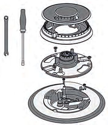
Dear Customer,

Thank you for purchasing one of our Accento ranges. This range was
conceived, designed and handcrafted in Italy.

Your selection of a Accento range confirms you are among a special group
who share a love and passion for cooking. This unique community shares
in the experience of creating quality dishes; dishes that will satisfy the
palate while bringing the warmth of families and friends together to share
and rejoice. Impress a loved one with your ability to combine flavours and
ingredients or experiment with new foods and different culinary techniques
to create unexpected pleasures.
EN

    TABLE OF CONTENTS                                  PAGE               WARNING

 1 - Special Warnings                                      2     This is the safety alert symbol. This symbol alerts you to
                                                                 potential hazards that can kill or hurt you and others. You
     Before Starting Installation                          2     can be killed or seriously injured if you don’t follow these
     Mobile Home Installation                              2     instructions.
     Recreational Park Trailers                            2

 2 - Product Dimensions and Cutout Requirements            3    READ AND SAVE THESE INSTRUCTIONS.
     Anti-Tip Bracket Installation                         5
                                                                To installer:
 3 - Installation Information                              6
                                                                Leave these instructions with the appliance.
 4 - Installation Instructions                             7
                                                                To customer:
 5 - Gas Requirement                                      11    Retain these instructions for future reference.
     Pressure Testing                                     12
     Pressure Test Method                                 12
                                                                          WARNING
     Gas Connection                                       13
                                                                 If the information in this manual is not followed exactly, a fire
 6 Conversion for LP or NG Gas                            14     or explosion may resulting in product and property damage
   Converting Appliance for Use with LP Gas               14     and / or personal injury or death.
   Replace Injectors (two ring flame burner)              14     Do not store or use gasoline or other flammable vapours and
   Replace injector on (one ring flame or burners)        14     liquids in the vicinity of this or any other appliance.
   Replace injector on (oven lower burner)                15
   Converting Appliances for Use with NG Gas              17
                                                                Anti-Tip Bracket Installation
   Pressure regulator conversion                          17
   INJECTORS POSITION                                     18
   Low Flame Adjustment                                   20
                                                                          WARNING
   Adjustment for Burners with one or two flame                  Tip Over Hazard
   rings:                                                 20     A child or adult can tip the range and be killed.
   Electric Gas Ignition                                  21     Ensure the anti-tip bracket is engaged when the range is
   The Burner Flames                                      21     moved.
                                                                 Do not operate range without anti-tip bracket installed and
 7 - Electrical Requirements                              22     engaged.
     General Information                                  22     Failure to follow these instructions can result in death or serious
     Electrical Connection                                22     burns to children and adults.
     Electrical Requirements                              23

IMPORTANT: Save these instructions for the local electrical
           inspector use.

INSTALLER:     Please leave this manual with owner for future
               reference.

OWNER:         Please keep this manual for future reference.
                                                                 To verify the anti-tip bracket is installed and engaged:
GLOSSARY OF TERMS:           NG - Natural Gas                    •   Slide range forward.
                             LP - Liquid Propane                 •   Look for the anti-tip bracket securely attached to floor or wall.
                                                                 •   Slide range back so rear range foot is under anti-tip bracket.
                                                                 •   See installation instructions for details.
Pay attention to these symbols present in this manual:

         DANGER

 You can be killed or seriously injured if you don’t
                                                                                                                 Anti-Tip Bracket
 IMMEDIATELY follow instructions.
                                                                                                                 Range Foot

                                                                                                                                         1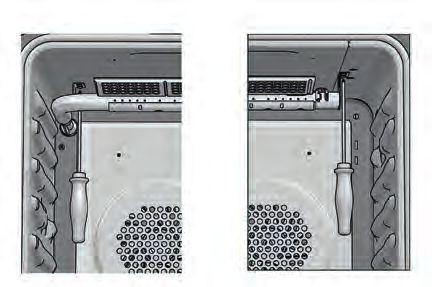
EN     1 - Special Warnings

                                        IMPORTANT INSTRUCTION
                                        Please read all instructions before using this appliance.

     Proper installation is your responsibility. Have a qualified       Copies of the standards listed may be obtained from:
     technician install this range.                                     **   National Fire Protection Association One Batterymarch Park
                                                                             Quincy, Massachusetts 02269
              IMPORTANT                                                 *** CSA International 8501 East Pleasant Valley Rd. Cleveland,
                                                                            OH 44131-5575
      - Observe all governing codes and ordinances.
                                                                        NOTE: This range is manufactured for use with Natural gas
      - Write down the model and serial numbers before installing
                                                                              or Propane.
        the range. Both numbers are on the serial rating plate refer
                                                                              To convert to LP (propane) or NG (natural gas), see
        to the illustration below.
                                                                              instructions in the gas conversion kit provided in the
                                                                              literature package. Proper gas supply connection
                                                                              must be available. See gas supply requirements.

                     LOCATION OF RATING PLATE                                    WARNING

                                                                         Before connecting the appliance to the gas supply line,
                                                                         ensure that its gas setting is appropriate.
                                                                         The type of gas adjusted and shipped from the factory is
                                                                         indicated on the rating plate.

                                                                        Mobile Home Installation

                                                                        The installation of this appliances must conform to the
                                                                        Manufactured Home Construction and Safety Standards, Title
                                                                        24 CFR, Part 3280 (formerly the Federal Standard for Mobile
                                                                        Home Construction and Safety; Title 24 HUD part 280); or
                                                                        when such standard is not applicable, the Standard for
                                                                        Manufactured Home Installations (Manufactured Home Sites,
                                                                        Communities and Setups), ANSI A225.1 - latest edition, or
                                                                        with local codes.
                                                                        When this range is installed in a mobile home, it must be
                                                                        secured to the floor during transit. Any method of securing the
     Before Starting Installation                                       range is adequate as long as it conforms to the standards listed
                                                                        above.
     • Check location where range will be installed. The location
       should be away from strong drafty areas, such as windows,        In Canada, the installation of this appliances must conform
       doors and strong heating vents or fans.                          with the current standards CAN/CSA-Z240 - latest edition, or
     • Electrical grounding       is   required.   See    “Electrical   with local codes.
       Requirements”
     • Assure that electrical installation is adequate and in
       conformance with National Electrical Code, ANSI/                 Recreational Park Trailers
       NFPA 70 - latest edition**, or Canadian Electrical Code,
       part 1 C22.1 (latest edition)*** and all local codes and         The installation of this appliances designed for Recreational
       ordinances.                                                      Park Trailers must conform with state or other codes or, in the
                                                                        absence of such codes, with the Standard for Recreational
     • Refer to manufacturer specifications of flexible gas line to
                                                                        Park Trailers, ANSI A119.5.
       ensure sufficient gas flow is provided to the appliance.
     • Assure that gas connection conforms with local codes and
       ordinances. In the absence of local codes, installations
       must conform with American National Standard, National
       Fuel Gas Code ANSI Z223.1/NFPA 54 - latest edition**
       Canadian CAN/ CGA_B 149.1 or CAN/CGA-149.2
       latest edition**

 2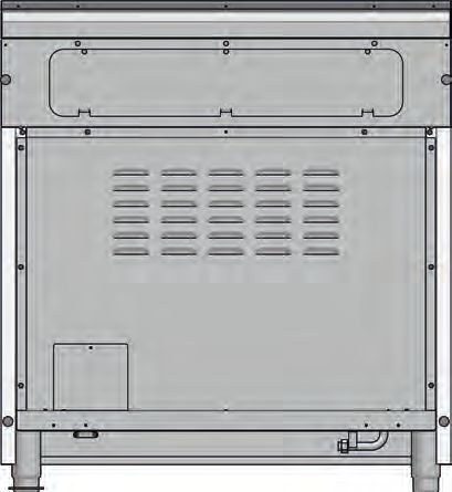
2 - Product Dimensions and Cutout Requirements                                      EN

                                                     PRODUCT DIMENSIONS

                       30” Wide Range Models                                    36” Wide Range Models

    29 3/4” (75.8)
                                                                    35 3/4” (91.0)

                                                 29 3/4” (75.6)

                                                 28 1/4” (719)

                                                                               7” (17.9)
9" (22.8) [optional]

3" ( 7.6) [optional]

1" ( 2.5)

                                                                                                        Max. 37 1/4” (94.7)
                                                                                                        Min. 35 3/8” (89.8)

                            3/8” (1)

                                                                               1 3/8” (3.5)
                                                                                     TO
                                                                               3 3/8” (8.5)

                                               25 3/4” ( 65.4)

                                               27 1/4” ( 69.1)

                                               47 3/4” (121.4)

                                                                                                                              3
EN   2 - Product Dimensions and Cutout Requirements

                                                             CUTOUT REQUIREMENTS

                                                                            C
                                                                                  Min. 48” (122)
                                                             Min. 30” (76.2)       Minimum to               Max. 13” (33)
                                                              To bottom of         combustibles
                                                             ventilation hood        when no
                                                                                    ventilation
                                                                                 hood is present**       Min. 18”
                                          Min. 18” (45.7)
                                                                                                          (45.7)

                                            Min. 6”                         A                              Min. 6”
                                            (15.2)                                                         (15.2)

                                                                                          3” (7.6)

                                                                                                                            *Suggested location
                                                                                                                             of utilities
                                                                                GAS    ELECTRIC
                    2” (5.1) max. protusion from
                   wall for gas or electrical supply                            B         B

                                                                                    4” 3/4 (12.3)

      ** NOTE: Ensure your installation also complies with local and national building and fire codes.
      If the surface of the entire back wall above the range and below the hood is not composed of a non-combustible material
      then the 9” accessory back guard must be used.
      *Consult local code for exact location requirements.
      OPENING WIDTH                A&C                 B
                                                                                              CAUTION
      Range 30”                    30"      (76.2) 6”          (15.2)
                                                                                    Pro style gas ranges exhaust oven combustion air through
      Range 36”                    36"      (91.4) 7”          (17.8)               the rear back guard. Therefore certain cooking conditions
                                                                                    may result in staining or discoloration of the backsplash.
     Note: Clearances from non-combustible materials are not                        Always choose a back splash material that is suitable
           part of the ANSI Z21.1 scope and not certied.                            for this application as Fulgor Milano will not be held
           Clearances to non-combustible materials must                             responsible for the discoloration of back splash.
           conform with local codes or, in the absence of local
           codes, with the National Fuel Gas Code, ANSI                          ADDITIONAL CLEARANCES:
           Z223.1/NFPA 54.
                                                                                 For island installation, maintain 2-½ in. minimum from
                                                                                 cutout to back edge of countertop and 3 in. minimum from
     Minimum clearances:
                                                                                 cutout to side edges of countertop (see top view).
     Above cooking surface (above 36” [91.4 cm])                                 For installation in a stepped island, 12” (30.5 cm) minimum
     • Sides - 6” (15.2 cm)                                                      clearance is required from the back or sides of the rangetop
     • Within 6” (15.2 cm) side clearance, wall cabinets no                      to a combustible riser. The island installation is not part of
       deeper than 13” (33.0 cm) must be minimum 18” (45.7                       the ANSI Z21.1 scope and not certified.
       cm) above cooking surface
     • Wall cabinets directly above product must be a minimum
       of 48” (122 cm) above cooking surface, no deeper than                                          FLUSH ISLAND INSTALLATION
       13” (33.0 cm).                                                                                               BACK
     • Rear - 0” with 9 ” backguard; 0” with non-combustible                                                                      min 2 1/2” (6.3)
       rear wall.
     Below cooking surface (36” [91.4 cm] and below)
     • Install with zero clearance between adjacent combustible                        min 3” (7.6)                               min 3” (7.6)
        construction below the cooking surface and the back
        and sides of the appliance.

 4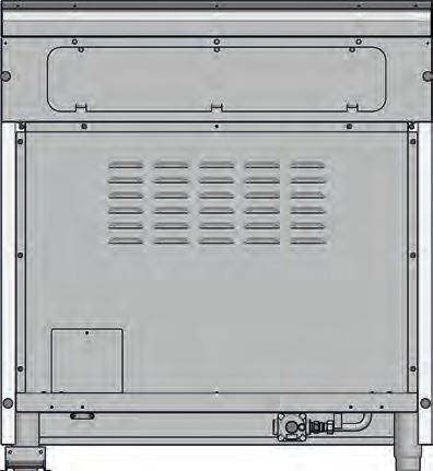
2 - Product Dimensions and Cutout Requirements                                                  EN

Before moving the range, protect any finished flooring and
secure oven door(s) closed to prevent damage.                                      WARNING

Vent hood Combinations:
It is recommended that these ranges be installed in
conjunctionwith a suitable overhead vent hood.
Due to the high heat capacity of this unit, particular attention
should be paid to the hood and ductwork installation to assure
it meets local building codes.
A hood with suitable capture area and capable of at least
450 cfm is suggested to effectively evacuate odors, steam and
heat. Choosing to install a hood of lower cfm or configured for
recirculating may compromise the effectiveness of eliminating
                                                                       To verify the anti-tip bracket is installed and engaged:
the aforementioned factors.
Note: some State / Provincial building codes will require              •    Slide range forward.
        make up air systems be installed for hoods above a             •    Look for the anti-tip bracket securely attached to floor or wall.
        certain cfm threshold (300 cfm is typical).                    •    Slide range back so rear range foot is under anti-tip bracket.
        It is your responsibility to understand and comply with        •    See installation instructions for details.
        the local requirements for gas, electrical and ventilation
        where these appliances are being installed.

         WARNING
 Air curtain or other overhead hoods, which operate by
 blowing a downward air flow on to a range, shall not be used
 in conjunction with ranges with gas cooktop other than when                                                            Anti-Tip Bracket
 the hood and range have been designed, tested and certified
 by an independent test laboratory for use in combination with                                                          Range Foot
 each other.
 Clearances to horizontal surfaces above the range, measured
 to the cooking surface are below. Failure to comply may                               ANTI-TIP BRACKET INSTALLATION
 result in fire hazard.
 • Installations without a hood require 48” (122) minimum
                                                                                                                                 WALL
    to combustibles.                                                                        BACKWALL                             ANCHOR
 • For other installations with a hood, refer to the hood
    installation instructions for specific hood clearances.                CABINET
                                                                           SIDEWALL

         CAUTION
 These ranges weigh up to 400 pounds. Some disassembly
 will reduce the weight considerably. Due to the weight and
 size of the range and to reduce the risk of personal injury or                             ANTI-TIP
                                                                           FLUSH
 damage to the product:                                                                     BRACKET

 TWO PEOPLE ARE REQUIRED FOR PROPER INSTALLATION.
                                                                           For Concrete or Cement Construction:
Anti-Tip Bracket Installation                                              You must use appropriate fastening hardware (not
                                                                           provided).
                                                                           Secure the bracket to the wall and/or floor with at least 4
         WARNING                                                           wood screws (provided).

 Tip Over Hazard
 A child or adult can tip the range and be killed.
 Ensure the anti-tip bracket is engaged when the range is
 moved.
 Do not operate range without anti-tip bracket installed and
 engaged.
 Failure to follow these instructions can result in death or serious
 burns to children and adults.                                          The anti-tip bracket should be inserted into the opening on
                                                                        the anti-tip brace on the range.

                                                                                                                                                5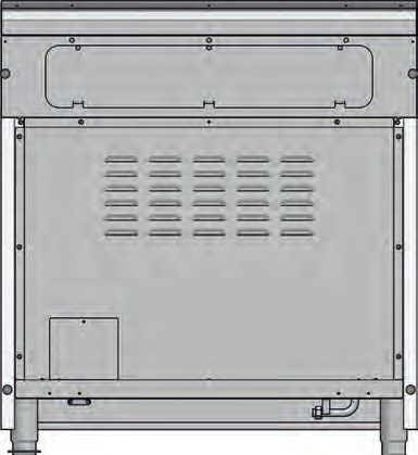
EN 3 - Installation Information
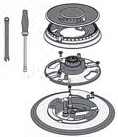
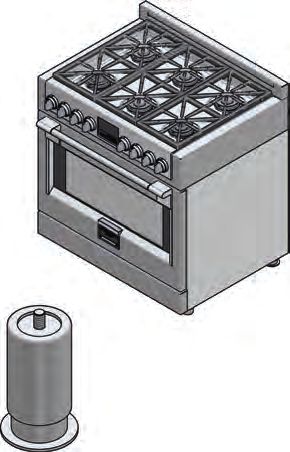
WARNING TOOLS WILL YOU NEED
• Excessive Weight Hazard
Use two or more people to move and install range.
Failure to do so can result in back or other injury.
• Cut Hazard
Beware of sharp edges. Use the polystyrene ends when
carrying the product. Failure to use caution could result in
minor injury or cuts.
Do not obstruct the flow of combustion air at the oven vent
nor around the base or beneath the lower front panel of the
range. Avoid touching the vent openings or nearby surfaces
as they may become hot while the oven is in operation. This
range requires fresh air for proper burner combustion.
NEVER cover any slots, holes or passages in the oven or
cover an entire rack with aluminum foil. Doing so blocks
air flow through the oven and may cause carbon monoxide
poisoning. Aluminum foil linings may also trap heat, causing
a fire hazard.
CHOOSING RANGE LOCATION Remove packaging materials and literature package from the
Carefully select the location where the range will be placed. cooktop before beginning installation.
The range should be located for convenient use in the kitchen, Remove Installation Instructions from the literature pack and
but away from strong drafts. read them carefully before you begin
Strong drafts may be caused by open doors or windows, or by
heating and/or air conditioning vents or fans. MATERIALS PROVIDED
IMPORTANT NOTE
Anti-tip bracket
When installing against a combustible surface, a minimum brace abd screws
riser is required for a the range, Follow all minimum
clearances to combustible surfaces shown in the illustration
on the previous pages.
Before moving the range, protect any finished flooring and
secure oven door(s) closed to prevent damage. Appliance Flare union Gasket
pressure adaptor
Do not lift or carry the range door by the door handle. regulator
To eliminate the risk of burns or fire by reaching over heated
surface units, cabinet storage space located above the surface MATERIALS REQUIRED (not provided)
units should be avoided. If cabinet storage is to be provided,
the risk can be reduced by installing a range hood that projects
horizontally a minimum of inches beyond the bottom of the
cabinets.
All openings in the wall or floor where the range is to be Joint Sealant Pipe Fittings Shut-Off Valve
installed must be sealed.
from 3-foot (* reccomended for 36’’ ranges) to 5-foot
maximum lengh, 5/8'' O.D. CSA-approved flexible metal
gas supply.
* If a longer connection line is used it may result in
noticeably reduced performance if using many of the
burners simultaneously.
NOTE: Purchase new flexible line; do not use previously used
flexible gas line.
64 - Installation Instructions EN
STEP 2
Do not tip the range on its side when installing the legs.The Open the top (2) and remove the accessories (3) then lift off
sidewalls are not designed to bear the weight of the range the cardboard sheath (4).
and will bend. Any damage as a result of tipping will not
be covered by warranty. Follow the method in the enclosed
installation Manual.
2
STEP 1
Cut the banding (1) and remove the Installation Instructions
from the top of range and read them carefully before you
begin.
CAUTION
3
Stand clear. The ends of the cut banding may snap toward you.
1
4
7EN 4 - Installation Instructions
STEP 3 STEP 5
Remove Installation Instructions (5) from the top of range and Slide back more and tilt back (9), putting the rear legs on the
read them carefully before you begin floor and then mount the front legs (10) while in this angled
position supported by the rear legs and the skid.
5
9
6
STEP 4 10
Slide the range back just enough to allow the rear feet to be
installed.
STEP 6
Remove the base while supporting the front of the range (11)
and lower to the floor in a controlled manner (12).
7
11
12
8
84 - Installation Instructions EN
STEP 7 STEP 8
In case it is necessary to move the range; using the foam and/ Some models come from the factory with the cast iron island
or cardboard packaging (13), replace them around the range style trim pre-installed. If not pre-installed, follow the installation
strategically to protect the finished surfaces of the range from instructions included with the island trim which also includes a
contact with the hand-truck and any straps around the unit screw and bracket kit. The image below shows the installation
(14). In the case of smaller ranges, you may use this technique of the optional stainless steel accessory back guard / trims
to remove the range from the skid and installing the legs (15). available in island style, 3” height and 9” height for purchase
Tilt the range to lower the hand-truck wheels off the skid. Place separately as accessories.
appliance runners on the floor at the left and right sides in
front of the opening when moving into final position to protect
flooring. The oven door(s) add(s) a great deal to the overall
weight of the range, you may find it helpful to remove the
doors if moving the range a significant distance. Refer to the
included instruction manuals for how to remove and reinstall
the doors.
13
9” 3”
14
15
9EN 4 - Installation Instructions
STEP 9
After completing the electrical and gas connections (see
included instructions) measure the four corners in cutout area
to verify if flooring is level. Adjust the leveling legs to the desired
height and ensure range is level. Turn the bottom section of
each leg counter-clockwise to raise the leg and clockwise to
lower it.
Ensure floor is protected. Slide unit into place making sure to
engage the anti-tip bracket.
STEP 10
Hook tabs on bottom of toekick into slots on either side of the
frame and rotate up until the magnets at the top of toekick
make contact and hold it in place securely
105 - Gas Requirement EN
QUALIFIED SERVICE MAN OR GAS APPLIANCE INSTALLER
MUST MAKE THE GAS SUPPLY CONNECTION.
Leak testing of the appliance shall be conducted by the installer
according to the instructions given. GAS SHUT OFF VALVE
You must install the supplied connection parts seen here in
this configuration to the main gas manifold on the appliance. OPEN POSITION
Issues arising from a failure to do so will not be covered by
warranty.
Do not install the pressure regulator backwards as the gas will
LY
not flow correctly. Check that the arrow on the back points in SUPP
GAS
the direction of gas flow.
Parts required for connection from gas supply to regulator are N CE
PPLIA
the responsibility of the installer / owner TO A
All supply piping, except as noted, should use common
National Pipe Thread (N.P.T.). For all pipe connections use an
approved pipe joint compound resistant to the action of LP gas.
Appliance This appliance is designed for use with NG gas or LP gas.
The gas pressure regulator is supplied with this appliance.
It must be installed in the gas ahead of the manifold entrance.
It is pre-set for use with natural gas. To use it with different
gas it must be converted, as described in the Gas Conversion
Appliance Flare union paragraph.
pressure regulator adaptor Gasket
If at any time the appliance is to be used with a different type
of gas, all the conversion adjustments must be made by a
qualified technician before attempting to operate the range
with that gas.
The gas should be supplied to the appliance’s pressure
regulator at line pressure between 6 and 14 inches of water
column for
ATTENTION
NG, and between 11 and 14 inches of water column for LP.
Use Teflon tape rated for gas applications at all threaded
connections. GAS REQUIREMENTS
Do not overtighten the connection at the manifold or you NATURAL GAS WC
could damage the gasket causing a leak. Manifold Pressure 5" (12.5 mb)
Min Line Pressure 6" (15 mb)
Max Line Pressure 14" (34.9 mb), .5 psi (3.5 kPa)
WARNING
LP GAS WC
If the line pressure supplying the appliance pressure regulator
exceeds 14 inches W.C. (any gas), an external regulator Manifold Pressure 10” (25 mb)
must be installed in the gas line ahead of the appliance Min Line Pressure 11” (27.4 mb)
regulator to reduce the pressure to no more than 14 inches Max Line Pressure 14” (34.9 mb), .5 psi (3.5 kPa)
W.C. Failure to do this can result in malfunction and damage
to the appliance.
Important Notes for Gas Connection
The appliance and its individual gas shutoff valve must be
disconnected from the gas supply piping system during any
pressure testing of that system at test pressures in excess of 1/2
psi (3.5 kPa).
The appliance must be isolated from the gas supply piping
system by closing its individual manual shut-off valve during
any pressure testing of the gas supply piping system at test
pressures equal to or less than 1/2 psi (3.5 kPa).
11EN 5 - Gas Requirement
LOCATION OF GAS RATING PLATE Pressure Testing
The appliance must be isolated from the gas supply piping
system by closing its individual manual shut-off valve during
any pressure testing of the gas supply piping system at test
pressures equal to or less than 1/2 PSIG (3.5 kPa).
This appliance, as well as its individual shut-off valve, must be
disconnected from the gas supply piping system during any
pressure testing of the system at test pressures in excess of 1/2
PSIG (3.5 kPa).
When checking appliance regulator function, make certain
pressure of natural gas supply is between 6 and 14 inches of
water column or, if converted for LP gas, between 11 and 14
inches.
THE PRESSURE TESTING SHOULD BE PERFORMED BY
MEANS OF THE INJECTOR THREAD ZONE
EXPLODED VIEW DUAL BURNER
1
2
IMPORTANT
NEVER REUSE OLD CONNECTORS WHEN INSTALLING THIS A
RANGE.
To reduce the likelihood of gas leaks, apply teflon tape or a
thread compound approved for use with LP or Natural gases
to all threaded connections.
Apply a non-corrosive leak detection fluid to all joints and
fittings in the gas connection between the supply line shut-off
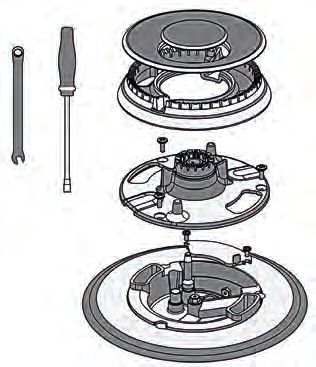
valve and the cooktop inlet. EXPLODED VIEW SINGLE BURNER
Check for leaks!
Bubbles appearing around fittings and connections will 1
indicate a leak. If a leak appears, turn off supply line gas
shut-off valve, tighten connections, turn on the supply line gas 2
shutoff valve, and retest for leaks. Never test for gas leaks
with an open flame.
NEVER TIGHTEN TO MORE THAN 35 ft lbs OF TORQUE
A
CAUTION
Do not attempt to attach the flexible connector directly to an
external pipe thread.
Connection requires flare union adapters. Pressure Test Method
For Massachusetts Installations:
• Remove grate and burner cap (1).
• Remove aluminum gas spreader (2).
1. Shut-off valve must be a “T” handle gas valve. • Temporarily remove the injectors (A).
2. Flexible gas connector must not be longer than 36 inch. • Connect the pressure Test instrument into injector holder
thread zone (M6x0,75).
3. Not approved for installation in a bedroom or a bathroom
unless unit is direct vent. • Check if the cooktop has the correct pressure.
• Fix the injector removed for testing and replace the parts in
the right position.
125 - Gas Requirement EN
Gas Connection A 1/2” NPT x 1/2” flare union adapter is required at each end
of the flexible connector.
• Thread the appliances pressure regulator with 1/2” male If a flexible connector is used assure that both the appliance
end connection both supplied with this appliance. pressure regulator and manual shut-off valve are joined solidly to
• Join the pressure regulator to the entrance threads of the other permanent hard piping (either gas supply or the appliance
Gas Manifold with gasket supplied with this appliance. manifold) so as to be physically stationary.
The regulator is marked with a directional arrow indicating
correct direction of gas flow. Ensure the appliance regulator
is installed with the arrow pointing toward the gas manifold
CAUTION
entrance. Do not attempt to attach the flexible connector directly to an
• Connect a manual shut-off valve to the gas supply in an external pipe thread.
accessible location for turning on or shutting off gas to the Connection requires flare union adapters.
appliance.
• Install a coupling between the regulator and the shutoff valve
MAXIMUM GAS POWER
to complete the connection.
NATURAL GAS
• Assure all pipe joint connections are gas tight.
30” 92,000 Btu/h
• Check alignment of valves after connecting the cooktop to the
36” 133,500 Btu/h
gas supply to be sure the manifold pipe has not been moved.
PROPANE GAS
FOR ALTERNATIVE PIPING METHODS TO CONNECT THE
30” 76,000 Btu/h
APPLIANCE TO THE GAS SUPPLY, A TRAINED SERVICE
36” 111,500 Btu/h
TECHNICIAN OR GAS APPLIANCE INSTALLER MUST MAKE THE
GAS SUPPLYCONNECTION. Leak testing of the appliance shall be
conducted by the Installer according to the Instructions given. For Massachusetts Installations:
1. Shut-off valve must be a “T” handle gas valve.
Unless prohibited by local codes or ordinances, a new A.G.A.
2. Flexible gas connector must not be longer than 36 inches.
- Certified, flexible metal appliance connector may be used to
connect this appliance to its gas supply. 3. Not approved for installation in a bedroom or a bathroom
The connector must have an internal diameter not less than unless unit is direct vent.
nominal 1/2” NPT pipe and be no more than 5 feet in length.
GAS CONNECTION
FLARE UNION ADAPTOR APPLIANCE PRESSURE REGULATOR
FLARE UNION ADAPTOR
GASKET
FLARE UNION ADAPTOR
FLEXIBLE APPLIANCE CONNECTOR
(5 FT.) MAX, (1.52 m) MAX
MANIFOLD SHUTOFF VALVES
GASKET
FLARE UNION ADAPTOR
FLEXIBLE APPLIANCE CONNECTOR
(5 FT.) MAX, (1.52 m) MAX
APPLIANCE PRESSURE REGULATOR
MANIFOLD SHUTOFF VALVES
13EN 6 - Conversion for LP or NG Gas
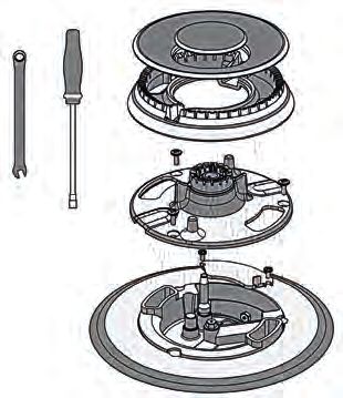
Converting Appliance for Use with LP Gas EXPLODED VIEW DUAL BURNER
WARNING
Conversion is to be performed by an AUTHORIZED
SERVICER (or other qualified agency) in accordance with the
manufacturer’s instructions and all codes and requirements of 1
the authority having jurisdiction. Failure to follow instructions
could result in serious injury or property damage.
The qualified agency performing this work assumes
responsibility for this conversion. 2
B
A
CAUTION
Before proceeding with the conversion, shut off the gas supply
to the appliance prior to disconnecting the electrical power
If this appliance is to converted for use with gas LP (propane
or butane), each of the following modifications must be Replace injector on (one ring flame or burners)
performed:
Gas conversion label (aluminium) to be placed on the back of 1. Remove the grates and burner cups.
the appliance, near the data plate, after conversion has been 2. Remove aluminum gas spreader.
carried out;
3. Loosen injector by turning 9-32” (7 mm) nut driver counter
clockwise.
Replace Injectors (two ring flame burner) 4. Install the injectors supplied with this appliances in the
appropriate burner. The injectors have small number
1. Remove the grates and burner caps. stamped on the side, this number codes the orifice diameter
and its correct burner location (see figure on page 18).
2. Remove aluminium gas spreader.
5. Turn clockwise to tighten (tighten to a torque of 15 to 20
3. Remove the three screws from the simmer gas spreader
inch-lbs).
(1).
4. Remove the two screws of the injector cover (2). 6. Replace all parts following the reverse order.
5. Remove injector (A) by using a 9-32” (7 mm) nut driver 7. Save the orifices removed from the appliance for future use.
counter clockwise.
6. Remove injector (B) by using a 9-32” (7 mm) box wrench EXPLODED VIEW SINGLE BURNER
counter clockwise.
1
7. Install the injectors supplied with this appliance in the
appropriate burner. The injectors have small numbers
stamped on the side, this number corresponds with the 2
orifice diameter and its correct burner location (refer to
illustrations in the section: “Injectors Position”).
8. Turn clockwise to tighten (tighten to a torque of 15 to 20
inch-lbs). A
9. Replace all parts following the reverse order.
10. Save the injectors removed from the appliances for
future use.
146 - Conversion for LP or NG Gas EN
Replace injector on (oven lower burner)
1. Remove the burner cover plate. 4. Remove the nozzle by turning 9-32” (7 mm) nut driver
counter clockwise.
5. Install the injectors supplied with this appliances in the
appropriate burner. The injectors have small number
stamped on the side, this number codes the orifice diameter
and its correct burner location (see figure of the paragraph
“Injectors position”).
6. Turn clockwise to tighten (tighten to a torque of 15 to 20
inch-lbs)
2. Disconnect both heat sensor and the ignition spark plug.
3. Remove the screw securing the oven burner and withdraw
the burner from the support.
7. Replace all parts following the reverse order. Save the
injectors removed from the appliances for future use.
15EN 6 - Conversion for LP or NG Gas
Replace injector on (oven grill burner)
1. Remove the door as described in the paragraph “Door 3. Remove the nozzle by turning 9-32” (7 mm) nut driver
removal” counter clockwise.
2. Remove the screws securing the grill burner and withdraw
the burner from the support.
4. Install the injectors supplied with this appliances in the
appropriate burner. The injectors have small number
stamped on the side, this number codes the orifice diameter
and its correct burner location (see figure of the paragraph
“Injectors position”).
5. Turn clockwise to tighten (tighten to a torque of 15 to 20
inch-lbs)
6. Replace all parts following the reverse order paying
attention to the correct placement of the burner.
7. Save the injectors removed from the appliances for future
use.
166 - Conversion for LP or NG Gas EN
Proceed to Pressure Regulator Conversion noting the LP /
PRESSURE REGULATOR CONVERSION
Propane position to complete the conversion.
After replacing the injectors adjust the burner flame (see Low
Flame Adjustment paragraph).
Check the appearance of each burner’s flame at HILO settings, CAP
if the flame appears too large or too small make sure that all
GASKET
steps were completed correctly. NG POSITION
LP/PROPANE POSITION
Converting Appliances for Use with NG Gas
If this appliance should be converted for use with gas NG
(natural gas), each of the following modifications must be
performed.
1. Convert the pressure regulator to NG position as per the PRESSURE REGULATOR
section “Pressure Regulator Conversion”.
2. Replace all injectors following the step described on the
previous pages, observe the number stamped on the side, PLUG
this number corresponds to the orifice diameter and its
correct burner location (refer to the illustrations in section:
“Injectors Position”).
3. Adjust the burner flame (see Low Flame Adjustment section).
Check the appearance of each burner’s flame at HI - LO
settings, if the flame appears too large or too small make sure NG LP
that all steps were completed correctly.
Before replacing the regulator cap, check if the position
of plug is suitable for the gas
Pressure regulator conversion
The appliances is designed for use with NG gas or LP gas. The
gas pressure regulator is supplied. It must be installed in the
gas supply line ahead of the manifold entrance.
It is pre-set for use with the gas as indicated on the appliance
label supplied with the appliance. For use with different gas
the appliance must be converted.
For the pressure regulator conversion follow the instructions
below:
• Disconnect all electrical power, at the main circuit breaker
or fuse box.
• Shut off the gas supply to the cooktop by closing the manual
shut-off valve.
• Adjust the pressure regulator, by following the instruction
(see figure)
1. Unscrew the regulator cap
2. Unscrew the plastic conversion plug from the cap turn
over and screw back (wide section away from cap for
LP and against cap for NG) see figures below.
3. Replace the regulator cap ensuring gasket is in place.
17EN 6 - Conversion for LP or NG Gas
INJECTORS POSITION
NG- DUAL FLAME RING 30”
SIMMER 72 180
175
MAIN FLAME 180
210
SIMMER 72
180
MAIN FLAME 180
NG- DUAL FLAME RING 36”
180 SIMMER 72 180
MAIN FLAME 180
200
230
SIMMER 72 SIMMER 72
MAIN FLAME 180 180 MAIN FLAME 180
* depending on the model
186 - Conversion for LP or NG Gas EN
INJECTORS POSITION
LP- DUAL FLAME RING 30”
SIMMER 50 105
110
MAIN FLAME 105
125
SIMMER 50
105
MAIN FLAME 105
LP- DUAL FLAME RING 36”
105 SIMMER 50 105
MAIN FLAME 105
120
140
SIMMER 50 SIMMER 50
MAIN FLAME 105 105 MAIN FLAME 105
19EN 6 - Conversion for LP or NG Gas
Low Flame Adjustment
4. Insert a slender, thin-blade screwdriver into the recess
DANGER behind the control knob (A or B) and engage blade with
slot in adjusting screw.
Lighting gas burners with a match is dangerous.
You should match light the burners only in an emergency. 5. Turn adjusting screw to set flame size:
Light a match and hold the flame near the burner you want
to light. Wooden matches work best. • clockwise to reduce
Push in and turn the control knob slowly. • counterclockwise to increase
Be sure you are turning the correct knob for the burner you
6. Replace control knob when adjustment is completed.
are lighting.
Adjustment for Lower Oven Burner:
NOTE: If the burner does not light within five seconds, turn the
knob off and wait one minute before trying again. 1. Light burner and set control knob for low flame.
2. Remove control knob from valve stem.
CAUTION
Conversion from natural gas to liquid gas
If you attempt to measure the inner cone of the flame, please
use caution. 3. insert the screwdriver in the hole in the front wall of the
Burns could result. instrument panel and turn regulation screw A clockwise.
This appliance is shipped from the factory with low and Conversion from liquid gas to natural gas
medium flame settings adjusted.
If further adjustment is necessary, proceed as follows: 4. Light the oven with thermostat set to 250 °C for at least 10-
15 minutes.
Then, turn the thermostat to the minimum position and turn the
Adjustment for Burners with one or two flame bypass screw A counterclockwise until you see a reduced by
rings: stable flame.
NOTE: Check that the flame does not go out when the door of the
1. Light burner and set control knob for low flame. oven is opened and closed repeatedly. If the flame goes
2. Remove control knob from valve stem. out, slight increase the minimum regulation setting.
3. Remove knob seat from control panel.
5. Replace control knob when adjustment is completed.
ADJUSTMENT FOR COOKTTOP BURNERS
ADJUSTMENT FOR LOWER OVEN BURNER
206 - Conversion for LP or NG Gas EN
Proper adjustment will produce a stable, steady blue flame of
minimum size.
The final adjustment should be checked by turning the knob
from high to low several times without extinguishing the flame.
This adjustment, at low setting, will automatically provide the
proper flame size at medium setting.
After Conversion steps have been completed, check the
appearance of each burner’s flame at the HI and LO settings,
if the flames appear too large or too small
review each step to make sure it was completed correctly.
NOTE: To obtain the correct minimum setting with LP gas, turn
clockwise tightening the valve(s) fully with the thin-blade
screwdriver into the recess behind control knob (A and /
or B).
Electric Gas Ignition The Burner Flames
The gas burners use an electric ignition device located near Turn each burner on. Flames should be blue in color with no
each burner ensures burners ignite automatically. trace of yellow. The burner flames should not flutter or blow
away from the burner The inner cone of the flame should be
between 1/2” and 3/4” long.
ELECTRIC IGNITION BURNER FLAMES
1/2” to 3/4” 1/2” to 3/4”
BURNER
BURNER
See Use & Care manual for better explanation and its control.
21EN 7 - Electrical Requirements
General Information Electrical Connection
This appliance must be supplied with the proper voltage and An adequate electrical supply and outlet must be used to
frequency and connected to an individual, properly grounded operate the electrical parts of your appliance.
branch circuit, protected by a circuit breaker or fuse having
amperage as noted on the rating plate. We recommend you
have the electrical wiring and hookup of your appliance
WARNING
connected by a qualified electrician.
After installation, have the electrician show you where your
main appliance disconnect is located. Check with your local
utilities for electrical codes which apply in your area. Failure to
wire your cooktop according to governing codes could result
in a hazardous condition.
If there are no codes, your appliance must be wired and fused
to meet the requirements of the National Electrical Code,
ANSI/NFPA No. 70 - Latest edition.
You can get a copy by writing:
National Fire Protection Association
Battery march Park
Quincy. MA 02269
Electrical Grounding Instruction Plug into a grounded 3
In Canada your appliance must be wired and fused to meet
prong outlet.
the requirements of the Canadian Electrical Code.
Be sure the installation of this product in a mobile home - Do not remove ground prong.
conforms with the Manufactured Home Construction and - Do not use an adapter.
Safety Standard, Title 24 CFR, Part 3280.
- Do not use an extension cord.
If this standard does not apply, you must follow the standard
for Manufactured Home Installations, ANSI A225.1 and Failure to follow these instructions can result in death, fire, or
Manufactured Home Installations, Sites and Communities and electrical shock.
ANSI/NFPA 501A or with local codes.
You can get a copy of the Federal Standard by Writing:
Office of Mobile Home Standards IMPORTANT
HUD Building
451 7th Street, S.W. FOR PERSONAL SAFETY, THIS APPLIANCE MUST BE
PROPERLY GROUNDED.
Washington, D.C. 24010
LOCATION OF RATING PLATE
The power cord of this appliance is equipped with a 3-prong
(grounding) plug which must be used with a properly grounded
3-hole outlet with a standard 120 Volt, 60 cycle AC household
current. If you do not have a 3-hole grounded outlet, have a
qualified electrician change your old one.
A grounding adaptor will be needed to convert the old one
until the outlet can be replaced. This method is only temporary,
and a qualified electrician should test it to be sure it meets
requirements.
227 - Electrical Requirements EN
Electrical Requirements
Do not under any circumstances cut or remove grounding
prong from the appliance cord. WARNING
• If cold water pipe is interrupted by plastic, non metallic
gaskets, union connections or other insulating materials,
PLUG POWER SUPPLY CORD
DO NOT use for grounding.
• DO NOT ground to a gas pipe.
• DO NOT have a fuse in the NEUTRAL or GROUNDING
circuit. A fuse in the NEUTRAL or GROUNDING circuit
could result in an electrical shock.
• Check with a qualified electrician if you are in doubt as to
whether the appliance is properly grounded.
N • Failure to follow these instructions could result in serious
injury or death.
L
CAUTION
Do not repair or replace any part of the appliance unless
specifically recommended in the manual. All other servicing
Grounding prong should be done by a qualified technician. This may reduce
the risk of personal injury and damage to the appliance.
Never modify or alter the construction of the appliance by
removing panels, wire covers, screws, or any other part of
the product.
23EN 24
FR

    TABLES DES MATIERES                                       PAGE            AVERTISSEMENT
 1 - Avertissement Spéciaux                                     2     Ce symbole signifie que la sécurité est en danger. Il signale
     Avant de Procéder à l’Installation                         2     les risques potentiels qui peuvent entraîner la mort ou des
     Installation autocaravane                                  2     blessures à l’opérateur ou aux autres.
                                                                      Si vous ne suivez pas ces instructions à la lettre, vous courez
     Micro-maisons préfabriquées                                2
                                                                      le risque de mourir ou d’être sérieusement blessé.
 2 - Dimensions et Dispositions pour la Découpe                 3
     Instructions d’installation des supports anti-bascules     5    BIEN LIRE CES INSTRUCTIONS ET LES CONSERVER.
 3 - Consignes d’installation                                    7
                                                                     À l’installateur :
 4 - Instructions d’Installation                                8    Laissez ces instructions avec l’appareil.
 5 - Conditions Requires Gaz                                   12
                                                                     Au client :
     Vérification de la Pression                               13    Gardez ces instructions comme référence future.
     Méthode de Test de Pression                               13
     Raccordement du Gaz                                       14
                                                                              AVERTISSEMENT
 6 - Conversion Gaz PL ou Gaz Naturel                           15
     Conversion de l’Appareil pour Fonctionner au                     Le respect minutieux des indications fournies dans ce manuel
     Gaz PL                                                    15     est indispensable pour éviter le risque de feu ou d’explosion
     Remplacez un injecteur (brûleur avec deux                        susceptible d’endommager les biens et les produits et de
     anneaux de flamme)                                        15     provoquer des blessures, voire même la mort.
     Remplacez un injecteu                                            Ne pas stocker ou utiliser de l’essence ou d’autres liquides
      (couronne de flamme ou brûleurs)                         15     inflammables à proximité de cet appareil ou de tout autre
                                                                      appareil électroménager.
     Conversion des Appareils pour Une Utilisation
                                                               18
     avec Gaz Naturel
     Conversion du régulateur de pression                      18    Instructions d’installation des supports anti-bascules
     Position des Injecteurs                                   19
     Réglage Petite Flamme                                     21             AVERTISSEMENT
     Réglage pour brûleurs avec un ou deux anneaux
     de flamme:                                                21     Risque de basculement
                                                                      Un enfant ou une personne adulte peut faire basculer la
     Allumage à gaz électrique                                 22
                                                                      cuisinière, ce qui peut causer un décès. S’assurer que le
     Les Flammes du Brûleur                                    22     dispositif antibascule est réengagé lorsque la plage est
 7 - Conditions Requises Electricité                           23     déplacée. Ne pas faire fonctionner la cuisinière si la bride
     Information Général                                       23     antibasculement n’est pas installée et engagée. Le non-respect
                                                                      de ces instructions peut causer un décès ou des brûlures
     Branchement Electrique                                    23
                                                                      graves aux enfants et aux adultes.
     Requises Electricité                                      24

IMPORTANT:        Gardez ces instructions pour une utilization
                  d’inspection électrique locale

INSTALLATEUR: Veuillez laisser ce manuel au propriétaire
              pour de futures références.                             Pour vérifier que la bride antibasculement est bien installée
                                                                      et engagée :
PROPRIETAIRE: Veuillez garder ce manuel pour de futures               • Faire glisser la cuisinière vers l’avant.
              références.                                             • Vérifier que la bride antibasculement est bien fixée au
                                                                         plancher ou au mur.
LEXIQUE:          NG - Gaz naturel                                    • Faire de nouveau glisser la cuisinière vers l’arrière de
                  LP - Propane liquide                                   sorte que le pied de la cuisinière se trouve sous la bride
                                                                         antibasculement.
Veuillez prêter attention à ces symboles que vous rencontrerez        • Voir les instructions d’installation pour plus de détails.
dans ce manuel :

         DANGER
 Si vous ne suivez pas IMMEDIATEMENT ces instructions,
 vous courez le risque de mourir ou d’être sérieusement                                                      Bride antibasculement
 blessé.
                                                                                                             Pied de la cuisinière

                                                                                                                                        1
FR 1 - Avertissement Spéciaux
INSTRUCTION IMPORTANT
Veuillez lire les instructions avant toute utilisation.
Il est de votre responsabilité d’installer l’appareil correctement. CAN/CGA-149.2 dernière édition***.
Confiez l’installation de cette cuisinières à un technicien qualifié. Vous pouvez demander une copie des standards répertoriés à:
** National Fire Protection Association One Batterymarch Park
Quincy, Massachusetts 02269
AVERTISSEMENT
*** CSA International 8501 East Pleasant Valley Rd. Cleveland,
- Respecter les règlements et ordonnances en vigueur. OH 44131 – 5575
- Avant l’installation de la cuisinière, noter le modèle et
les numéros de série. Les deux numéros se trouvent sur NOTE: Cette cuisinières est fabriquée pour fonctionner au
la plaque de données dans la position indiquée dans la gaz naturel*.
figure ci-dessous. Si elle doit être raccordée au gaz propane/PL,
ffectuez la conversion en suivant les instructions
rapportées dans le kit de conversion gaz fourni avec
POSITION DE LA PLAQUE SIGNALÉTIQUE
les explications.
Une canalisation de fourniture de gaz correcte doit
être disponible. Voir «Conditions requises fourniture
gaz».
WARNING
Avant de raccorder le dispositif à la ligne d’amenée du gaz,
vérifier que le type de gaz est réglé correctement. Le type
de gaz programmé et envoyé de l’usine est indiqué sur la
plaque signalétique.
Installation autocaravane
L’installation de cette table de cuisson doit être conforme
aux Normes de Construction et de Sécurité des Habitations,
titre 24 CFR, Partie 3280 (jadis la Norme Fédérale pour la
Avant de Procéder à l’Installation Construction et la Sécurité des Autocaravanes; titre 24HUD
partie 280); ou lorsque de telles normes ne sont pas
• Vérifiez l’endroit où la cuisinières sera installée. La table de applicables, la Norme pour les Installations des Habitations
cuisson ne doit pas se trouver dans une zone de courants (Emplacements, Communautés et Structures Habitations),
d’air forts, par exemple de fenêtres ou de portes ni près de ANSI 225.1 - dernière édition ou aux réglementations locales.
calorifères ou de ventilateurs. Dans le cas de l’installation de cette cuisinière dans une
résidence mobile, la cuisinière doit être fixée au plancher
• L’appareil doit nécessairement être relié à la terre. Voir
durant tout déplacement du véhicule. Toute méthode de fixation
«Conditions requises électricité».
de la cuisinière est adéquate dans la mesure où elle satisfait
• Se reporter aux spécifications du fabricant de la ligne aux critères des normes mentionnées ci-dessus.
flexible de gaz pour s’assurer qu’un débit de gaz suffisant
est fourni à l’appareil. Au Canada, l’installation de cette table de cuisson doit être
• Veuillez vous assurer que l’installation électrique est conforme aux normes en vigueur CAN/CSA-Z240 - dernière
adéquate et conforme à la Réglementation Électrique édition ou aux réglementations locales.
Nationale ANSI/NFPA 70 – dernière édition** ou à la
Réglementation Électrique du Canada, C22.1 – 1982 et
C22.2 N° 01982 (ou dernière édition)*** et à tous les Micro-maisons préfabriquées
règlements et ordonnances en vigueur localement.
• Assurez-vous que le raccordement de gaz est conforme aux L’installation de ces dispositifs conçus pour micro-maisons
règlements et ordonnances en vigueur localement. En l’absence préfabriquées doit se faire conformément aux réglementations
de règlements locaux, l’installation doit être conforme au nationales ou autres ou, à défaut, à la norme en matière de
Standard National Américain, à la Réglementation Nationale micro-maisons préfabriquées ANSI A119.5.
Essence Gaz ANSI Z223.1 – NFPA 54 dernière édition** ou
22 - Dimensions et Dispositions pour la Découpe FR
DIMENSIONS DU PRODUIT
Modèles de cuisinière 30” Modèles de cuisinière 36”
29 3/4” (75.8)
35 3/4” (91.0)
29 3/4” (75,6)
28 1/4” (719)
7” (17,9)
9" (22,8) [optionnel]
3" ( 7,6) [optionnel]
1" ( 2,5)
Max. 37 1/4” (94,7)
Min. 35 3/8” (89,8)
3/8” (1)
1 3/8” (3,5)
À
3 3/8” (8,5)
25 3/4” ( 65,4)
27 1/4” ( 69,1)
47 3/4” (121,4)
3FR 2 - Dimensions et Dispositions pour la Découpe
Dispositions pour la découpe
C
Min. 48” (122) Max. 13” (33)
Min. 30” (76,2) Minimum sur
Jusqu’au bas combustibles en
de la hotte l'absence de hotte
de ventilation**
Min. 18” (45,7) Min. 18” (45,7)
Min. 6” Min. 6”
(15,2) A (15,2)
3” (7,6)
*Position suggérée des
équipements
Bordure minimale de 2 po (5,1) GAZ ÉLECTRIQUE
depuis le mur pour l’alimentation
en gaz ou électrique B B
4” 3/4 (12,3)
** REMARQUE : Assurez-vous que votre installation est également conforme aux codes locaux et nationaux du bâtiment et de prévention contre les
incendies.
Si la surface du mur arrière tout entier au-dessus de la cuisinière et au-dessous de la hotte n’est pas composée d’un matériau incombustible,
la protection arrière accessoire de 9 pouces doit être utilisée.
*Consulter les réglementations locales pour les exigences exactes de localisation.
LARGEUR D’OUVERTURE A&C B
ATTENTION
Cuisinière 30 po 30" (76.2) 6” (15.2)
Les cuisinières à gaz de style professionnel évacuent l’air
Cuisinière 36 po 36" (91.4) 7” (17.8)
de combustion du four par la protection arrière arrière.
Par conséquent, certaines conditions de cuisson peuvent
Remarque: Les distances par rapport aux matières non entraîner des taches ou une décoloration du dosseret.
combustibles n’entrent pas dans le cadre de Choisissez toujours un matériau anti-éclaboussures adapté
l’ANSI Z21.1 et ne sont pas certiées. à cette application car Fulgor Milano ne sera pas tenu
La distance par rapport aux matériaux non responsable de la décoloration des éclaboussures arrière.
combustible doit respecter les réglementations
locales ou, en l’absence de celles-ci, avec le ESPACE SUPPLÉMENTAIRES:
« National Fuel Gas Code », ANSI Z223.1/
Pour une installation en îlot, maintenir une distance minimum
NFPA 54.
de 6.3 cm (2 ½ po) entre le bord et le dos du comptoir et
7.6 cm (3 po) minimum sur les côtés du comptoir (voir vue
Dégagements minimums d’une construction: de dessus).
Au-dessus de la surface de cuisson [au-dessus de 36 po (91.4 cm)] Pour une installation sur un îlot, un espace de minimum 12”
• Côtés - 6 po (15.2 cm) (30,5 cm) est nécessaire de l’arrière ou des côtés de la
• Avec un dégagement latéral de 6 po (15.2 cm) ou moins, cuisinière pour le brûleur.
les placards muraux ne mesurant pas plus de 13 po (33 L’installation de îlot ne fait pas partie de la norme ANSI
cm) de profondeur doivent se trouver à 18 po (45,7 cm) Z21.1 portée et pas certié.
minimum au-dessus de la surface de cuisson
• Les armoires murales juste au-dessus du produit doivent INSTALLATION ÉBARBER
se trouver à 48 po (122 cm) minimum au-dessus de la
surface de cuisson, ne mesurant pas plus de 13 po (33 DOS
min 2 1/2” (6,3)
cm)
• Arrière - 0 po avec dosseret de 9 po ou étagère
supérieure; 0 po avec paroi arrière non combustible.
min 3” (7,6) min 3” (7,6)
Sous la plaque de cuisson (36” [91.4 cm] et au-dessous)
• Installation à dégagement nul entre la construction
combustible adjacente sous la surface de cuisson et les
parties arrière et latérale de l’appareil.
42 - Dimensions et Dispositions pour la Découpe FR
Instructions d’installation des supports anti-bascules
Avant de déplacer la cuisinière, protégez tout plancher fini et
fixez la (les) porte(s) du four en position fermée pour éviter tout AVERTISSEMENT
dommage.
Risque de basculement
Disposition de hotte d’extraction: Un enfant ou une personne adulte peut faire basculer la
Il est recommandé d’installer ces cuisinières en conjonction cuisinière, ce qui peut causer un décès. S’assurer que le
avec une hotte à évacuation appropriée en hauteur. En raison dispositif antibascule est réengagé lorsque la plage est
de la capacité thermique élevée de cet appareil, une attention déplacée. Ne pas faire fonctionner la cuisinière si la bride
particulière doit être prêtée à l’installation de la hotte et des antibasculement n’est pas installée et engagée. Le non-respect
conduits pour s’assurer qu’elle respecte les codes du bâtiment de ces instructions peut causer un décès ou des brûlures
locaux. graves aux enfants et aux adultes.
Une hotte avec une zone de capture appropriée et capable
d’au moins 450 cfm est suggérée pour évacuer efficacement
les odeurs, la vapeur et la chaleur. Le choix d’installer une
hotte de cfm inférieure ou configurée pour la recirculation peut
compromettre l’élimination efficace des facteurs susmentionnés.
Remarque : certains codes de bâtiment locaux / nationaux
exigent l’installation de systèmes d’air d’appoint
pour les hottes au-dessus d’un certain seuil de
cfm (300 cfm est typique).
Il est de votre responsabilité de comprendre et
de respecter les exigences locales en matière Pour vérifier que la bride antibasculement est bien installée
de gaz, d’électricité et de ventilation où ces et engagée :
appareils sont installés. • Faire glisser la cuisinière vers l’avant.
• Vérifier que la bride antibasculement est bien fixée au
plancher ou au mur.
AVERTISSEMENT • Faire de nouveau glisser la cuisinière vers l’arrière de
sorte que le pied de la cuisinière se trouve sous la bride
Les rideaux d’air ou les hottes de cuisinières qui projettent antibasculement.
un courant d’air descendant vers la table de cuisson, ne • Voir les instructions d’installation pour plus de détails.
doivent pas etres utilises avec des appareils à gaz, sauf si
la hotte et l’appareil ont ete concus, testes et repertories par
un laboratoire d’essai independant pour pouvoir fonctionner
conjointement.
Il faut prévoir les dégagements ci-dessous par rapport
aux surfaces horizontales qui se trouvent au-dessus de la
cuisinière.
Le non-respect de cette consigne pourrait présenter un risque
Bride antibasculement
d’incendie.
• Pour les installations dépourvues de hotte, prévoyez un Pied de la cuisinière
espace minimum de 48” (122) entre l’appareil et tout
élément inflammable situé au-dessus de celui-ci.
• Pour obtenir les spécifications relatives aux espaces
d’autres installations pourvues d’une hotte, veuillez vous
reporter aux instructions fournies avec celle-ci
ATTENTION
Ces cuisinières pèsent plus de 180 kg. Afin d’éviter tout
risque de blessure ou d’endommagement de l’appareil et
compte tenu du poids et de la taille de la cuisinière:
DEUX PERSONNES SONT NÉCESSAIRES POUR UNE
INSTALLATION ADÉQUATE DES CUISINIÈRES.
5You can also read