QUICK START GUIDE Class D Audio Team March 2019 - EVAL_AUDIO_MA12040
←
→
Page content transcription
If your browser does not render page correctly, please read the page content below
QUICK START GUIDE
EVAL_AUDIO_MA12040

Class D Audio Team
March 2019

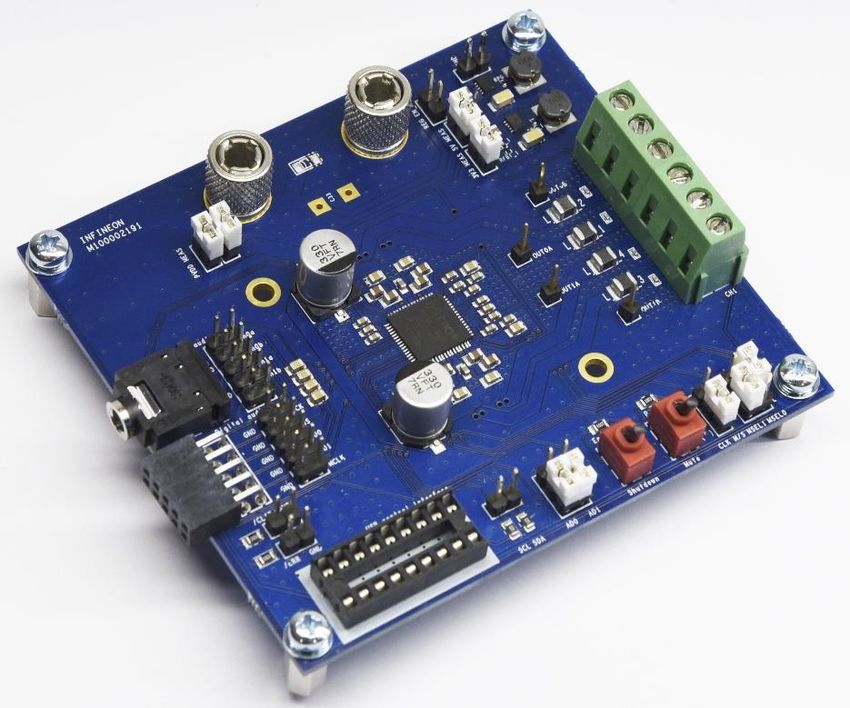
Product overview and features
Overview
The demonstration board EVAL_AUDIO_MA12040 is an evaluation and demonstration
board for MERUS™ audio MA12040. It contains analog inputs and a variety of output
and setup/selection features. It also contains two on-board power supply generators (5 V
and 3.3 V buck-converted) so only one external power supply (PVDD) is necessary. The
board can be used for evaluating or demonstrating key features/advantages of the
MERUS™ technology:
>     Energy efficiency: Power losses at typical audio listening levels / Idle power loss
>     Adaptive power management system
>     Minimum output filter components: Significant cost and size reduction.
>     THD performance and audio quality

›     General features and audio performance
Number of audio channels                            2xBTL, 1xPBTL, 1xBTL+2xSE
Audio input format                                  Analog
Amplifier gain                                      20 dB / configurable 26dB
Supply voltage                                      18 V
Output noise level                                  100 dB
Idle consumption @ PVDD=18V

Board description
                                                             3V3 / 5 V internal supply with
                                                             measurement and enable
                                                             jumpers                                                >      Recommended operation conditions
                               Power supply terminals
                                                                                                                           Parameter             Part Nr         Minimum          Nominal   Maximum        Unit

                                                                                                                             PVDD               MA12040             5.5                       18            V

Power input                                                                                                            Output peak current      MA12040                                       6.0           A
measurement
jumpers
                                                                                                                      AC Analog input level
                                                                                                                                                MA12040                                       6.0          Vpk
                                                                                                                     IN0A, IN0B, IN1A, IN1B

Analog                                                                                    0B
audio input                                                                               GND
                                                                                                                    >
(non p versions)                                                                                 Speaker
                                                                                          0A                               Typical audio and electrical specifications
                                                                                                  output                    (BTL default configuration; Power Mode Profile = 0)
I2S digital                                                                               1A    terminals
audio input                                                                                                                     Parameter                            Conditions                 Typ        Unit
                                                                                          GND
(p versions only)
                                                                                          1B                          Output power p/channel (peak)      THD+N = 10%, RL = 4 Ω, f = 1 kHz        40         W

                                                                                                                      Output power p/channel (peak)      THD+N = 10%, RL = 8 Ω, f = 1 kHz        20         W
 Error and clipping
 reading outputs                                                                                                     Total harmonic distortion + noise   1kHz, POUT = 1 W, RL = 4 Ω            0.008        %

                                                                                                                     Total harmonic distortion + noise   1kHz, POUT = 20 W, RL = 4 Ω           0.010        %

                                                                                                                                Efficiency*              POUT = 2×40 W, 4 Ω , PMP = 0            87         %

                                    I2C      I2C         Device           Output                                                Efficiency*              POUT = 2×20 W, 8 Ω , PMP = 0            91         %
                      USB control   serial   address     enable/          configuration
                       interface    clock    selection   mute             jumpers
                                    and data
                        Figure 2. Top board view of EVAL_AUDIO_MA12040
                                                                                                                     * Efficiency values do not take into account the 5 V and 3V3 board power supplies’ consumption.

   2019-04-25                                                      Copyright © Infineon Technologies AG 2019. All rights reserved.                                                                     3
Default configuration for a quick start
  Slides 4 and 5 describe the start up and quick start                                                        Verify that the jumpers are set in the following positions:
  operation procedures with the following configuration:
                                                                                                                                     Jumper                 State                  Picture

      Single ended audio sources                                                                                                 MSEL0                         H

                                                                                                                                 MSEL1                         L

                                                                                                                                 CLK M/S                     H(M)

                                                                                                                                 AD0 & AD1                     L

                                                                                                                                                    Jack input = all jumpered
                                                                                                                                 Analog audio    Balanced input = use individual
                                                                                                                                                             pints.

                                                                                                                                 Digital audio        Do not Jumper

                                                        Bridge tied load (BTL)
                                                               outputs                                                           PVDD MEAS               Jumpered
      Figure 3. Bridge tied load (BTL) configuration with single ended inputs for MA12040
                                                                                                                                 3V3 & 5V
                                                                                                                                                         Jumpered
                                                                                                                                 MEAS

                                                                                                                                 REG EN_N             Do not Jumper
Note: Please refer to the manual for other Input/Output configurations. Typically
balanced/differential inputs should be used to obtain optimum audio performance.

   2019-04-25                                                             Copyright © Infineon Technologies AG 2019. All rights reserved.                                                    4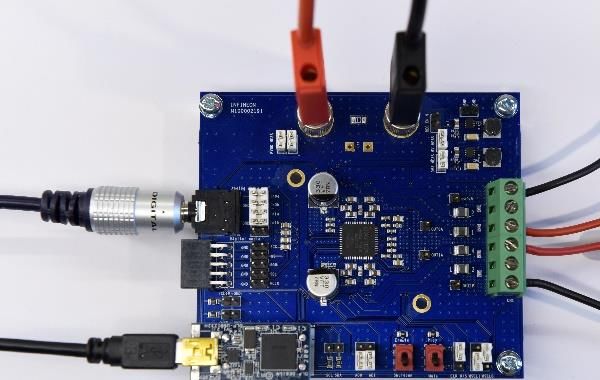
Power up and start procedure
Although it is not necessary to configure the MA12040 for quick start                                             4.    Make sure toggle buttons are in “shutdown” and “mute”
purposes, the following slides describe also the installation process of                                                positions.
its software tool. This will allow to monitor and configure the power
mode profiles. Power mode profile 0 is configured by default.

1.   Before connecting any source or load (speaker) make sure all of them
     are turned off.                                                                                                                Figure 6. Toggle buttons set to “mute” and “shutdown”

2.    Open your web browser and download the USB control interface drivers                                         5.     Connect all the sources and speaker/load cables:
     from the following Link. Press “setup executable” to download the                                                    a) Audio source to the analog audio jack input
     automatic installation. Run the downloaded file “CDM21228_Setup” and                                                 b) Power source and its ground to PVDD and GND
     follow the instructions to install the driver. Do not connect the USB cable                                          c) Speaker/load to audio output terminals
     while the installing process in running.                                                                             d) USB control interface to the computer.

                                                Figure 4. File download for USB control interface drivers

3.    Open your web browser and download the software from the following
     Link. A complete folder will be downloaded with the executable file
     “MA120xx_GUI” of gui software.

                                                    Figure 5. File download for GUI software                                        Figure 7. Complete evaluation board connections.

2019-04-25                                                        Copyright © Infineon Technologies AG 2019. All rights reserved.                                                       5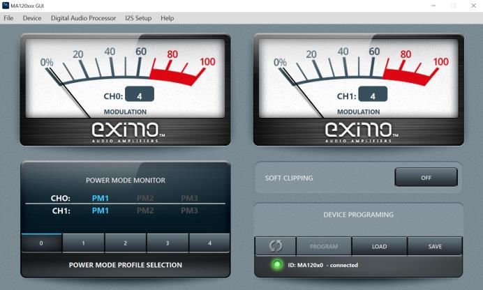
Power up and start procedure
6. Turn on the PVDD supply                                                                             9. If the connection was successful it will be indicated in the ID
                                                                                                          status line:
7. Start board by setting toggle switch to “enable” position.

                                                                                                                                    Figure 10. Control interface indicating a
                                                                                                                                    successful communication with the board.

                                                                                                       10. Start playing music from your audio source and set the toggle
                Figure 8. Left toggle switch set to “enable” position.
                                                                                                           switch to “play” position. You will be able to monitor the
8. Open the “MA120xx_GUI” file to run the monitoring interface.                                            modulation index of both channels and the their current
                                                                                                           power modes. Also, the power mode profiles can be
                                                                                                           selected. For more information on power mode profiles
                                                                                                           please refer to the MA12040 data sheet and Infineon
                                                                                                           MERUS™ evaluation board user’s guide.

                                                                                                                                      Figure 11. Right toggle switch set to “play” position.

                   Figure 9. MA120xx control software interface

2019-04-25                                                        Copyright © Infineon Technologies AG 2019. All rights reserved.                                                              6
Audio measurements set up

The need for an external filter:
MA120xx and MA120xxP are filterless amplifiers enabled by
it’s MERUS™ audio multilevel technique. However, in order
to obtain reliable measurements results an external low-pass
filter is required in front of the input stage. This is because
fast transients in the switching output signal might stress the
bandlimited input of measurement instruments. Therefore,
slew rate limiting and other distortion artifacts may appear
due to this stress if no external filtering is applied.

                                                                                                       Figure 12. Measurement setup for MA120xx amplifiers.

2019-04-25                                        Copyright © Infineon Technologies AG 2019. All rights reserved.                                             7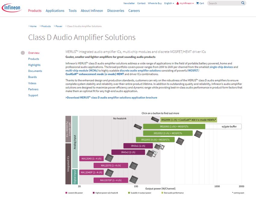
Support
www.infineon.com/merus
                                  › Product briefs
                                  › Selection guides
              Collaterals and     › Application brochures
                brochures         › Presentations
                                  › Articles

                                  › Application notes
                                  › Whitepapers
             Technical material   › Datasheets, MCDS files
                                  › PCB design data

                                  › Evaluation boards
             Evaluation boards    › Demoboards
                                  › Reference designs

                                  › Technical videos
                  Videos          › Product information videos
                                  › Tradeshow videos

2019-04-25                                              Copyright © Infineon Technologies AG 2019. All rights reserved.   8
Support
Online tools and services
3 4 5
2
1
Get support
2
Tools, finders
and selectors
3
Subscribe to
newsletter
4
1
Where to buy
5
myInfineon
2019-04-25 Copyright © Infineon Technologies AG 2019. All rights reserved. 9Tailor made information via myInfineon
A confirmation email
From the infineon.com Use the form to self- with the activation link is
go to the registration register (type in sent to you, please click Log in to myInfineon
page necessary information) on the link to activate
your account
In case of problems with the access, the registration or all other type of issues, please get in
touch with your Infineon contact person or with our official support at
www.infineon.com/support (available 24/7)
2019-04-25 Copyright © Infineon Technologies AG 2019. All rights reserved. 10You can also read